EP2079083A2 - Dispositif à rayons X compact et léger - Google Patents
Dispositif à rayons X compact et léger Download PDFInfo
- Publication number
- EP2079083A2 EP2079083A2 EP09000038A EP09000038A EP2079083A2 EP 2079083 A2 EP2079083 A2 EP 2079083A2 EP 09000038 A EP09000038 A EP 09000038A EP 09000038 A EP09000038 A EP 09000038A EP 2079083 A2 EP2079083 A2 EP 2079083A2
- Authority
- EP
- European Patent Office
- Prior art keywords
- ray
- irradiation region
- shutter
- unit
- ray irradiation
- Prior art date
- Legal status (The legal status is an assumption and is not a legal conclusion. Google has not performed a legal analysis and makes no representation as to the accuracy of the status listed.)
- Granted
Links
Images


Classifications
-
- A—HUMAN NECESSITIES
- A61—MEDICAL OR VETERINARY SCIENCE; HYGIENE
- A61B—DIAGNOSIS; SURGERY; IDENTIFICATION
- A61B6/00—Apparatus or devices for radiation diagnosis; Apparatus or devices for radiation diagnosis combined with radiation therapy equipment
-
- G—PHYSICS
- G21—NUCLEAR PHYSICS; NUCLEAR ENGINEERING
- G21K—HANDLING OF PARTICLES OR IONISING RADIATION NOT OTHERWISE PROVIDED FOR; IRRADIATION DEVICES; GAMMA RAY OR X-RAY MICROSCOPES
- G21K1/00—Arrangements for handling particles or ionising radiation, e.g. focusing or moderating
- G21K1/02—Arrangements for handling particles or ionising radiation, e.g. focusing or moderating using diaphragms, collimators
- G21K1/04—Arrangements for handling particles or ionising radiation, e.g. focusing or moderating using diaphragms, collimators using variable diaphragms, shutters, choppers
-
- A—HUMAN NECESSITIES
- A61—MEDICAL OR VETERINARY SCIENCE; HYGIENE
- A61B—DIAGNOSIS; SURGERY; IDENTIFICATION
- A61B6/00—Apparatus or devices for radiation diagnosis; Apparatus or devices for radiation diagnosis combined with radiation therapy equipment
- A61B6/06—Diaphragms
-
- A—HUMAN NECESSITIES
- A61—MEDICAL OR VETERINARY SCIENCE; HYGIENE
- A61B—DIAGNOSIS; SURGERY; IDENTIFICATION
- A61B6/00—Apparatus or devices for radiation diagnosis; Apparatus or devices for radiation diagnosis combined with radiation therapy equipment
- A61B6/08—Auxiliary means for directing the radiation beam to a particular spot, e.g. using light beams
-
- A—HUMAN NECESSITIES
- A61—MEDICAL OR VETERINARY SCIENCE; HYGIENE
- A61B—DIAGNOSIS; SURGERY; IDENTIFICATION
- A61B6/00—Apparatus or devices for radiation diagnosis; Apparatus or devices for radiation diagnosis combined with radiation therapy equipment
- A61B6/44—Constructional features of apparatus for radiation diagnosis
- A61B6/4405—Constructional features of apparatus for radiation diagnosis the apparatus being movable or portable, e.g. handheld or mounted on a trolley
-
- A—HUMAN NECESSITIES
- A61—MEDICAL OR VETERINARY SCIENCE; HYGIENE
- A61B—DIAGNOSIS; SURGERY; IDENTIFICATION
- A61B6/00—Apparatus or devices for radiation diagnosis; Apparatus or devices for radiation diagnosis combined with radiation therapy equipment
- A61B6/58—Testing, adjusting or calibrating thereof
- A61B6/587—Alignment of source unit to detector unit
-
- A—HUMAN NECESSITIES
- A61—MEDICAL OR VETERINARY SCIENCE; HYGIENE
- A61B—DIAGNOSIS; SURGERY; IDENTIFICATION
- A61B6/00—Apparatus or devices for radiation diagnosis; Apparatus or devices for radiation diagnosis combined with radiation therapy equipment
- A61B6/58—Testing, adjusting or calibrating thereof
- A61B6/588—Setting distance between source unit and detector unit
Definitions
- the present invention relates to an X-ray device and, more particularly, to an X-ray device smaller in size and weight than conventional ones, in which device an X-ray irradiation region is visually indicated by laser light without having to use a lamp otherwise provided between an X-ray tube that irradiates a beam of X-rays on an object and a shutter that regulates the irradiation area of the beam of X-rays irradiated on the object.
- An X-ray device refers to, e.g., a device that diagnoses the health condition of a human patient or an animal by transmitting a beam of X-rays through an object such as the human patient or the animal and acquiring an X-ray image from the beam of X-rays coming out of the object.
- FIG. 1 Shown in Fig. 1 is a conventional portable X-ray device.
- an X-ray device 10 is designed to generate a beam of X-rays and irradiate it on an image capturing unit 20.
- the image capturing unit 20 use is made of a digital imaging panel that can capture an X-ray image using an X-ray film or a multiplicity of photo sensors.
- An object 30 whose X-ray image is to be captured is positioned between the X-ray device 10 and the image capturing unit 20.
- the beam of X-rays irradiated from the X-ray device 10 pass through the object 30.
- the image capturing unit 20 captures an X-ray image of the object 30.
- the unit that enables a user to visually identify and adjust the X-ray irradiation region is typically referred to as a collimator.
- the collimator serves to direct the light of a lamp toward the X-ray irradiation region, thereby enabling the user to identify the X-ray irradiation region through the lamp light.
- Fig. 2 shows an exemplary use of the conventional X-ray device 10 that indicates an X-ray irradiation region with a typical lamp.
- a collimator for indicating an X-ray irradiation region with a lamp is provided within the X-ray device 10.
- the collimator illuminates the light of a lamp on an image capturing unit 20.
- the light thus illuminated divides the image capturing unit 20 into an illumination region 35 and a non-illumination region 37.
- the illumination region 35 of the image capturing unit 20 is equivalent to an actual X-ray irradiation region. Based on the illumination region 35, the user can identify the actual X-ray irradiation region and can accurately take an X-ray image of a target portion of an object by positioning the target portion in the illumination region 35.
- Fig. 3 schematically depicts the internal construction of the conventional X-ray device in which an X-ray irradiation region is indicated with a typical lamp.
- a reflection mirror 15 having a specified inclination relative to an X-ray irradiation axis 12 is arranged between an X-ray tube 11 that generates and irradiates a beam of X-rays on an object and a shutter 17 and 18 that regulates the irradiation area of the beam of X-rays.
- a lamp 13 is arranged below the reflection mirror 15 so that the light emitted from the lamp 13 can be illuminated on the reflection mirror 15.
- the illumination area of the light moving along the X-ray irradiation axis 12 is regulated by the shutter 17 and 18, after which the light is illuminated on an image capturing unit.
- the illumination area of the light on the image capturing unit is the same as the X-ray irradiation region over which the beam of X-rays are actually irradiated by the x-ray tube 11. The user can identify the X-ray irradiation region by observing the illumination region of the light illuminated on the image capturing unit.
- Fig. 3 shows only an upper shutter blade 17 for regulating an upper edge of the beam of X-rays irradiated on the object and a lower shutter blade 18 for regulating a lower edge of the beam of X-rays. It should be noted, however, that the X-ray device further includes a left shutter blade for regulating a left edge of the beam of X-rays and a right shutter blade for regulating a right edge of the beam of X-rays.
- the lamp has to be arranged between the X-ray tube and the shutter in order for the user to identify the X-ray irradiation region.
- This makes it necessary to provide a lamp-receiving space between the X-ray tube and the shutter. It is also necessary to provide a space and a vent hole for dissipating the heat generated from the lamp.
- the conventional X-ray device is doomed to be fabricated with a greater size and an increased weight.
- the conventional X-ray device has a problem in that a large amount of electric power is consumed in operating the lamp.
- the size of the shutter required to regulate the irradiation area of the beam of X-rays becomes greater as the shutter is positioned farther away from the focal point of the X-ray tube.
- the shutter is made of heavy and X-ray impermeable lead that can effectively regulate the irradiation area of the beam of X-rays irradiated on the object.
- the size and weight of the X-ray device is increased in proportion to the size of the shutter.
- the distance between the X-ray tube and the focal point must be greater than a specified value to accommodate the lamp and the reflection mirror. This poses a problem in that the conventional X-ray device is constrained to use a shutter having a greater size and an increased weight.
- Another object of the present invention is to provide a compact and lightweight X-ray device that eliminates the need to use a lamp and a reflection mirror.
- a collimator for use in an X-ray device comprising: a shutter arranged around an X-ray irradiation axis for regulating an X-ray irradiation region; a laser pointer generating unit for generating a laser pointer used to indicate the X-ray irradiation region regulated by the shutter; and a reflection mirror arranged on the X-ray irradiation axis in an inclined relationship therewith for reflecting the laser pointer toward the X-ray irradiation region.
- an X-ray device comprising: an X-ray generation unit for generating a beam of X-rays; a collimator for regulating an X-ray irradiation region on which the beam of X-rays is irradiated, the collimator being designed to indicate the X-ray irradiation region with a laser pointer; and a power source for supplying an electric current to the X-ray generation unit and the collimator.
- an X-ray device for irradiating a beam of X-rays on an object to capture an X-ray image of the object, comprising: an X-ray tube for generating the beam of X-rays and irradiating the beam of X-rays on the object; a shutter arranged around an X-ray irradiation axis for regulating an X-ray irradiation region on which the beam of X-rays is irradiated through the object; and a visual indicator unit arranged on the shutter for movement together with the shutter, the visual indicator unit being designed to visually indicate the X-ray irradiation region.
- an X-ray device for irradiating a beam of X-rays on an object to capture an X-ray image of the object, comprising: an X-ray tube for generating the beam of X-rays and irradiating the beam of X-rays on the object; an irradiation region setting unit for presetting the size of an X-ray irradiation region on which the beam of X-rays is irradiated through the object; a shutter arranged around an X-ray irradiation axis for regulating the X-ray irradiation region depending on the size preset by the irradiation region setting unit; and a visual indicator unit arranged on the shutter for visually indicating the X-ray irradiation region.
- an X-ray device for irradiating a beam of X-rays on an object to capture an X-ray image of the object, comprising: an X-ray tube for generating the beam of X-rays and irradiating the beam of X-rays on the object; an irradiation region setting unit for presetting the size of an X-ray irradiation region on which the beam of X-rays is irradiated through the object; a shutter arranged around an X-ray irradiation axis for regulating the X-ray irradiation region depending on the size preset by the irradiation region setting unit; a visual indicator unit arranged independently of the shutter for visually indicating the X-ray irradiation region, the visual indicator unit being movable in synchronism with movement of the shutter; and a drive unit associated with the irradiation region setting unit for driving the visual indicator unit in
- a laser is used in place of a lamp. This makes it possible to reduce heat generation and power consumption in the X-ray device while enabling a user to readily identify an X-ray irradiation region.
- a display unit that enables a user to identify an X-ray irradiation region is arranged in a shutter. Therefore, there is no need to arrange a lamp and a reflection mirror between the X-ray tube and the shutter. This makes it possible to fabricate an X-ray device with a small size and a reduced weight. It is also possible to shorten the distance between the focal point of the X-ray tube and the shutter, which makes it possible reduce the size of the shutter that regulates the irradiation area of the beam of X-rays irradiated on an object.
- Fig. 4 is a functional block diagram showing a portable X-ray device provided with a collimator.
- a user command for preliminarily identifying an X-ray irradiation region is inputted though a user interface 21 prior to taking an X-ray image of an object.
- a control unit 23 causes a battery 25 to supply an electric current to a collimator 27.
- the collimator 27 uses the electric current, the collimator 27 generates a laser pointer with a specific pattern and directs the laser pointer toward an image capturing unit 20 (see Figs. 6 and 7 ).
- the laser pointer appearing on the image capturing unit 20 enables the user to identify an X-ray irradiation region prior to taking an image of the object.
- a target portion of the object is positioned in the X-ray irradiation region identified through the laser pointer. Then, a user command for taking the image of the object is inputted through the user interface 21. In response to the user command thus inputted, the control unit 23 causes the battery 25 to supply an electric current to an X-ray generation unit 11. Using the electric current, the X-ray generation unit 11 generates a beam of X-rays and irradiates it toward the image capturing unit 20 so that the image capturing unit 20 can take an X-ray image of the object.
- Fig. 5 schematically illustrates the internal construction of an X-ray device with a laser pointer collimator in accordance with a first embodiment of the present invention.
- the X-ray device includes a laser light generator unit 31 which is supplied with an electric current to generate laser light.
- the laser light generator 31 examples include: a solid-state laser in which the crystals of artificial ruby, glass or YAG (yttrium aluminum garnet) containing chromium ions are used as a laser light generating material; a gas-state laser in which a mixture gas of helium and neon, argon, krypton, carbon dioxide or a mixture gas of helium and nitrogen is used as a laser light generating material; and a semiconductor laser in which laser light is generated by allowing an electric current to flow through a p-n junction diode consisting of p-type and n-type gallium arsenide semiconductors.
- the laser light generator 31 is supplied with an electric current from the battery 25.
- the X-ray device includes a patterning lens 32 having a plurality of through-holes formed in a specified pattern.
- the laser light generated in the laser light generator 31 is transmitted through the through-holes so that the laser light corresponding to the pattern of the through-holes can be irradiated on a reflection mirror 15.
- the reflection mirror 15 is positioned on an X-ray irradiation axis 12 in an inclined relationship with respect thereto and serves to reflect the laser light coming from the patterning lens 32 in the same direction as the X-ray irradiation axis 12.
- the X-ray device includes a shutter for regulating an X-ray irradiation region.
- the shutter includes shutter blades 17 and 18 symmetrically arranged above and below the X-ray irradiation axis 12.
- shutter blades for regulating the length of the X-ray irradiation region and shutter blades for regulating the width of the X-ray irradiation region are symmetrically arranged at the upper, lower, left and right sides of the X-ray irradiation axis 12.
- Fig. 5 only the shutter blades 17 and 18 arranged at the upper and lower sides of the X-ray irradiation axis 12 are shown in Fig. 5 .
- the X-ray irradiation region is changed by increasing or decreasing the gap size between the shutter blades 17 and 18.
- the illumination area of the laser light reflected from the reflection mirror 15 is regulated by the shutter blades 17 and 18.
- the illumination area of the laser light is substantially the same as the X-ray irradiation region.
- Fig. 6 schematically illustrates the internal construction of an X-ray device in accordance with a second embodiment of the present invention.
- the beam of X-rays generated in an X-ray tube 11 is irradiated on the image capturing unit 20.
- a shutter for regulating the X-ray irradiation region is arranged in front of the X-ray tube 11 along the X-ray irradiation direction. It is preferred that the distance d between the focal point of the X-ray tube 11 and the shutter is as small as possible.
- the shutter includes an upper shutter blade 110 for regulating the upper edge of the X-ray irradiation region and a lower shutter blade 111 for regulating the lower edge of the X-ray irradiation region.
- an upper shutter blade 110 for regulating the upper edge of the X-ray irradiation region
- a lower shutter blade 111 for regulating the lower edge of the X-ray irradiation region.
- the shutter further includes left and right shutter blades for regulating the left and right edges of the X-ray irradiation region.
- the beam of X-rays emitted from the X-ray tube 11 is irradiated on the image capturing unit 20 through the shutter, at which time the X-ray irradiation region on the image capturing unit 20 are regulated by the upper, lower, left and right shutter blades.
- Laser irradiation units 120 and 121 which constitute a visual indicator unit defined in the claims, are attached to the rear surfaces (the outer sides) of the upper shutter blade 110 and the lower shutter blade 111 opposite from the X-ray tube 11.
- the laser irradiation unit 120 attached to the upper shutter blade 110 emits laser light along the upper edge of the beam of X-rays irradiated on the image capturing unit 20 through the shutter.
- the laser irradiation unit 121 attached to the lower shutter blade 111 emits laser light along the lower edge of the beam of X-rays irradiated on the image capturing unit 20 through the shutter.
- the laser light emitted from the laser irradiation units 120 and 121 indicates the upper and lower edges of the X-ray irradiation region on the image capturing unit 20.
- laser irradiation units are attached to the rear surfaces (the outer sides) of the left shutter blade and the right shutter blade opposite from the X-ray tube 11.
- the laser irradiation unit attached to the left shutter blade emits laser light along the upper edge of the beam of X-rays irradiated on the image capturing unit 20 through the shutter.
- the laser irradiation unit attached to the right shutter blade emits laser light along the right edge of the beam of X-rays irradiated on the image capturing unit 20 through the shutter.
- the laser light emitted from the laser irradiation units attached to the left and right shutter blades indicates the left and right edges of the X-ray irradiation region on the image capturing unit 20.
- Fig. 7 schematically shows a modified example of the X-ray device in accordance with the second embodiment of the present invention.
- the X-ray device shown in Fig. 7 is essentially the same as the X-ray device illustrated in Fig. 6 , except that the laser irradiation units 120 and 121 are attached to the front surfaces (the inner sides) of the upper shutter blade 110 and the lower shutter blade 111 that face toward the X-ray tube 11. This holds true in case of the laser irradiation units attached to the left shutter blade and the right shutter blade.
- Figs. 8 , 9A and 9B are views for specifically explaining the shutter employed in the present invention.
- a first shutter includes an upper shutter blade 110 and a lower shutter blade 111, both of which serve to shift the X-ray irradiation region in the vertical direction.
- a second shutter includes a left shutter blade 113 and a right shutter blade 114, both of which serve to shift the X-ray irradiation region in the lateral direction.
- the first and second shutters are moved vertically and laterally in an overlapped state to form an aperture S of varying size that defines the X-ray irradiation region.
- Fig. 9A is a side view of the shutters
- the upper shutter blade 110 and the lower shutter blade 111 of the first shutter are curved to have a first radius r1 from the focal point of the beam of X-rays.
- the upper shutter blade 110 and the lower shutter blade 111 are movable upwards or downwards along the arc of a circle with the first radius r1.
- the laser irradiation units 120 and 121 are attached to the lower end of the upper shutter blade 110 and the upper end of the lower shutter blade 111, respectively.
- the laser irradiation units 120 and 121 are also moved along the same trajectory as that of the upper shutter blade 110 and the lower shutter blade 111.
- the laser irradiation unit 120 attached to the upper shutter blade 110 emits laser light in the direction A along the upper edge of the beam of X-rays to indicate the upper edge of the X-ray irradiation region on the image capturing unit 20.
- the laser irradiation unit 121 attached to the upper shutter blade 111 emits laser light in the direction B along the lower edge of the beam of X-rays to indicate the lower edge of the X-ray irradiation region on the image capturing unit 20.
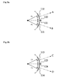
- Fig. 9B is a top plan view of the shutters
- the left shutter blade 113 and the right shutter blade 114 of the second shutter are curved to have a second radius r2 from the focal point of the beam of X-rays.
- the left shutter blade 113 and the right shutter blade 114 are movable to the left or the right along the arc of a circle with the second radius r2.
- Laser irradiation units 123 and 124 are attached to the right end of the left shutter blade 113 and the left end of the right shutter blade 114, respectively.
- the laser irradiation units 123 and 124 are also moved along the same trajectory as that of the left shutter blade 113 and the right shutter blade 114.
- the laser irradiation unit 123 attached to the left shutter blade 113 emits laser light in the direction C along the left edge of the beam of X-rays to indicate the left edge of the X-ray irradiation region on the image capturing unit 20.
- the laser irradiation unit 124 attached to the right shutter blade 114 emits laser light in the direction D along the right edge of the beam of X-rays to indicate the right edge of the X-ray irradiation region on the image capturing unit 20.
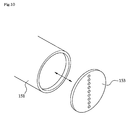
- the laser irradiation unit includes a laser light generator 151 for generating laser light and a patterning lens 153 for changing the laser light into a specified pattern before it is irradiated on the image capturing unit.
- the laser light generator 151 may be a solid-state laser, a gas-state laser or a semiconductor laser, the classification of which depends on the material used and the mode of operation.
- the patterning lens 153 has a plurality of through-holes arranged in a predetermined pattern and designed to create a laser identification mark that indicates the upper, lower, left or right edges of the X-ray irradiation region.
- the laser light generated in the laser light generator 151 is split into an array of light beams of a predetermined pattern while passing through the through-holes of the patterning lens 153. Then the array of light beams is irradiated on the image capturing unit and is used as the laser identification mark that indicates the X-ray irradiation region.
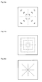
- Figs. 11A and 11B illustrate different examples of the laser identification mark formed on the image capturing unit 20 by the array of light beams passing through the through-holes of the patterning lens 153.
- laser light is employed to indicate the X-ray irradiation region in the foregoing embodiments, it may also be possible to use other coherent light depending on the application of the present invention. This also falls within the scope of the present invention.
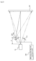
- Fig. 12 schematically shows the internal construction of an X-ray device in accordance with a third embodiment of the present invention.
- the beam of X-rays generated in the X-ray tube 11 is irradiated on the image capturing unit 20.
- a shutter for regulating the X-ray irradiation region is arranged in front of the X-ray tube 11 along the X-ray irradiation direction. It is preferred that the distance d between the focal point of the X-ray tube 11 and the shutter is as small as possible.
- the shutter includes an upper shutter blade 210 for regulating the upper edge of the X-ray irradiation region and a lower shutter blade 211 for regulating the lower edge of the X-ray irradiation region.
- an upper shutter blade 210 for regulating the upper edge of the X-ray irradiation region
- a lower shutter blade 211 for regulating the lower edge of the X-ray irradiation region.
- the upper and lower shutter blades 210 and 211 and the left and right shutter blades are moved vertically and laterally depending on the size of the X-ray irradiation region preset by an irradiation region setting unit 230.
- the irradiation region setting unit 230 includes a setting part for presetting the size of the X-ray irradiation region and a drive part for driving the shutter depending on the size of the X-ray irradiation region preset by the setting part.
- the drive part includes a plurality of gears operatively connected to the shutter and an electric motor for rotating the gears.
- the drive part displaces the upper and lower shutter blades 210 and 211 and the left and right shutter blades to form an aperture corresponding to the X-ray irradiation region on the image capturing unit 20.
- Figs. 13A and 13B illustrate different examples of the setting part of the irradiation region setting unit 230.
- a rotary knob is mounted to a housing of the X-ray device.
- a reference mark that indicates the current size of the X-ray irradiation region is placed on the top surface of the rotary knob.
- a plurality of graduations "1", “2” and “3" that indicates the varying size of the X-ray irradiation region is placed on the housing 61 of the X-ray device.
- the size of the X-ray irradiation region can be arbitrarily set by turning the rotary knob so that the reference mark on the rotary knob can be aligned with one of the graduations "1", “2” and "3".
- the setting part includes a display and a keypad arranged on the surface of the housing of the X-ray device.
- the key pad includes a plurality of size selection keys "1", “2" and “3" that can be pressed to select the size of the X-ray irradiation region and an input key that can be pressed to input the size of the X-ray irradiation region selected. If a user presses, e.g., the size selection key "2", the length and width of the X-ray irradiation region is displayed on the display to read, e.g., "SIZE 2, 45 cm x 45 cm”. Then the user presses the input key to finalize the task of selecting the size of the X-ray irradiation region.
- a laser irradiation unit 220 is arranged on the opposite side of the upper shutter blade 210 from the X-ray tube 11.
- the laser irradiation unit 220 irradiates laser light toward the image capturing unit 20 to indicate the X-ray irradiation region whose size has been selected by the irradiation region setting unit 230.
- Figs. 14A, 14B and 14C illustrate different examples of the laser identification mark appearing on the image capturing unit.
- the size of the X-ray irradiation region preset through the use of the irradiation region setting unit 230 is indicated on the image capturing unit 20 by irradiating the laser light to form a laser identification mark having an angle bracket shape or a square shape.
- the size of the X-ray irradiation region preset through the use of the irradiation region setting unit 230 is indicated on the image capturing unit 20 by irradiating the laser light to form a laser identification mark having a dot axis shape.
- the laser irradiation unit 220 is arranged in a position nearest to the shutter insofar as it does not interrupt the beam of X-rays irradiated toward the image capturing unit 20 through the shutter.
- the laser irradiation unit 220 is fixedly arranged on the opposite surface of the shutter from the X-ray tube 11 so that the deviation between the actual X-ray irradiation region actually irradiated by the beam of X-rays and the target X-ray irradiation region indicated by the laser identification mark is equal to or smaller than a first threshold value.
- the shutter blades are moved to ensure that the beam of X-rays is irradiated on the preset X-ray irradiation region.
- the user can determine the actual X-ray irradiation region by observing the laser identification mark mapped to the size of the preset X-ray irradiation region.
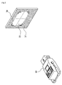
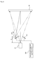
- Fig. 15 schematically shows a modified example of the X-ray device in accordance with the third embodiment of the present invention, in which a camera unit 321 is used in place of the laser irradiation unit 220.
- the beam of X-rays generated in the X-ray tube 11 is irradiated toward the image capturing unit 20.
- a shutter for regulating the X-ray irradiation region is arranged in front of the X-ray tube 11 along the X-ray irradiation direction. It is preferred that the distance d between the focal point of the X-ray tube 11 and the shutter is as small as possible.
- the shutter includes an upper shutter blade 310 for regulating the upper edge of the X-ray irradiation region and a lower shutter blade 311 for regulating the lower edge of the X-ray irradiation region.
- an upper shutter blade 310 for regulating the upper edge of the X-ray irradiation region
- a lower shutter blade 311 for regulating the lower edge of the X-ray irradiation region.
- the upper and lower shutter blades 310 and 311 and the left and right shutter blades are moved vertically and laterally depending on the size of the X-ray irradiation region preset by an irradiation region setting unit 330.
- the irradiation region setting unit 330 includes a setting part for presetting the size of the X-ray irradiation region and a drive part for driving the shutter depending on the size of the X-ray irradiation region preset by the setting part.
- the drive part includes a plurality of gears operatively connected to the shutter and an electric motor for rotating the gears.
- the drive part displaces the upper and lower shutter blades 210 and 211 and the left and right shutter blades to form an aperture corresponding to the X-ray irradiation region on the image capturing unit 20.
- a camera unit 321 is arranged on the opposite surface of the shutter from the X-ray tube 11.
- the camera unit 321 is designed to take an image of the X-ray irradiation region on the image capturing unit 20.
- the camera unit 321 is arranged in a position nearest to the shutter insofar as it does not interrupt the beam of X-rays irradiated toward the image capturing unit 20 through the shutter.
- the camera unit 321 is fixedly arranged on the opposite surface of the shutter from the X-ray tube 11 so that the deviation between the actual X-ray irradiation region actually irradiated by the beam of X-rays and the target X-ray irradiation region taken by the camera unit 321 is equal to or smaller than a first threshold value.
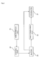
- Fig. 16 is a functional block diagram showing a visual indicator module employed in the X-ray device shown in Fig. 15 .
- the visual indicator that forms a part of the X-ray device includes a camera unit 321 for taking an image of the X-ray irradiation region, a display unit 325 for displaying an actual X-ray irradiation region and a control unit 323 responsive to a user command inputted through a setting unit for controlling the display unit 325 to display the actual X-ray irradiation region extracted from the image of the X-ray irradiation region.
- the control unit 323 is supplied with the image of the X-ray irradiation region taken by the camera unit 321. Responsive to the user command inputted through the setting unit, the control unit 323 identifies the actual X-ray irradiation region contained in the image of the X-ray irradiation region. Then the control unit 323 controls the display unit 325 to display the actual X-ray irradiation region with or without an identification mark.
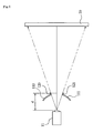
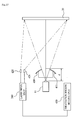
- Fig. 17 schematically shows the internal construction of an X-ray device in accordance with a fourth embodiment of the present invention, which is provided with an independently arranged laser irradiation unit.
- the X-ray device includes laser irradiation units 420 and 421 arranged independently of the shutter.
- the X-ray device further includes an irradiation region setting unit 430 that displaces the upper and lower shutter blades 410 and 411 and the left and right shutter blades to form an aperture corresponding to the X-ray irradiation region preset by the user.
- the X-ray device further includes a laser drive unit 240 associated with the irradiation region setting unit 430.
- the laser drive unit 240 controls the laser irradiation units 420 and 421 in synchronism with the movement of the shutter.
- the laser irradiation units 420 and 421 are controlled by the laser drive unit 240 to irradiate a beam of X-rays toward the image capturing unit 20 so that a laser identification mark indicating the X-ray irradiation region preset through the use of the irradiation region setting unit 430 can be displayed on the image capturing unit 20.
- the X-ray device of the foregoing embodiments may be operated through the use of a general computer having a computer-readable medium that stores a program needed to operate the X-ray device.
- the computer-readable medium include a magnetic storage medium (e.g., a ROM, a floppy disk and a hard disk), an optical recording medium (e.g., a CD ROM and a DVD) and a carrier wave (e.g., transmission through the Internet). While certain preferred embodiments of the present invention have been described hereinabove, the present invention is not limited thereto. It will be understood by those skilled in the art that various changes and modifications may be made without departing from the scope of the invention defined in the claims.
Landscapes
- Health & Medical Sciences (AREA)
- Life Sciences & Earth Sciences (AREA)
- Engineering & Computer Science (AREA)
- Medical Informatics (AREA)
- Physics & Mathematics (AREA)
- High Energy & Nuclear Physics (AREA)
- Radiology & Medical Imaging (AREA)
- Animal Behavior & Ethology (AREA)
- Optics & Photonics (AREA)
- Pathology (AREA)
- Biophysics (AREA)
- Biomedical Technology (AREA)
- Heart & Thoracic Surgery (AREA)
- Molecular Biology (AREA)
- Surgery (AREA)
- Nuclear Medicine, Radiotherapy & Molecular Imaging (AREA)
- General Health & Medical Sciences (AREA)
- Public Health (AREA)
- Veterinary Medicine (AREA)
- Spectroscopy & Molecular Physics (AREA)
- General Engineering & Computer Science (AREA)
- Apparatus For Radiation Diagnosis (AREA)
- X-Ray Techniques (AREA)
Applications Claiming Priority (1)
| Application Number | Priority Date | Filing Date | Title |
|---|---|---|---|
| KR1020080002070A KR100850500B1 (ko) | 2008-01-08 | 2008-01-08 | 작고 가볍게 제작 가능한 x선 촬영 장치 |
Publications (3)
| Publication Number | Publication Date |
|---|---|
| EP2079083A2 true EP2079083A2 (fr) | 2009-07-15 |
| EP2079083A3 EP2079083A3 (fr) | 2010-08-18 |
| EP2079083B1 EP2079083B1 (fr) | 2012-08-01 |
Family
ID=39881214
Family Applications (1)
| Application Number | Title | Priority Date | Filing Date |
|---|---|---|---|
| EP09000038A Active EP2079083B1 (fr) | 2008-01-08 | 2009-01-05 | Dispositif à rayons X compact et léger |
Country Status (4)
| Country | Link |
|---|---|
| US (1) | US8011829B2 (fr) |
| EP (1) | EP2079083B1 (fr) |
| KR (1) | KR100850500B1 (fr) |
| ES (1) | ES2392213T3 (fr) |
Cited By (1)
| Publication number | Priority date | Publication date | Assignee | Title |
|---|---|---|---|---|
| US9974504B2 (en) | 2011-07-18 | 2018-05-22 | Samsung Electronics Co., Ltd. | X-ray device and method for controlling X-ray irradiation area using the same |
Families Citing this family (9)
| Publication number | Priority date | Publication date | Assignee | Title |
|---|---|---|---|---|
| WO2011132359A1 (fr) * | 2010-04-20 | 2011-10-27 | 株式会社島津製作所 | Dispositif d'imagerie radiographique |
| KR101137156B1 (ko) * | 2010-05-14 | 2012-04-19 | 이레나 | 치과용 엑스선 영상 촬영장치용 엑스선 조사범위 표시장치 |
| KR101870905B1 (ko) * | 2011-07-18 | 2018-06-26 | 삼성전자주식회사 | 엑스선 장치 및 이를 이용한 엑스선 조사영역 조절방법 |
| KR101392637B1 (ko) * | 2012-09-13 | 2014-05-12 | 이성엽 | 씨암장치 |
| KR102377484B1 (ko) | 2015-04-20 | 2022-03-22 | 주식회사 바텍 | 모션 센서를 구비한 엑스선 조사 장치 및 이를 이용한 엑스선 촬영 방법 |
| JP2017108821A (ja) * | 2015-12-15 | 2017-06-22 | コニカミノルタ株式会社 | 放射線画像撮影システム |
| US10325691B2 (en) * | 2016-04-12 | 2019-06-18 | Consolidated Nuclear Security, LLC | X-ray beam alignment device and method |
| KR20180031895A (ko) * | 2016-09-20 | 2018-03-29 | 주식회사 포스콤 | 카메라를 구비하는 x선 촬영 장치 |
| KR102009085B1 (ko) * | 2017-10-25 | 2019-08-08 | 신한대학교 산학협력단 | 조사야 조절장치 |
Family Cites Families (14)
| Publication number | Priority date | Publication date | Assignee | Title |
|---|---|---|---|---|
| CH437627A (de) * | 1964-09-10 | 1967-06-15 | R Dr Johner Werner | Strahlenblende für durchdringende Strahlen |
| JPS58133239A (ja) * | 1982-02-02 | 1983-08-08 | 株式会社堀場製作所 | 照射x線領域モニタ−装置 |
| US4502147A (en) * | 1982-08-09 | 1985-02-26 | Charles Lescrenier | Means for visually indicating an X-ray field |
| US4603427A (en) * | 1983-12-16 | 1986-07-29 | Alpern Michael C | Collimator in a panoramic dental X-ray apparatus |
| DE68907924T2 (de) * | 1988-01-20 | 1993-11-11 | Horiba Ltd | Röntgenstrahlvorrichtung, ausgestattet mit einem Strahlungsbereich-Monitor. |
| DE4003757A1 (de) * | 1990-02-08 | 1991-08-14 | Roentgenanalytik Messtechnik G | Vorrichtung zum erzeugen und messen der von einer mit roentgenstrahlung bestrahlten probe ausgehenden sekundaerstrahlung |
| US5305363A (en) * | 1992-01-06 | 1994-04-19 | Picker International, Inc. | Computerized tomographic scanner having a toroidal x-ray tube with a stationary annular anode and a rotating cathode assembly |
| JPH0747063A (ja) * | 1993-08-05 | 1995-02-21 | Hitachi Medical Corp | X線照射野確認装置 |
| JPH11244282A (ja) * | 1998-02-27 | 1999-09-14 | Shimadzu Corp | X線可動絞り |
| JP4184839B2 (ja) * | 2003-03-13 | 2008-11-19 | 株式会社東芝 | 多分割絞り装置 |
| DE10319327A1 (de) * | 2003-04-29 | 2004-11-25 | Siemens Ag | Vorrichtung zur Strahlungsbildaufnahme |
| US6863439B2 (en) * | 2003-07-30 | 2005-03-08 | X-Cel X-Ray Corporation | Radiographic device having an adjustable head |
| US7281849B2 (en) * | 2004-07-21 | 2007-10-16 | General Electric Company | System and method for alignment of an object in a medical imaging device |
| DE102005056066B3 (de) * | 2005-11-24 | 2007-06-28 | Siemens Ag | Einrichtung für die Röntgen-Brachytherapie mit einer in das Innere eines Körpers einführbaren Sonde |
-
2008
- 2008-01-08 KR KR1020080002070A patent/KR100850500B1/ko active Active
-
2009
- 2009-01-05 ES ES09000038T patent/ES2392213T3/es active Active
- 2009-01-05 EP EP09000038A patent/EP2079083B1/fr active Active
- 2009-01-07 US US12/349,871 patent/US8011829B2/en active Active
Cited By (7)
| Publication number | Priority date | Publication date | Assignee | Title |
|---|---|---|---|---|
| US9974504B2 (en) | 2011-07-18 | 2018-05-22 | Samsung Electronics Co., Ltd. | X-ray device and method for controlling X-ray irradiation area using the same |
| US9974505B2 (en) | 2011-07-18 | 2018-05-22 | Samsung Electronics Co., Ltd. | X-ray device and method for controlling X-ray irradiation area using the same |
| US10092260B2 (en) | 2011-07-18 | 2018-10-09 | Samsung Electronics Co., Ltd. | X-ray device and method for controlling X-ray irradiation area using the same |
| US20180360401A1 (en) | 2011-07-18 | 2018-12-20 | Samsung Electronics Co., Ltd. | X-ray device and method for controlling x-ray irradiation area using the same |
| US10398396B2 (en) | 2011-07-18 | 2019-09-03 | Samsung Electronics Co., Ltd. | X-ray device and method for controlling X-ray irradiation area using the same |
| US10881368B2 (en) | 2011-07-18 | 2021-01-05 | Samsung Electronics Co., Ltd. | X-ray device and method for controlling X-ray irradiation area using the same |
| US11583238B2 (en) | 2011-07-18 | 2023-02-21 | Samsung Electronics Co., Ltd. | X-ray device and method for controlling X-ray irradiation area using the same |
Also Published As
| Publication number | Publication date |
|---|---|
| EP2079083A3 (fr) | 2010-08-18 |
| EP2079083B1 (fr) | 2012-08-01 |
| KR100850500B1 (ko) | 2008-08-05 |
| US8011829B2 (en) | 2011-09-06 |
| US20090175413A1 (en) | 2009-07-09 |
| ES2392213T3 (es) | 2012-12-05 |
Similar Documents
| Publication | Publication Date | Title |
|---|---|---|
| US8011829B2 (en) | Compact and lightweight X-ray device | |
| US7114849B2 (en) | Medical imaging device | |
| JP5835191B2 (ja) | 回折環形成装置及び回折環形成システム | |
| JPS61226031A (ja) | 医療用無影照明装置 | |
| JP5933986B2 (ja) | 紫外線照射装置 | |
| JP6361086B1 (ja) | X線回折測定装置及びx線回折測定方法 | |
| JP6221199B1 (ja) | X線回折測定装置 | |
| CN104706370A (zh) | 拍摄区域的显示 | |
| JP6060474B1 (ja) | X線回折測定装置 | |
| TW200911432A (en) | Laser processing device | |
| JP2012045148A (ja) | 放射線画像撮影装置および放射線画像撮影方法 | |
| CN207952926U (zh) | 一种基于光轴光线的激光打标机自动对焦装置 | |
| JP5967491B2 (ja) | X線回折測定装置およびx線回折測定装置におけるx線入射角検出方法 | |
| US10417763B2 (en) | Image processing apparatus, image processing method, x-ray imaging apparatus and control method thereof | |
| US7040807B2 (en) | Radiographic image acquisition apparatus with pulsed laser light marker | |
| JP6246965B1 (ja) | X線回折測定装置を用いた軸力評価方法 | |
| JP2017129513A (ja) | X線回折測定装置 | |
| JP6372731B1 (ja) | X線回折測定装置 | |
| CN108262557A (zh) | 一种基于光轴光线的激光打标机自动对焦方法及对焦装置 | |
| KR20080083448A (ko) | 레이저 포인터를 이용하는 콜리메이터 | |
| JP5157089B2 (ja) | 補助光照射装置およびレーザ装置 | |
| JP6032500B2 (ja) | X線回折測定方法および入射角度調整用治具 | |
| JP5958584B1 (ja) | X線回折測定装置及びx線回折測定方法 | |
| CN217960067U (zh) | 一种用于双通道甲状旁腺自体荧光成像系统中的激发光源 | |
| US20230267698A1 (en) | Intelligent camera illumination and projector |
Legal Events
| Date | Code | Title | Description |
|---|---|---|---|
| PUAI | Public reference made under article 153(3) epc to a published international application that has entered the european phase |
Free format text: ORIGINAL CODE: 0009012 |
|
| AK | Designated contracting states |
Kind code of ref document: A2 Designated state(s): AT BE BG CH CY CZ DE DK EE ES FI FR GB GR HR HU IE IS IT LI LT LU LV MC MK MT NL NO PL PT RO SE SI SK TR |
|
| AX | Request for extension of the european patent |
Extension state: AL BA RS |
|
| PUAL | Search report despatched |
Free format text: ORIGINAL CODE: 0009013 |
|
| AK | Designated contracting states |
Kind code of ref document: A3 Designated state(s): AT BE BG CH CY CZ DE DK EE ES FI FR GB GR HR HU IE IS IT LI LT LU LV MC MK MT NL NO PL PT RO SE SI SK TR |
|
| AX | Request for extension of the european patent |
Extension state: AL BA RS |
|
| 17P | Request for examination filed |
Effective date: 20110218 |
|
| AKX | Designation fees paid |
Designated state(s): AT BE BG CH CY CZ DE DK EE ES FI FR GB GR HR HU IE IS IT LI LT LU LV MC MK MT NL NO PL PT RO SE SI SK TR |
|
| 17Q | First examination report despatched |
Effective date: 20110628 |
|
| GRAP | Despatch of communication of intention to grant a patent |
Free format text: ORIGINAL CODE: EPIDOSNIGR1 |
|
| GRAS | Grant fee paid |
Free format text: ORIGINAL CODE: EPIDOSNIGR3 |
|
| GRAA | (expected) grant |
Free format text: ORIGINAL CODE: 0009210 |
|
| AK | Designated contracting states |
Kind code of ref document: B1 Designated state(s): AT BE BG CH CY CZ DE DK EE ES FI FR GB GR HR HU IE IS IT LI LT LU LV MC MK MT NL NO PL PT RO SE SI SK TR |
|
| REG | Reference to a national code |
Ref country code: GB Ref legal event code: FG4D |
|
| REG | Reference to a national code |
Ref country code: CH Ref legal event code: EP Ref country code: AT Ref legal event code: REF Ref document number: 569046 Country of ref document: AT Kind code of ref document: T Effective date: 20120815 |
|
| REG | Reference to a national code |
Ref country code: IE Ref legal event code: FG4D |
|
| REG | Reference to a national code |
Ref country code: DE Ref legal event code: R096 Ref document number: 602009008564 Country of ref document: DE Effective date: 20120927 |
|
| REG | Reference to a national code |
Ref country code: ES Ref legal event code: FG2A Ref document number: 2392213 Country of ref document: ES Kind code of ref document: T3 Effective date: 20121205 |
|
| REG | Reference to a national code |
Ref country code: NL Ref legal event code: VDEP Effective date: 20120801 |
|
| REG | Reference to a national code |
Ref country code: AT Ref legal event code: MK05 Ref document number: 569046 Country of ref document: AT Kind code of ref document: T Effective date: 20120801 |
|
| REG | Reference to a national code |
Ref country code: LT Ref legal event code: MG4D Effective date: 20120801 |
|
| PG25 | Lapsed in a contracting state [announced via postgrant information from national office to epo] |
Ref country code: HR Free format text: LAPSE BECAUSE OF FAILURE TO SUBMIT A TRANSLATION OF THE DESCRIPTION OR TO PAY THE FEE WITHIN THE PRESCRIBED TIME-LIMIT Effective date: 20120801 Ref country code: FI Free format text: LAPSE BECAUSE OF FAILURE TO SUBMIT A TRANSLATION OF THE DESCRIPTION OR TO PAY THE FEE WITHIN THE PRESCRIBED TIME-LIMIT Effective date: 20120801 Ref country code: LT Free format text: LAPSE BECAUSE OF FAILURE TO SUBMIT A TRANSLATION OF THE DESCRIPTION OR TO PAY THE FEE WITHIN THE PRESCRIBED TIME-LIMIT Effective date: 20120801 Ref country code: NO Free format text: LAPSE BECAUSE OF FAILURE TO SUBMIT A TRANSLATION OF THE DESCRIPTION OR TO PAY THE FEE WITHIN THE PRESCRIBED TIME-LIMIT Effective date: 20121101 Ref country code: IS Free format text: LAPSE BECAUSE OF FAILURE TO SUBMIT A TRANSLATION OF THE DESCRIPTION OR TO PAY THE FEE WITHIN THE PRESCRIBED TIME-LIMIT Effective date: 20121201 Ref country code: AT Free format text: LAPSE BECAUSE OF FAILURE TO SUBMIT A TRANSLATION OF THE DESCRIPTION OR TO PAY THE FEE WITHIN THE PRESCRIBED TIME-LIMIT Effective date: 20120801 Ref country code: CY Free format text: LAPSE BECAUSE OF FAILURE TO SUBMIT A TRANSLATION OF THE DESCRIPTION OR TO PAY THE FEE WITHIN THE PRESCRIBED TIME-LIMIT Effective date: 20120801 |
|
| PG25 | Lapsed in a contracting state [announced via postgrant information from national office to epo] |
Ref country code: PL Free format text: LAPSE BECAUSE OF FAILURE TO SUBMIT A TRANSLATION OF THE DESCRIPTION OR TO PAY THE FEE WITHIN THE PRESCRIBED TIME-LIMIT Effective date: 20120801 Ref country code: LV Free format text: LAPSE BECAUSE OF FAILURE TO SUBMIT A TRANSLATION OF THE DESCRIPTION OR TO PAY THE FEE WITHIN THE PRESCRIBED TIME-LIMIT Effective date: 20120801 Ref country code: SE Free format text: LAPSE BECAUSE OF FAILURE TO SUBMIT A TRANSLATION OF THE DESCRIPTION OR TO PAY THE FEE WITHIN THE PRESCRIBED TIME-LIMIT Effective date: 20120801 Ref country code: PT Free format text: LAPSE BECAUSE OF FAILURE TO SUBMIT A TRANSLATION OF THE DESCRIPTION OR TO PAY THE FEE WITHIN THE PRESCRIBED TIME-LIMIT Effective date: 20121203 Ref country code: BE Free format text: LAPSE BECAUSE OF FAILURE TO SUBMIT A TRANSLATION OF THE DESCRIPTION OR TO PAY THE FEE WITHIN THE PRESCRIBED TIME-LIMIT Effective date: 20120801 Ref country code: GR Free format text: LAPSE BECAUSE OF FAILURE TO SUBMIT A TRANSLATION OF THE DESCRIPTION OR TO PAY THE FEE WITHIN THE PRESCRIBED TIME-LIMIT Effective date: 20121102 Ref country code: SI Free format text: LAPSE BECAUSE OF FAILURE TO SUBMIT A TRANSLATION OF THE DESCRIPTION OR TO PAY THE FEE WITHIN THE PRESCRIBED TIME-LIMIT Effective date: 20120801 |
|
| PG25 | Lapsed in a contracting state [announced via postgrant information from national office to epo] |
Ref country code: NL Free format text: LAPSE BECAUSE OF FAILURE TO SUBMIT A TRANSLATION OF THE DESCRIPTION OR TO PAY THE FEE WITHIN THE PRESCRIBED TIME-LIMIT Effective date: 20120801 |
|
| PG25 | Lapsed in a contracting state [announced via postgrant information from national office to epo] |
Ref country code: DK Free format text: LAPSE BECAUSE OF FAILURE TO SUBMIT A TRANSLATION OF THE DESCRIPTION OR TO PAY THE FEE WITHIN THE PRESCRIBED TIME-LIMIT Effective date: 20120801 Ref country code: EE Free format text: LAPSE BECAUSE OF FAILURE TO SUBMIT A TRANSLATION OF THE DESCRIPTION OR TO PAY THE FEE WITHIN THE PRESCRIBED TIME-LIMIT Effective date: 20120801 Ref country code: CZ Free format text: LAPSE BECAUSE OF FAILURE TO SUBMIT A TRANSLATION OF THE DESCRIPTION OR TO PAY THE FEE WITHIN THE PRESCRIBED TIME-LIMIT Effective date: 20120801 Ref country code: RO Free format text: LAPSE BECAUSE OF FAILURE TO SUBMIT A TRANSLATION OF THE DESCRIPTION OR TO PAY THE FEE WITHIN THE PRESCRIBED TIME-LIMIT Effective date: 20120801 |
|
| PG25 | Lapsed in a contracting state [announced via postgrant information from national office to epo] |
Ref country code: SK Free format text: LAPSE BECAUSE OF FAILURE TO SUBMIT A TRANSLATION OF THE DESCRIPTION OR TO PAY THE FEE WITHIN THE PRESCRIBED TIME-LIMIT Effective date: 20120801 |
|
| PLBE | No opposition filed within time limit |
Free format text: ORIGINAL CODE: 0009261 |
|
| STAA | Information on the status of an ep patent application or granted ep patent |
Free format text: STATUS: NO OPPOSITION FILED WITHIN TIME LIMIT |
|
| 26N | No opposition filed |
Effective date: 20130503 |
|
| PG25 | Lapsed in a contracting state [announced via postgrant information from national office to epo] |
Ref country code: BG Free format text: LAPSE BECAUSE OF FAILURE TO SUBMIT A TRANSLATION OF THE DESCRIPTION OR TO PAY THE FEE WITHIN THE PRESCRIBED TIME-LIMIT Effective date: 20121101 |
|
| REG | Reference to a national code |
Ref country code: DE Ref legal event code: R097 Ref document number: 602009008564 Country of ref document: DE Effective date: 20130503 |
|
| PG25 | Lapsed in a contracting state [announced via postgrant information from national office to epo] |
Ref country code: MC Free format text: LAPSE BECAUSE OF NON-PAYMENT OF DUE FEES Effective date: 20130131 |
|
| REG | Reference to a national code |
Ref country code: CH Ref legal event code: PL |
|
| REG | Reference to a national code |
Ref country code: IE Ref legal event code: MM4A |
|
| PG25 | Lapsed in a contracting state [announced via postgrant information from national office to epo] |
Ref country code: CH Free format text: LAPSE BECAUSE OF NON-PAYMENT OF DUE FEES Effective date: 20130131 Ref country code: LI Free format text: LAPSE BECAUSE OF NON-PAYMENT OF DUE FEES Effective date: 20130131 |
|
| PG25 | Lapsed in a contracting state [announced via postgrant information from national office to epo] |
Ref country code: IE Free format text: LAPSE BECAUSE OF NON-PAYMENT OF DUE FEES Effective date: 20130105 |
|
| PGFP | Annual fee paid to national office [announced via postgrant information from national office to epo] |
Ref country code: FR Payment date: 20140124 Year of fee payment: 6 Ref country code: ES Payment date: 20140122 Year of fee payment: 6 Ref country code: IT Payment date: 20140128 Year of fee payment: 6 |
|
| PG25 | Lapsed in a contracting state [announced via postgrant information from national office to epo] |
Ref country code: MT Free format text: LAPSE BECAUSE OF FAILURE TO SUBMIT A TRANSLATION OF THE DESCRIPTION OR TO PAY THE FEE WITHIN THE PRESCRIBED TIME-LIMIT Effective date: 20120801 |
|
| PG25 | Lapsed in a contracting state [announced via postgrant information from national office to epo] |
Ref country code: TR Free format text: LAPSE BECAUSE OF FAILURE TO SUBMIT A TRANSLATION OF THE DESCRIPTION OR TO PAY THE FEE WITHIN THE PRESCRIBED TIME-LIMIT Effective date: 20120801 |
|
| PG25 | Lapsed in a contracting state [announced via postgrant information from national office to epo] |
Ref country code: MK Free format text: LAPSE BECAUSE OF FAILURE TO SUBMIT A TRANSLATION OF THE DESCRIPTION OR TO PAY THE FEE WITHIN THE PRESCRIBED TIME-LIMIT Effective date: 20120801 Ref country code: HU Free format text: LAPSE BECAUSE OF FAILURE TO SUBMIT A TRANSLATION OF THE DESCRIPTION OR TO PAY THE FEE WITHIN THE PRESCRIBED TIME-LIMIT; INVALID AB INITIO Effective date: 20090105 Ref country code: LU Free format text: LAPSE BECAUSE OF NON-PAYMENT OF DUE FEES Effective date: 20130105 |
|
| REG | Reference to a national code |
Ref country code: FR Ref legal event code: ST Effective date: 20150930 |
|
| PG25 | Lapsed in a contracting state [announced via postgrant information from national office to epo] |
Ref country code: FR Free format text: LAPSE BECAUSE OF NON-PAYMENT OF DUE FEES Effective date: 20150202 |
|
| PG25 | Lapsed in a contracting state [announced via postgrant information from national office to epo] |
Ref country code: IT Free format text: LAPSE BECAUSE OF NON-PAYMENT OF DUE FEES Effective date: 20150105 |
|
| PG25 | Lapsed in a contracting state [announced via postgrant information from national office to epo] |
Ref country code: ES Free format text: LAPSE BECAUSE OF NON-PAYMENT OF DUE FEES Effective date: 20160106 |
|
| PGFP | Annual fee paid to national office [announced via postgrant information from national office to epo] |
Ref country code: GB Payment date: 20241108 Year of fee payment: 17 |
|
| PGFP | Annual fee paid to national office [announced via postgrant information from national office to epo] |
Ref country code: DE Payment date: 20241128 Year of fee payment: 17 |