EP2079087A1 - Agencement doté d'au moins un enroulement électrique - Google Patents
Agencement doté d'au moins un enroulement électrique Download PDFInfo
- Publication number
- EP2079087A1 EP2079087A1 EP09150099A EP09150099A EP2079087A1 EP 2079087 A1 EP2079087 A1 EP 2079087A1 EP 09150099 A EP09150099 A EP 09150099A EP 09150099 A EP09150099 A EP 09150099A EP 2079087 A1 EP2079087 A1 EP 2079087A1
- Authority
- EP
- European Patent Office
- Prior art keywords
- core
- heat
- winding
- absorber block
- arrangement according
- Prior art date
- Legal status (The legal status is an assumption and is not a legal conclusion. Google has not performed a legal analysis and makes no representation as to the accuracy of the status listed.)
- Withdrawn
Links
- 238000004804 winding Methods 0.000 claims abstract description 29
- 238000001816 cooling Methods 0.000 claims abstract description 21
- 239000006096 absorbing agent Substances 0.000 claims abstract description 18
- 230000005294 ferromagnetic effect Effects 0.000 claims abstract description 7
- 239000000463 material Substances 0.000 claims abstract description 3
- 239000002184 metal Substances 0.000 claims abstract 3
- 239000002131 composite material Substances 0.000 claims abstract 2
- 239000003302 ferromagnetic material Substances 0.000 claims abstract 2
- 239000000843 powder Substances 0.000 claims abstract 2
- 229910000859 α-Fe Inorganic materials 0.000 claims abstract 2
- 239000007788 liquid Substances 0.000 claims description 5
- 238000007599 discharging Methods 0.000 claims 1
- 239000012530 fluid Substances 0.000 abstract description 2
- 230000017525 heat dissipation Effects 0.000 description 3
- XLYOFNOQVPJJNP-UHFFFAOYSA-N water Substances O XLYOFNOQVPJJNP-UHFFFAOYSA-N 0.000 description 3
- 230000005291 magnetic effect Effects 0.000 description 2
- 230000015572 biosynthetic process Effects 0.000 description 1
- 238000010276 construction Methods 0.000 description 1
- 239000012809 cooling fluid Substances 0.000 description 1
- 239000000110 cooling liquid Substances 0.000 description 1
- 230000001419 dependent effect Effects 0.000 description 1
- 230000006698 induction Effects 0.000 description 1
- 239000008235 industrial water Substances 0.000 description 1
- 238000002955 isolation Methods 0.000 description 1
- 230000005415 magnetization Effects 0.000 description 1
- 230000002093 peripheral effect Effects 0.000 description 1
- 239000011347 resin Substances 0.000 description 1
- 229920005989 resin Polymers 0.000 description 1
- 229910021642 ultra pure water Inorganic materials 0.000 description 1
- 239000012498 ultrapure water Substances 0.000 description 1
Images


Classifications
-
- H—ELECTRICITY
- H01—ELECTRIC ELEMENTS
- H01F—MAGNETS; INDUCTANCES; TRANSFORMERS; SELECTION OF MATERIALS FOR THEIR MAGNETIC PROPERTIES
- H01F27/00—Details of transformers or inductances, in general
- H01F27/08—Cooling; Ventilating
- H01F27/10—Liquid cooling
- H01F27/18—Liquid cooling by evaporating liquids
-
- F—MECHANICAL ENGINEERING; LIGHTING; HEATING; WEAPONS; BLASTING
- F28—HEAT EXCHANGE IN GENERAL
- F28D—HEAT-EXCHANGE APPARATUS, NOT PROVIDED FOR IN ANOTHER SUBCLASS, IN WHICH THE HEAT-EXCHANGE MEDIA DO NOT COME INTO DIRECT CONTACT
- F28D15/00—Heat-exchange apparatus with the intermediate heat-transfer medium in closed tubes passing into or through the conduit walls ; Heat-exchange apparatus employing intermediate heat-transfer medium or bodies
- F28D15/02—Heat-exchange apparatus with the intermediate heat-transfer medium in closed tubes passing into or through the conduit walls ; Heat-exchange apparatus employing intermediate heat-transfer medium or bodies in which the medium condenses and evaporates, e.g. heat pipes
- F28D15/0266—Heat-exchange apparatus with the intermediate heat-transfer medium in closed tubes passing into or through the conduit walls ; Heat-exchange apparatus employing intermediate heat-transfer medium or bodies in which the medium condenses and evaporates, e.g. heat pipes with separate evaporating and condensing chambers connected by at least one conduit; Loop-type heat pipes; with multiple or common evaporating or condensing chambers
-
- F—MECHANICAL ENGINEERING; LIGHTING; HEATING; WEAPONS; BLASTING
- F28—HEAT EXCHANGE IN GENERAL
- F28D—HEAT-EXCHANGE APPARATUS, NOT PROVIDED FOR IN ANOTHER SUBCLASS, IN WHICH THE HEAT-EXCHANGE MEDIA DO NOT COME INTO DIRECT CONTACT
- F28D15/00—Heat-exchange apparatus with the intermediate heat-transfer medium in closed tubes passing into or through the conduit walls ; Heat-exchange apparatus employing intermediate heat-transfer medium or bodies
- F28D15/02—Heat-exchange apparatus with the intermediate heat-transfer medium in closed tubes passing into or through the conduit walls ; Heat-exchange apparatus employing intermediate heat-transfer medium or bodies in which the medium condenses and evaporates, e.g. heat pipes
- F28D15/0275—Arrangements for coupling heat-pipes together or with other structures, e.g. with base blocks; Heat pipe cores
Definitions
- the invention relates to an arrangement with at least one electrical winding according to the preamble of claim 1.
- Arrangements having at least one electrical winding are known. These include, in particular, transformers and chokes, the windings of which are carried by or enclose a ferromagnetic core. In the operation of these arrangements, losses occur in the form of heat in the windings. Additional heat losses occur as a result of magnetization reversals in the cores; these increase with higher frequency. With chokes connected on the output side of the converter, particularly high heat losses occur due to the required high clock frequencies.
- a converter in which a plate and a plurality of heat pipes are provided for heat dissipation.
- the heat pipes bear with their lateral peripheral surface on the plate 50, which acts as a heat collector, the large side surface is in thermal contact with the laterally adjacent heat pipes.
- the winding and the core are completely surrounded by a dielectric resin. Accordingly, the heat dissipation via this insulating layer takes place.
- the cooling has pipelines through which a cooling fluid circulates.
- the cooling tubes open into a base cooling plate, which is traversed by the cooling liquid.
- the object of the invention is to dissipate the heat loss more effectively and thereby enable in particular smaller arrangements.
- the means further comprise an absorber block, which is connected to the dissipation of heat with the heat pipe (heat pipe), the end of which opens into the absorber block.
- heat pipe heat pipe
- the heat-absorbing elements in the region of the winding and / or, if the winding is supported by a ferromagnetic core are arranged in the region of the core.
- cooling plates are also referred to as cold plates. Since the cooling plates can be operated in combination with a heat pipe with normal industrial water, eliminates the known problems regarding pressure drop to be maintained, available or required flow rates, water quality, etc.
- the solution with the cooling plate can be relatively freely dimensioned if sufficient cooling capacity is available. With appropriate local conditions, of course, an air flow can be used for cooling the cooling plate, but with the disadvantage that then a more targeted heat conduction is no longer possible.
- FIG. 1 shows an arrangement with a throttle 1, which has an electrical winding 2 on a ferromagnetic core 2a, wherein the core 2a is enclosed by the winding.
- the winding 2 here belongs to an electrical throttle 1, but may also be the winding of a transformer and the like.
- a heat-absorbing element 3 is arranged in the form of an absorber block 3a.
- the absorber block 3a is connected to an end 4a of a heat pipe 4, the end of which (in the longitudinal direction of the heat pipe 4) extends into the absorber block 3a or opens into the absorber block 3a, i. thermally conductively connected to the absorber block 3a.
- the other end 4b of the heat pipe 4 is connected to a cooling plate 5 (so-called cold plate), which is flowed through for cooling by a liquid, not shown.
- FIG. 2 is one opposite FIG. 1 alternative embodiment shown.
- the heat-absorbing element 3 which is also formed here as an absorber block, within the core 2a and together with this within the winding second
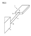
- the heat absorbing member 3 formed as the absorber block 3a is seen without the coil 2 and the core 2a connected to the heat pipe 4 and thermally connected to the cooling plate 5.
- the current flowing through the electrical winding 2 of the reactor 1 generates a magnetic field.
- the heat loss is caused by the current flow in the winding 2 and by the permanent Ummagnetmaschineen in the core 2a.
- the plate 5 is cooled by means of liquid so that between the two ends 4a, 4b of the heat pipe 4, a sufficient temperature difference is present. This causes the heat to be transported by the heat pipe 4 from the heat absorbing member 3a to the plate 5, respectively.
- the element 3a cools down accordingly until the absorbed amount of heat is equal to the amount of heat dissipated by the heat pipe 4.
- FIG. 1 The heat generated in the winding 2 is absorbed by the one (upper) side and the core 2a from the other (lower) side of the element 3 and dissipated via the heat pipe 4.
- the heat removal is preferably only from the core 2a.
- the cooling plate 5 in each case provides the required low temperature level, which is required for the heat dissipation by means of heat pipe 4.
- heat pipe 4 in conjunction with heat-absorbing elements 3 in the form of absorber blocks 3a can be used selectively at critical points. This is required, for example, in the case of output chokes with a high proportion of core losses directly in the center of the core 2a (of the core package), for high-current coils directly in the area between the individual windings or winding layers, but also in the area between winding 2 and core 2a.
Landscapes
- Engineering & Computer Science (AREA)
- Life Sciences & Earth Sciences (AREA)
- Sustainable Development (AREA)
- Physics & Mathematics (AREA)
- Thermal Sciences (AREA)
- Mechanical Engineering (AREA)
- General Engineering & Computer Science (AREA)
- Power Engineering (AREA)
- Transformer Cooling (AREA)
Applications Claiming Priority (1)
| Application Number | Priority Date | Filing Date | Title |
|---|---|---|---|
| DE200810004342 DE102008004342B3 (de) | 2008-01-09 | 2008-01-09 | Anordnung mit mindestens einer elektrischen Wicklung |
Publications (1)
| Publication Number | Publication Date |
|---|---|
| EP2079087A1 true EP2079087A1 (fr) | 2009-07-15 |
Family
ID=40481808
Family Applications (1)
| Application Number | Title | Priority Date | Filing Date |
|---|---|---|---|
| EP09150099A Withdrawn EP2079087A1 (fr) | 2008-01-09 | 2009-01-06 | Agencement doté d'au moins un enroulement électrique |
Country Status (2)
| Country | Link |
|---|---|
| EP (1) | EP2079087A1 (fr) |
| DE (1) | DE102008004342B3 (fr) |
Cited By (5)
| Publication number | Priority date | Publication date | Assignee | Title |
|---|---|---|---|---|
| WO2011038184A1 (fr) * | 2009-09-24 | 2011-03-31 | Parker Hannifin Corporation | Refroidissement intégré de composants électriques bobinés |
| EP2337040A1 (fr) * | 2009-12-18 | 2011-06-22 | ABB Technology AG | Noyau de transformateur |
| CN102889811A (zh) * | 2012-10-24 | 2013-01-23 | 无锡市通和工机有限公司 | 热管式换热器 |
| CN113593840A (zh) * | 2021-06-28 | 2021-11-02 | 南京南瑞继保工程技术有限公司 | 内置冷板的高频变压器 |
| EP4224494A1 (fr) * | 2022-02-03 | 2023-08-09 | Siemens Aktiengesellschaft | Dispositif de refroidissement de produits électriques à enrouler |
Families Citing this family (3)
| Publication number | Priority date | Publication date | Assignee | Title |
|---|---|---|---|---|
| DE102013109535A1 (de) * | 2013-05-07 | 2014-11-13 | Elektro-Bauelemente Gmbh | Einspeisevorrichtung |
| DE202013103599U1 (de) * | 2013-08-09 | 2014-11-13 | Trafomodern Transformatorengesellschaft M.B.H. | Elektrisches Bauteil |
| DE102013217728A1 (de) * | 2013-09-05 | 2015-03-05 | Siemens Aktiengesellschaft | Spulenanordnung |
Citations (7)
| Publication number | Priority date | Publication date | Assignee | Title |
|---|---|---|---|---|
| US3541487A (en) * | 1968-11-18 | 1970-11-17 | Westinghouse Electric Corp | Electrical winding having heat exchangers between layers of the winding for cooling the windings |
| JPS5717116A (en) * | 1980-07-04 | 1982-01-28 | Hitachi Ltd | Resin molded coil |
| JPS60163412A (ja) * | 1984-02-03 | 1985-08-26 | Matsushita Electric Ind Co Ltd | トランス |
| WO1996031888A1 (fr) | 1995-04-06 | 1996-10-10 | Centre D'innovation Sur Le Transport D'energie Du Quebec | Transformateur a isolation a corps solide |
| WO2002102124A2 (fr) * | 2001-06-12 | 2002-12-19 | Liebert Corporation | Systeme de transfert thermique a bus simple ou double |
| EP1641003A2 (fr) | 2004-09-01 | 2006-03-29 | Rockwell Automation Technologies, Inc. | Refroidissement d'un ensemble de bobines pour un composant électrique |
| US20070247266A1 (en) * | 2004-08-10 | 2007-10-25 | Yargole Arun D | Compact Dry Transformer |
-
2008
- 2008-01-09 DE DE200810004342 patent/DE102008004342B3/de not_active Expired - Fee Related
-
2009
- 2009-01-06 EP EP09150099A patent/EP2079087A1/fr not_active Withdrawn
Patent Citations (7)
| Publication number | Priority date | Publication date | Assignee | Title |
|---|---|---|---|---|
| US3541487A (en) * | 1968-11-18 | 1970-11-17 | Westinghouse Electric Corp | Electrical winding having heat exchangers between layers of the winding for cooling the windings |
| JPS5717116A (en) * | 1980-07-04 | 1982-01-28 | Hitachi Ltd | Resin molded coil |
| JPS60163412A (ja) * | 1984-02-03 | 1985-08-26 | Matsushita Electric Ind Co Ltd | トランス |
| WO1996031888A1 (fr) | 1995-04-06 | 1996-10-10 | Centre D'innovation Sur Le Transport D'energie Du Quebec | Transformateur a isolation a corps solide |
| WO2002102124A2 (fr) * | 2001-06-12 | 2002-12-19 | Liebert Corporation | Systeme de transfert thermique a bus simple ou double |
| US20070247266A1 (en) * | 2004-08-10 | 2007-10-25 | Yargole Arun D | Compact Dry Transformer |
| EP1641003A2 (fr) | 2004-09-01 | 2006-03-29 | Rockwell Automation Technologies, Inc. | Refroidissement d'un ensemble de bobines pour un composant électrique |
Cited By (6)
| Publication number | Priority date | Publication date | Assignee | Title |
|---|---|---|---|---|
| WO2011038184A1 (fr) * | 2009-09-24 | 2011-03-31 | Parker Hannifin Corporation | Refroidissement intégré de composants électriques bobinés |
| EP2337040A1 (fr) * | 2009-12-18 | 2011-06-22 | ABB Technology AG | Noyau de transformateur |
| CN102889811A (zh) * | 2012-10-24 | 2013-01-23 | 无锡市通和工机有限公司 | 热管式换热器 |
| CN113593840A (zh) * | 2021-06-28 | 2021-11-02 | 南京南瑞继保工程技术有限公司 | 内置冷板的高频变压器 |
| EP4224494A1 (fr) * | 2022-02-03 | 2023-08-09 | Siemens Aktiengesellschaft | Dispositif de refroidissement de produits électriques à enrouler |
| WO2023148179A1 (fr) * | 2022-02-03 | 2023-08-10 | Siemens Aktiengesellschaft | Dispositif de refroidissement de matériaux d'enroulement électrique |
Also Published As
| Publication number | Publication date |
|---|---|
| DE102008004342B3 (de) | 2009-07-30 |
Similar Documents
| Publication | Publication Date | Title |
|---|---|---|
| DE102008004342B3 (de) | Anordnung mit mindestens einer elektrischen Wicklung | |
| DE102007001234A1 (de) | Halbleiterbaugruppe zum Anschluss an eine Transformatorwicklung und Transformatoranordnung | |
| DE102011013684B4 (de) | Elektrisches Bauteil mit wenigstens einer in einer Vergussmasse angeordneten elektrischen Verlustleistungsquelle und einer Kühleinrichtung | |
| DE3229480A1 (de) | Trockentransformator mit in giessharz eingegossenen wicklungen | |
| DE102004021107A1 (de) | Flüssigkeitskühlung für Eisenkern und Wicklungspakete | |
| DE102011007334A1 (de) | Flüssigkeitsgekühlte induktive Komponente | |
| DE102007001233A1 (de) | Windungselement für eine Spulenwicklung und Transformatoranordnung | |
| CH698904A2 (de) | Wassergekühlte Drossel. | |
| DE102011082045A1 (de) | Drossel und zugehöriges Herstellungsverfahren | |
| DE102009030067A1 (de) | Kühlkörper für eine Drossel oder einen Transformator und Drossel und Transformator mit einem solchen Kühlkörper | |
| DE1913163A1 (de) | Transformator mit Waermeableitkoerper | |
| EP2793244B1 (fr) | Bobine de transformateur à sec et transformateur à sec | |
| EP2751814B1 (fr) | Transformateur et son procédé de fabrication | |
| DE102004012743A1 (de) | Magnetanordnung für Trag-, Führ- und/oder Bremssysteme bei Magnetschwebefahrzeugen | |
| EP1301931A1 (fr) | Inducteur de type i comme microinducteur haute frequence | |
| EP2975618B1 (fr) | Noyau pour un dispositif d'induction électrique | |
| EP2562772A2 (fr) | Elément inductif | |
| DE202005008757U1 (de) | Transformator | |
| EP3510607B1 (fr) | Noyau pour dispositif d'induction électrique | |
| DE102015118652A1 (de) | Spulenanordnung | |
| DE102012217607A1 (de) | Vorrichtung zum Kühlen | |
| EP0106958A1 (fr) | Pompe électrodynamique | |
| DE202013103599U1 (de) | Elektrisches Bauteil | |
| EP2529382B1 (fr) | Commutateur à gradins en charge | |
| EP2337040A1 (fr) | Noyau de transformateur |
Legal Events
| Date | Code | Title | Description |
|---|---|---|---|
| PUAI | Public reference made under article 153(3) epc to a published international application that has entered the european phase |
Free format text: ORIGINAL CODE: 0009012 |
|
| AK | Designated contracting states |
Kind code of ref document: A1 Designated state(s): AT BE BG CH CY CZ DE DK EE ES FI FR GB GR HR HU IE IS IT LI LT LU LV MC MK MT NL NO PL PT RO SE SI SK TR |
|
| AX | Request for extension of the european patent |
Extension state: AL BA RS |
|
| RAP1 | Party data changed (applicant data changed or rights of an application transferred) |
Owner name: MDEXX GMBH |
|
| AKX | Designation fees paid | ||
| STAA | Information on the status of an ep patent application or granted ep patent |
Free format text: STATUS: THE APPLICATION IS DEEMED TO BE WITHDRAWN |
|
| 18D | Application deemed to be withdrawn |
Effective date: 20100116 |
|
| REG | Reference to a national code |
Ref country code: DE Ref legal event code: 8566 |