EP2079129A1 - Antenne réglable pour terminaux de communication sans fil - Google Patents
Antenne réglable pour terminaux de communication sans fil Download PDFInfo
- Publication number
- EP2079129A1 EP2079129A1 EP09157899A EP09157899A EP2079129A1 EP 2079129 A1 EP2079129 A1 EP 2079129A1 EP 09157899 A EP09157899 A EP 09157899A EP 09157899 A EP09157899 A EP 09157899A EP 2079129 A1 EP2079129 A1 EP 2079129A1
- Authority
- EP
- European Patent Office
- Prior art keywords
- switching mechanism
- tuning
- tuning element
- operated
- frequency shift
- Prior art date
- Legal status (The legal status is an assumption and is not a legal conclusion. Google has not performed a legal analysis and makes no representation as to the accuracy of the status listed.)
- Ceased
Links
- 238000004891 communication Methods 0.000 title description 4
- 230000007246 mechanism Effects 0.000 claims abstract description 126
- 230000005540 biological transmission Effects 0.000 claims abstract description 125
- 238000000034 method Methods 0.000 claims description 18
- 230000008878 coupling Effects 0.000 claims description 13
- 238000010168 coupling process Methods 0.000 claims description 13
- 238000005859 coupling reaction Methods 0.000 claims description 13
- 230000001413 cellular effect Effects 0.000 description 2
- 230000007423 decrease Effects 0.000 description 2
- 230000003247 decreasing effect Effects 0.000 description 2
- 238000010295 mobile communication Methods 0.000 description 2
- 238000010521 absorption reaction Methods 0.000 description 1
- 230000002542 deteriorative effect Effects 0.000 description 1
- 230000009977 dual effect Effects 0.000 description 1
- 230000000694 effects Effects 0.000 description 1
- 230000005404 monopole Effects 0.000 description 1
- 238000005549 size reduction Methods 0.000 description 1
Images



Classifications
-
- H—ELECTRICITY
- H01—ELECTRIC ELEMENTS
- H01Q—ANTENNAS, i.e. RADIO AERIALS
- H01Q1/00—Details of, or arrangements associated with, antennas
- H01Q1/36—Structural form of radiating elements, e.g. cone, spiral, umbrella; Particular materials used therewith
- H01Q1/38—Structural form of radiating elements, e.g. cone, spiral, umbrella; Particular materials used therewith formed by a conductive layer on an insulating support
-
- H—ELECTRICITY
- H01—ELECTRIC ELEMENTS
- H01Q—ANTENNAS, i.e. RADIO AERIALS
- H01Q9/00—Electrically-short antennas having dimensions not more than twice the operating wavelength and consisting of conductive active radiating elements
- H01Q9/04—Resonant antennas
- H01Q9/0407—Substantially flat resonant element parallel to ground plane, e.g. patch antenna
- H01Q9/0421—Substantially flat resonant element parallel to ground plane, e.g. patch antenna with a shorting wall or a shorting pin at one end of the element
-
- H—ELECTRICITY
- H01—ELECTRIC ELEMENTS
- H01Q—ANTENNAS, i.e. RADIO AERIALS
- H01Q1/00—Details of, or arrangements associated with, antennas
- H01Q1/12—Supports; Mounting means
- H01Q1/22—Supports; Mounting means by structural association with other equipment or articles
- H01Q1/24—Supports; Mounting means by structural association with other equipment or articles with receiving set
-
- H—ELECTRICITY
- H01—ELECTRIC ELEMENTS
- H01Q—ANTENNAS, i.e. RADIO AERIALS
- H01Q1/00—Details of, or arrangements associated with, antennas
- H01Q1/12—Supports; Mounting means
- H01Q1/22—Supports; Mounting means by structural association with other equipment or articles
- H01Q1/24—Supports; Mounting means by structural association with other equipment or articles with receiving set
- H01Q1/241—Supports; Mounting means by structural association with other equipment or articles with receiving set used in mobile communications, e.g. GSM
- H01Q1/242—Supports; Mounting means by structural association with other equipment or articles with receiving set used in mobile communications, e.g. GSM specially adapted for hand-held use
- H01Q1/243—Supports; Mounting means by structural association with other equipment or articles with receiving set used in mobile communications, e.g. GSM specially adapted for hand-held use with built-in antennas
-
- H—ELECTRICITY
- H01—ELECTRIC ELEMENTS
- H01Q—ANTENNAS, i.e. RADIO AERIALS
- H01Q9/00—Electrically-short antennas having dimensions not more than twice the operating wavelength and consisting of conductive active radiating elements
- H01Q9/04—Resonant antennas
- H01Q9/0407—Substantially flat resonant element parallel to ground plane, e.g. patch antenna
- H01Q9/0442—Substantially flat resonant element parallel to ground plane, e.g. patch antenna with particular tuning means
Definitions
- the present invention relates generally to a radio antenna and, more specifically, to an internal multi-band antenna for use in a hand-held telecommunication device, such as a personal mobile communication terminal (PMCT).
- PMCT personal mobile communication terminal
- the antenna as disclosed in Fayyaz et al ., has a quarter wavelength rectangular patch antenna that is shorted on one end and has a resonant frequency f1.
- a transmission line is added to one edge of the patch that is not parallel to the shorted end of the patch to create two resonant frequencies on either side of f1, while simultaneously removing the resonant frequency f1.
- the antenna of Fayyaz et al . is not tunable.
- Today's standard PMCTs operate at two frequency bands (e.g. E-GMS900/1800 in Europe). It would be desirable to have more universal PMCTs, which can be used in multiple systems around the world.
- the American cellular systems operate at the 850 MHz frequency range (824 - 894 MHz). It is advantageous and desirable to provide a multi-band internal radio antenna for use in a PMCT that is tunable to cover the system bands of both the European and American cellular systems.
- a tunable antenna such as a tunable patch antenna, operating at one or more radio frequency bands. It is a further object of the present invention to provide a tunable antenna, wherein the bandwidth of one or more of the frequency bands can be increased without deteriorating the performance of the antenna at other frequency bands.
- the objects can be achieved by providing one or more reactive tuning components to a resonant type antenna, such as a patch antenna, for tuning the resonant frequency or frequencies of the antenna.
- the tuning components include one or more low-loss transmission line sections of suitable length and termination.
- the tuning components include one or more lumped reactive elements.
- a radio antenna for use in a hand-held telecommunications device has a radiating element having a resonant frequency, a grounding point, and a feed point.
- the antenna is characterized by a transmission line having a length between a first end and an opposing second end, the second end coupled to the radiating element for providing a frequency shift from the resonant frequency, and an adjustment means, disposed adjacent to the first end of the transmission line, for adjusting the frequency shift by effectively changing the length of the transmission line.
- the adjustment means may comprise:
- the adjustment means may comprise:
- the antenna may have a further radiating element having a further resonant frequency.
- the antenna may be further characterized by a further transmission line having a length between a first end and an opposing second end, the second end coupled to the radiating element for providing a further frequency shift from the further resonant frequency, and an adjustment means is further adapted to adjusting the further frequency shift by effectively changing the length of the further transmission line.
- the adjustment means may also comprise:
- a hand-held telecommunications device has a radio antenna having a resonant frequency for communicating with other communication devices, and a chassis with a chassis ground for disposing the radio antenna.
- the antenna is characterized by a radiating element, a feed point, a grounding point connected to the chassis ground, a transmission line having a length between a first end and an opposing second end, the second end coupled to the radiating element for providing a frequency shift from the resonance frequency, and an adjustment means, disposed adjacent to the first end of the transmission line, for adjusting the frequency shift by effectively changing the length of the transmission line.
- the adjustment means may comprise:
- the antenna may have a further a radiating element having a further resonant frequency.
- the antenna may be further characterized by a further transmission line having a length between a first end and an opposing second end, the second end coupled to the radiating element for providing a further frequency shift from the further resonance frequency, and an adjustment means is further adapted to adjusting the further frequency shift by effectively changing the length of the further transmission line.
- a method of tuning a radio antenna for use in a hand-held telecommunications device having a chassis ground wherein the antenna includes a radiating element having a resonant frequency, a grounding point coupled to the chassis ground, and a feed point.
- the method is characterized by the steps of providing a transmission line having a length coupled to the radiating element for providing a frequency shift from the resonant frequency, and providing an adjustment means for adjusting the frequency shift by effectively changing the length of the transmission line.
- the adjustment means comprises:
- the radio antenna also comprises a further a radiating element having a further resonant frequency.
- the method is further characterized by the steps of providing a further transmission line coupled to the radiating element for providing a further frequency shift from the further resonance frequency, and providing a further adjusting mechanism for adjusting the further frequency shift by effectively changing the length of the further transmission line.
- the further adjustment means comprises:
- a radio antenna for use in a hand-held telecommunications device, said antenna including a radiating element having a resonant frequency, a grounding point and a feed point.
- the antenna is characterized by a tuning component having a first end and an opposing second end, the second end coupled to the radiating element for providing a frequency shift from the resonant frequency, and an adjustment means, disposed adjacent to the first end of the tuning component, for adjusting the frequency shift.
- the tuning component comprises a lumped reactive element.
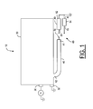
- FIG. 1 shows a schematic representation of an antenna 10, according to the preferred embodiment of the present invention.
- the antenna 10 has a radiating element 20, which is shorted by a grounding pin 32, and a feed line 30.
- the antenna is a low-profile printed antenna, such as a microstrip patch antenna or a planar inverted-F antenna (PIFA), so that the tuning circuit, according to the present invention, can be easily integrated to the antenna.
- PIFA planar inverted-F antenna
- the tuning circuit and the method of tuning, according to present invention can be applied to any other resonant antenna type, such as a simple monopole whip, a dielectric resonator antenna (DRA), or a normal-mode helix.
- a tuning element such as a lumped reactive element or a section of a transmission line 40, has a first end 41 and a second end 42 coupled to the radiating element 20.
- the coupling between the radiating element 40 and the second end 42 of the transmission line 40 can be an ohmic contact or a capacitive coupling, for example. Elements that increase the capacitance between the transmission line 40 and the radiating element 20 can also be used.
- the transmission line 40 may also be an integral part of the radiating element 20. It should be noted that the transmission line 40 shown in Figures 1 to 3 can be coupled to the radiating element 20 in a location, and be shaped in a way, as shown in Figure 4 . However, the coupling location and the shape of the transmission line 40 can be varied for appropriately controlling the electrical coupling between the transmission line 40 and the radiating element 20, and thus the frequency shift.
- an adjustment circuit 60 is used for tuning the resonant frequency of the antenna 10 by effectively changing the length of the transmission line 40.
- the adjustment circuit 60 comprises one or more extension lines 80, 84, and a switching component 70 for linking one of the extension lines 80, 84 to the first end 41 of the transmission line 40.
- the switching component 70 is operable in a first position and a second position, wherein when the switching component 70 is operated in the first position, it provides an electrical coupling between the first end 41 of the transmission line 40 and one of the extension lines 80, 84. When the switching component 70 is operated in the second position, it remains open so as to leave the transmission line 40 and the extension lines 80, 84 uncoupled.
- the switching component 70 can be a PIN-diode, or other switching mechanism. Because the switching component 70 is not directly connected to the radiating element 20, but is separated from it by the transmission line 40, the power loss in the switching component 70 and the transmission line 40 can be reduced.
- a practical figure of merit for the tuning circuit, including the transmission line 40 and adjustment circuit 60, is the ratio of the tuning range over losses ( TRL ). A larger value of TRL means lower losses for a given frequency shift and the tuning circuit is considered better.
- TRL as a function of L T (the length of the transmission line 40 in Figure 1 , for example) and L E (the length of the extension lines 80, 84 in Figure 1 , for example) in both switching states (closed and open)
- L T and L E the length of the extension lines 80, 84 in Figure 1 , for example
- the efficiency (and TRL ) in the open position of the switch is minimized. If L T,eff is increased or decreased from 0.25 ⁇ , the efficiency decreases in the closed position of the switch, but increases rapidly in the open position of the switch.
- L T,eff By adjusting L T,eff , an optimal balance of the efficiencies in the open and closed positions of the switch can be found.
- the optimal balance depends, of course, on the application.
- L T,eff is increased from 0.25 ⁇
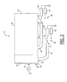
- FIG. 2 is a schematic representation of an antenna 10 having a radiating part 20', which comprises two radiating elements 22, 24 each having a resonant frequency.
- a resonant frequency is subjected to tuning.
- the resonant frequency of the radiating element 22 is lower than the resonant frequency of the radiating element 24 and the tuning is used to adjust the lower frequency
- the length of the transmission line 40 and the extension lines 80, 84 is selected in accordance with the wavelength ⁇ corresponding to the lower resonant frequency. It has been found that coupling the transmission line 40 and the adjustment circuit 60 to the antenna does not considerably deteriorate the performance of the higher frequency component.
- the bandwidth of the antenna can increase. However, both the lower and the upper frequency bands can be effectively widened by way of tuning.
- a further transmission line 50 and a further adjustment circuit 62 are provided for tuning the upper frequency band associated with the resonant frequency of the radiating element 24.
- the transmission line 50 has a first end 51 and a second end 52, which is electrically coupled to the radiating part 20'.
- the adjustment circuit 62 comprises a switching component 72 and one or more extension lines 90 and 94. Similar to the switching component 70, the switching component 72 is operable in a first position for electrically coupling one of the extension lines 90 to the first end 51 of the transmission line 50.
- FIG 4 is an isometric view showing an exemplary configuration of the antenna 10, according to the present invention.
- the antenna 10 is disposed on a chassis 110.
- the chassis 110 has an upper side 112 facing the antenna 10, and a lower side 114 having a ground plane to allow the radiating elements 22 and 24 to be shorted via the ground pin 32.
- the tuning circuit is disposed on the upper side 112 of the chassis 110, separated from the ground plane by a dielectric layer.
- the pin 34 which is used to connect the radiating part 20', is located near the grounding pin 32.
- the sections 122 and 124 on the radiating part 20' are capacitive loads.
- FIG. 5 is a schematic representation of a hand-held telecommunications device 100 having a chassis 110 to implement the antenna 10, according to the present invention.
- the hand-held device 100 can be a personal mobile communication terminal (PMCT), a communicator device, a personal data assistant (PDA) or the like.
- PMCT personal mobile communication terminal
- PDA personal data assistant
- the switching components 70 and 72 can be PIN-diodes, but they can be other switching mechanisms, such as FET switches and MEM (micro-electromechanical) switches.
- two extension lines 80, 84 are used for tuning the radiating part 20, 20', as shown in Figures 1-3 , it is possible to use one extension line or three or more extension lines for tuning.
- the transmission line 40 is connected to the radiating part 20' via a pin 34. It is possible that the coupling between the transmission line 40 and the radiating part 20' is capacitive. Elements that increase the capacitance between the transmission line 40 and the radiating part 20' can be used in the capacitive coupling.
- One or both transmission lines 40, 50, as shown in Figures 1-3 can be totally or partly replaced by lumped reactive elements.
- the element 40 in Figures 1-3 can be a lumped reactive element or the combination of a transmission line and a lumped reactive element.
- one or more of the extension lines 80, 84, 90, 94 can also be replaced by lumped reactive elements.
- extension lines 80, 84, 90 and 94 are not necessarily shorted at one end thereof, as shown in Figures 1-3 . Some or all of the extension lines can be open-circuited, as shown in Figure 6 .
- the switches 70 and 72 are not necessarily connected in series with the extension lines, as shown in Figures 1-3 . The switches can be connected in parallel with the extension lines, as shown in Figure 7a . Even when the extension lines are not short-circuited, as shown in Figure7b , a shunt switch can also be used.
- the performance of the antenna configurations can also be optimized using plots of TRL as a function of L T (the length of the transmission line 40 in Figures 6-7b , for example) and L E (the length of the extension lines 80' in Figures 6-7b , for example) in both switching states (closed and open).
- L T the length of the transmission line 40 in Figures 6-7b
- L E the length of the extension lines 80' in Figures 6-7b , for example
Landscapes
- Engineering & Computer Science (AREA)
- Computer Networks & Wireless Communication (AREA)
- Variable-Direction Aerials And Aerial Arrays (AREA)
- Support Of Aerials (AREA)
Applications Claiming Priority (2)
| Application Number | Priority Date | Filing Date | Title |
|---|---|---|---|
| US10/058,823 US6650295B2 (en) | 2002-01-28 | 2002-01-28 | Tunable antenna for wireless communication terminals |
| EP03701634A EP1470611A4 (fr) | 2002-01-28 | 2003-01-24 | Antenne accordable pour terminaux de communication sans fil |
Related Parent Applications (1)
| Application Number | Title | Priority Date | Filing Date |
|---|---|---|---|
| EP03701634A Division EP1470611A4 (fr) | 2002-01-28 | 2003-01-24 | Antenne accordable pour terminaux de communication sans fil |
Publications (1)
| Publication Number | Publication Date |
|---|---|
| EP2079129A1 true EP2079129A1 (fr) | 2009-07-15 |
Family
ID=27609683
Family Applications (2)
| Application Number | Title | Priority Date | Filing Date |
|---|---|---|---|
| EP09157899A Ceased EP2079129A1 (fr) | 2002-01-28 | 2003-01-24 | Antenne réglable pour terminaux de communication sans fil |
| EP03701634A Withdrawn EP1470611A4 (fr) | 2002-01-28 | 2003-01-24 | Antenne accordable pour terminaux de communication sans fil |
Family Applications After (1)
| Application Number | Title | Priority Date | Filing Date |
|---|---|---|---|
| EP03701634A Withdrawn EP1470611A4 (fr) | 2002-01-28 | 2003-01-24 | Antenne accordable pour terminaux de communication sans fil |
Country Status (6)
| Country | Link |
|---|---|
| US (1) | US6650295B2 (fr) |
| EP (2) | EP2079129A1 (fr) |
| KR (1) | KR100967851B1 (fr) |
| CN (1) | CN100380735C (fr) |
| AU (1) | AU2003202723A1 (fr) |
| WO (1) | WO2003065499A2 (fr) |
Cited By (4)
| Publication number | Priority date | Publication date | Assignee | Title |
|---|---|---|---|---|
| EP1509966A1 (fr) * | 2002-05-31 | 2005-03-02 | Sagem S.A. | Antenne multi-frequence integree pour telephone mobile |
| CN103367874A (zh) * | 2012-04-06 | 2013-10-23 | 宏碁股份有限公司 | 通信装置 |
| DE102018204204A1 (de) * | 2018-03-20 | 2019-09-26 | Geze Gmbh | Drahtloskomponente einer Brandschutz-Feststellanlage oder einer Brandmeldeanlage |
| DE102013114223C5 (de) * | 2013-12-06 | 2026-02-19 | Hörmann KG Antriebstechnik | Fernsteuerbare tür- oder torantriebsvorrichtung mit magnetischer antenne |
Families Citing this family (146)
| Publication number | Priority date | Publication date | Assignee | Title |
|---|---|---|---|---|
| US8744384B2 (en) | 2000-07-20 | 2014-06-03 | Blackberry Limited | Tunable microwave devices with auto-adjusting matching circuit |
| KR20030085000A (ko) * | 2001-03-22 | 2003-11-01 | 텔레폰악티에볼라겟엘엠에릭슨(펍) | 이동 통신 장치 |
| US6836249B2 (en) * | 2002-10-22 | 2004-12-28 | Motorola, Inc. | Reconfigurable antenna for multiband operation |
| US6734825B1 (en) * | 2002-10-28 | 2004-05-11 | The National University Of Singapore | Miniature built-in multiple frequency band antenna |
| US6762723B2 (en) * | 2002-11-08 | 2004-07-13 | Motorola, Inc. | Wireless communication device having multiband antenna |
| US6917335B2 (en) * | 2002-11-08 | 2005-07-12 | Centurion Wireless Technologies, Inc. | Antenna with shorted active and passive planar loops and method of making the same |
| US6933893B2 (en) * | 2002-12-27 | 2005-08-23 | Motorola, Inc. | Electronically tunable planar antenna and method of tuning the same |
| US6876334B2 (en) * | 2003-02-28 | 2005-04-05 | Hong Kong Applied Science And Technology Research Institute Co., Ltd. | Wideband shorted tapered strip antenna |
| US20050219128A1 (en) * | 2004-03-31 | 2005-10-06 | Tan Yu C | Antenna radiator assembly and radio communications device |
| GB0407901D0 (en) * | 2004-04-06 | 2004-05-12 | Koninkl Philips Electronics Nv | Improvements in or relating to planar antennas |
| DE102004026133A1 (de) * | 2004-05-28 | 2005-12-29 | Infineon Technologies Ag | Sendeanordnung, Empfangsanordnung, Transceiver sowie Verfahren zum Betreiben einer Sendeanordnung |
| US6970137B1 (en) * | 2004-06-15 | 2005-11-29 | Nokia Corporation | Method and device for loading planar antennas |
| US7928914B2 (en) * | 2004-06-21 | 2011-04-19 | Motorola Mobility, Inc. | Multi-frequency conductive-strip antenna system |
| CN1989652B (zh) * | 2004-06-28 | 2013-03-13 | 脉冲芬兰有限公司 | 天线部件 |
| US7079079B2 (en) * | 2004-06-30 | 2006-07-18 | Skycross, Inc. | Low profile compact multi-band meanderline loaded antenna |
| JP2006050533A (ja) * | 2004-07-08 | 2006-02-16 | Matsushita Electric Ind Co Ltd | アンテナ装置 |
| US7924226B2 (en) * | 2004-09-27 | 2011-04-12 | Fractus, S.A. | Tunable antenna |
| US7663555B2 (en) * | 2004-10-15 | 2010-02-16 | Sky Cross Inc. | Method and apparatus for adaptively controlling antenna parameters to enhance efficiency and maintain antenna size compactness |
| US7834813B2 (en) * | 2004-10-15 | 2010-11-16 | Skycross, Inc. | Methods and apparatuses for adaptively controlling antenna parameters to enhance efficiency and maintain antenna size compactness |
| US8000737B2 (en) * | 2004-10-15 | 2011-08-16 | Sky Cross, Inc. | Methods and apparatuses for adaptively controlling antenna parameters to enhance efficiency and maintain antenna size compactness |
| FI121520B (fi) * | 2005-02-08 | 2010-12-15 | Pulse Finland Oy | Sisäinen monopoliantenni |
| US8378892B2 (en) | 2005-03-16 | 2013-02-19 | Pulse Finland Oy | Antenna component and methods |
| US7990319B2 (en) * | 2005-04-27 | 2011-08-02 | Epcos Ag | Radio device having antenna arrangement suited for operating over a plurality of bands |
| SE0501502L (sv) * | 2005-06-28 | 2006-10-17 | Amc Centurion Ab | Matningsklämma |
| FI20055420A0 (fi) * | 2005-07-25 | 2005-07-25 | Lk Products Oy | Säädettävä monikaista antenni |
| US20070109203A1 (en) * | 2005-08-05 | 2007-05-17 | Samsung Electro-Mechanics Co., Ltd. | Resonant frequency tunable antenna apparatus |
| KR100714634B1 (ko) * | 2005-08-25 | 2007-05-07 | 삼성전기주식회사 | 공진주파수 가변형 안테나 장치 |
| US7327316B2 (en) * | 2005-09-19 | 2008-02-05 | Tyco Electronics Corporation | Embedded planar inverted F antenna (PIFA) tuned with variable grounding point |
| FI119009B (fi) | 2005-10-03 | 2008-06-13 | Pulse Finland Oy | Monikaistainen antennijärjestelmä |
| FI119535B (fi) * | 2005-10-03 | 2008-12-15 | Pulse Finland Oy | Monikaistainen antennijärjestelmä |
| FI118872B (fi) | 2005-10-10 | 2008-04-15 | Pulse Finland Oy | Sisäinen antenni |
| FI118782B (fi) * | 2005-10-14 | 2008-03-14 | Pulse Finland Oy | Säädettävä antenni |
| US7403161B2 (en) * | 2005-10-14 | 2008-07-22 | Motorola, Inc. | Multiband antenna in a communication device |
| US9406444B2 (en) | 2005-11-14 | 2016-08-02 | Blackberry Limited | Thin film capacitors |
| US8125399B2 (en) | 2006-01-14 | 2012-02-28 | Paratek Microwave, Inc. | Adaptively tunable antennas incorporating an external probe to monitor radiated power |
| US7711337B2 (en) | 2006-01-14 | 2010-05-04 | Paratek Microwave, Inc. | Adaptive impedance matching module (AIMM) control architectures |
| US7667659B2 (en) * | 2006-01-25 | 2010-02-23 | Sky Cross, Inc. | Antenna system for receiving digital video broadcast signals |
| KR100758991B1 (ko) * | 2006-02-03 | 2007-09-17 | 삼성전자주식회사 | Rfid 시스템을 구비한 이동통신 단말기 |
| EP1987564A1 (fr) * | 2006-02-22 | 2008-11-05 | Nokia Corporation | Agencement d'antenne |
| US7869783B2 (en) * | 2006-02-24 | 2011-01-11 | Sky Cross, Inc. | Extended smart antenna system |
| WO2007128340A1 (fr) | 2006-05-04 | 2007-11-15 | Fractus, S.A. | DISPOSITIF PORTABLE SANS FIL COMPRENANT UN RÉCEPTEUR DE radioDIFFUSION INTERNE |
| US7616158B2 (en) * | 2006-05-26 | 2009-11-10 | Hong Kong Applied Science And Technology Research Institute Co., Ltd. | Multi mode antenna system |
| US8618990B2 (en) | 2011-04-13 | 2013-12-31 | Pulse Finland Oy | Wideband antenna and methods |
| US7671804B2 (en) * | 2006-09-05 | 2010-03-02 | Apple Inc. | Tunable antennas for handheld devices |
| US20080062045A1 (en) * | 2006-09-08 | 2008-03-13 | Motorola, Inc. | Communication device with a low profile antenna |
| US8781522B2 (en) * | 2006-11-02 | 2014-07-15 | Qualcomm Incorporated | Adaptable antenna system |
| US20080106471A1 (en) * | 2006-11-07 | 2008-05-08 | Media Tek Inc. | Compact PCB antenna |
| US7535312B2 (en) | 2006-11-08 | 2009-05-19 | Paratek Microwave, Inc. | Adaptive impedance matching apparatus, system and method with improved dynamic range |
| US7714676B2 (en) | 2006-11-08 | 2010-05-11 | Paratek Microwave, Inc. | Adaptive impedance matching apparatus, system and method |
| US8193993B2 (en) * | 2006-11-20 | 2012-06-05 | Motorola Mobility, Inc. | Antenna sub-assembly for electronic device |
| US20080122712A1 (en) * | 2006-11-28 | 2008-05-29 | Agile Rf, Inc. | Tunable antenna including tunable capacitor inserted inside the antenna |
| US7782261B2 (en) * | 2006-12-20 | 2010-08-24 | Nokia Corporation | Antenna arrangement |
| US10211538B2 (en) | 2006-12-28 | 2019-02-19 | Pulse Finland Oy | Directional antenna apparatus and methods |
| US7973730B2 (en) * | 2006-12-29 | 2011-07-05 | Broadcom Corporation | Adjustable integrated circuit antenna structure |
| FI20075269A0 (fi) | 2007-04-19 | 2007-04-19 | Pulse Finland Oy | Menetelmä ja järjestely antennin sovittamiseksi |
| US7917104B2 (en) | 2007-04-23 | 2011-03-29 | Paratek Microwave, Inc. | Techniques for improved adaptive impedance matching |
| US8213886B2 (en) | 2007-05-07 | 2012-07-03 | Paratek Microwave, Inc. | Hybrid techniques for antenna retuning utilizing transmit and receive power information |
| JP5070978B2 (ja) * | 2007-07-31 | 2012-11-14 | 日立電線株式会社 | アンテナおよびそれを備えた携帯端末ならびに電気機器 |
| KR100891623B1 (ko) * | 2007-08-13 | 2009-04-02 | 주식회사 이엠따블유안테나 | 공진 주파수 가변형 안테나 |
| US7812772B2 (en) * | 2007-08-23 | 2010-10-12 | Research In Motion Limited | Antenna, and associated method, for a multi-band radio device |
| US7719470B2 (en) * | 2007-08-23 | 2010-05-18 | Research In Motion Limited | Multi-band antenna, and associated methodology, for a radio communication device |
| EP2028720B1 (fr) | 2007-08-23 | 2012-11-07 | Research In Motion Limited | Antenne multibande et méthodologie associée pour dispositif de communication radio |
| EP2028715A1 (fr) | 2007-08-23 | 2009-02-25 | Research In Motion Limited | Antenne et procédé correspondant pour dispositif radio multibande |
| FI120427B (fi) | 2007-08-30 | 2009-10-15 | Pulse Finland Oy | Säädettävä monikaista-antenni |
| US7679567B2 (en) * | 2007-10-18 | 2010-03-16 | Sony Ericsson Mobile Communications Ab | Antenna with series stub tuning |
| US7991363B2 (en) | 2007-11-14 | 2011-08-02 | Paratek Microwave, Inc. | Tuning matching circuits for transmitter and receiver bands as a function of transmitter metrics |
| US8340714B2 (en) | 2007-12-14 | 2012-12-25 | Microsoft Corporation | Computing device with configurable antenna |
| US20120119955A1 (en) * | 2008-02-28 | 2012-05-17 | Zlatoljub Milosavljevic | Adjustable multiband antenna and methods |
| WO2009155966A1 (fr) * | 2008-06-23 | 2009-12-30 | Nokia Corporation | Ensemble antenne accordable |
| US7834814B2 (en) * | 2008-06-25 | 2010-11-16 | Nokia Corporation | Antenna arrangement |
| JP5009240B2 (ja) * | 2008-06-25 | 2012-08-22 | ソニーモバイルコミュニケーションズ株式会社 | マルチバンドアンテナ及び無線通信端末 |
| US7642972B1 (en) * | 2008-07-21 | 2010-01-05 | Cheng Uei Precision Industry Co., Ltd. | Antenna |
| US8072285B2 (en) | 2008-09-24 | 2011-12-06 | Paratek Microwave, Inc. | Methods for tuning an adaptive impedance matching network with a look-up table |
| US8344962B2 (en) * | 2008-11-20 | 2013-01-01 | Nokia Corporation | Apparatus, method and computer program for wireless communication |
| TW201029264A (en) * | 2009-01-23 | 2010-08-01 | Wistron Corp | Electronic device and antenna module |
| US20100231461A1 (en) * | 2009-03-13 | 2010-09-16 | Qualcomm Incorporated | Frequency selective multi-band antenna for wireless communication devices |
| US8472888B2 (en) | 2009-08-25 | 2013-06-25 | Research In Motion Rf, Inc. | Method and apparatus for calibrating a communication device |
| KR20110030113A (ko) | 2009-09-17 | 2011-03-23 | 삼성전자주식회사 | 무선 통신 시스템에서 멀티밴드 안테나 및 그 동작 주파수를 조절하는 장치 및 방법 |
| US9026062B2 (en) | 2009-10-10 | 2015-05-05 | Blackberry Limited | Method and apparatus for managing operations of a communication device |
| FI20096134A0 (fi) * | 2009-11-03 | 2009-11-03 | Pulse Finland Oy | Säädettävä antenni |
| FI20096251A0 (sv) | 2009-11-27 | 2009-11-27 | Pulse Finland Oy | MIMO-antenn |
| JP2011120071A (ja) * | 2009-12-04 | 2011-06-16 | Panasonic Corp | 携帯無線機 |
| US8847833B2 (en) | 2009-12-29 | 2014-09-30 | Pulse Finland Oy | Loop resonator apparatus and methods for enhanced field control |
| FI20105158A7 (fi) | 2010-02-18 | 2011-08-19 | Pulse Finland Oy | Kuorisäteilijällä varustettu antenni |
| US8803631B2 (en) | 2010-03-22 | 2014-08-12 | Blackberry Limited | Method and apparatus for adapting a variable impedance network |
| WO2011133657A2 (fr) | 2010-04-20 | 2011-10-27 | Paratek Microwave, Inc. | Procédé et appareil permettant de gérer l'interférence dans un dispositif de communication |
| US9406998B2 (en) | 2010-04-21 | 2016-08-02 | Pulse Finland Oy | Distributed multiband antenna and methods |
| US9379454B2 (en) | 2010-11-08 | 2016-06-28 | Blackberry Limited | Method and apparatus for tuning antennas in a communication device |
| FI20115072A0 (fi) | 2011-01-25 | 2011-01-25 | Pulse Finland Oy | Moniresonanssiantenni, -antennimoduuli ja radiolaite |
| US9673507B2 (en) | 2011-02-11 | 2017-06-06 | Pulse Finland Oy | Chassis-excited antenna apparatus and methods |
| US8648752B2 (en) | 2011-02-11 | 2014-02-11 | Pulse Finland Oy | Chassis-excited antenna apparatus and methods |
| US8712340B2 (en) | 2011-02-18 | 2014-04-29 | Blackberry Limited | Method and apparatus for radio antenna frequency tuning |
| US8655286B2 (en) | 2011-02-25 | 2014-02-18 | Blackberry Limited | Method and apparatus for tuning a communication device |
| US8594584B2 (en) | 2011-05-16 | 2013-11-26 | Blackberry Limited | Method and apparatus for tuning a communication device |
| US8626083B2 (en) | 2011-05-16 | 2014-01-07 | Blackberry Limited | Method and apparatus for tuning a communication device |
| US8866689B2 (en) | 2011-07-07 | 2014-10-21 | Pulse Finland Oy | Multi-band antenna and methods for long term evolution wireless system |
| US9450291B2 (en) | 2011-07-25 | 2016-09-20 | Pulse Finland Oy | Multiband slot loop antenna apparatus and methods |
| TWI483471B (zh) * | 2011-08-02 | 2015-05-01 | Arcadyan Technology Corp | 雙頻天線 |
| US9769826B2 (en) | 2011-08-05 | 2017-09-19 | Blackberry Limited | Method and apparatus for band tuning in a communication device |
| US9123990B2 (en) | 2011-10-07 | 2015-09-01 | Pulse Finland Oy | Multi-feed antenna apparatus and methods |
| US9531058B2 (en) | 2011-12-20 | 2016-12-27 | Pulse Finland Oy | Loosely-coupled radio antenna apparatus and methods |
| US9484619B2 (en) | 2011-12-21 | 2016-11-01 | Pulse Finland Oy | Switchable diversity antenna apparatus and methods |
| KR101357724B1 (ko) * | 2011-12-29 | 2014-02-03 | 주식회사 바켄 | 다중 대역 안테나 장치 |
| US8988296B2 (en) | 2012-04-04 | 2015-03-24 | Pulse Finland Oy | Compact polarized antenna and methods |
| TWI515963B (zh) * | 2012-04-23 | 2016-01-01 | 和碩聯合科技股份有限公司 | 天線模組及其輻射效率調整方法 |
| US8948889B2 (en) | 2012-06-01 | 2015-02-03 | Blackberry Limited | Methods and apparatus for tuning circuit components of a communication device |
| US10096910B2 (en) * | 2012-06-13 | 2018-10-09 | Skycross Co., Ltd. | Multimode antenna structures and methods thereof |
| US9853363B2 (en) | 2012-07-06 | 2017-12-26 | Blackberry Limited | Methods and apparatus to control mutual coupling between antennas |
| US9246223B2 (en) | 2012-07-17 | 2016-01-26 | Blackberry Limited | Antenna tuning for multiband operation |
| US9413066B2 (en) | 2012-07-19 | 2016-08-09 | Blackberry Limited | Method and apparatus for beam forming and antenna tuning in a communication device |
| US9350405B2 (en) | 2012-07-19 | 2016-05-24 | Blackberry Limited | Method and apparatus for antenna tuning and power consumption management in a communication device |
| US9362891B2 (en) | 2012-07-26 | 2016-06-07 | Blackberry Limited | Methods and apparatus for tuning a communication device |
| US9979078B2 (en) | 2012-10-25 | 2018-05-22 | Pulse Finland Oy | Modular cell antenna apparatus and methods |
| US10069209B2 (en) | 2012-11-06 | 2018-09-04 | Pulse Finland Oy | Capacitively coupled antenna apparatus and methods |
| US9374113B2 (en) | 2012-12-21 | 2016-06-21 | Blackberry Limited | Method and apparatus for adjusting the timing of radio antenna tuning |
| US10404295B2 (en) | 2012-12-21 | 2019-09-03 | Blackberry Limited | Method and apparatus for adjusting the timing of radio antenna tuning |
| KR101372140B1 (ko) * | 2013-01-25 | 2014-03-07 | 엘지이노텍 주식회사 | 안테나 장치 및 그의 급전 구조체 |
| US10079428B2 (en) | 2013-03-11 | 2018-09-18 | Pulse Finland Oy | Coupled antenna structure and methods |
| US9647338B2 (en) | 2013-03-11 | 2017-05-09 | Pulse Finland Oy | Coupled antenna structure and methods |
| US9559433B2 (en) | 2013-03-18 | 2017-01-31 | Apple Inc. | Antenna system having two antennas and three ports |
| US9331397B2 (en) | 2013-03-18 | 2016-05-03 | Apple Inc. | Tunable antenna with slot-based parasitic element |
| US9293828B2 (en) | 2013-03-27 | 2016-03-22 | Apple Inc. | Antenna system with tuning from coupled antenna |
| US9444130B2 (en) | 2013-04-10 | 2016-09-13 | Apple Inc. | Antenna system with return path tuning and loop element |
| US9236930B2 (en) | 2013-06-13 | 2016-01-12 | Nokia Technologies Oy | Methods and apparatus for antenna tuning |
| US9634383B2 (en) | 2013-06-26 | 2017-04-25 | Pulse Finland Oy | Galvanically separated non-interacting antenna sector apparatus and methods |
| US9680212B2 (en) | 2013-11-20 | 2017-06-13 | Pulse Finland Oy | Capacitive grounding methods and apparatus for mobile devices |
| US9590308B2 (en) | 2013-12-03 | 2017-03-07 | Pulse Electronics, Inc. | Reduced surface area antenna apparatus and mobile communications devices incorporating the same |
| KR20150069795A (ko) * | 2013-12-16 | 2015-06-24 | 삼성전자주식회사 | 안테나 장치 및 그것을 갖는 통신 장치 |
| US9350081B2 (en) | 2014-01-14 | 2016-05-24 | Pulse Finland Oy | Switchable multi-radiator high band antenna apparatus |
| US10305167B2 (en) * | 2014-04-29 | 2019-05-28 | Huawei Device Co., Ltd. | Antenna circuit, terminal device, and method for disposing antenna circuit |
| US9948002B2 (en) | 2014-08-26 | 2018-04-17 | Pulse Finland Oy | Antenna apparatus with an integrated proximity sensor and methods |
| US9973228B2 (en) | 2014-08-26 | 2018-05-15 | Pulse Finland Oy | Antenna apparatus with an integrated proximity sensor and methods |
| US9722308B2 (en) | 2014-08-28 | 2017-08-01 | Pulse Finland Oy | Low passive intermodulation distributed antenna system for multiple-input multiple-output systems and methods of use |
| US9438319B2 (en) | 2014-12-16 | 2016-09-06 | Blackberry Limited | Method and apparatus for antenna selection |
| US9906260B2 (en) | 2015-07-30 | 2018-02-27 | Pulse Finland Oy | Sensor-based closed loop antenna swapping apparatus and methods |
| CN105720368B (zh) * | 2016-01-21 | 2018-10-19 | 青岛大学 | 一种射频开关式紧凑型多频段手机天线 |
| TWI606640B (zh) * | 2016-02-26 | 2017-11-21 | 致伸科技股份有限公司 | 天線結構以及應用該天線結構的電路模組與電子裝置 |
| CN107181061B (zh) * | 2016-03-09 | 2020-12-04 | 致伸科技股份有限公司 | 天线结构以及应用该天线结构的电路模块与电子装置 |
| CN106252854B (zh) * | 2016-09-29 | 2019-05-24 | 努比亚技术有限公司 | 一种天线和移动终端 |
| USD824885S1 (en) * | 2017-02-25 | 2018-08-07 | Airgain Incorporated | Multiple antennas assembly |
| US10804617B2 (en) * | 2017-09-11 | 2020-10-13 | Apple Inc. | Electronic devices having shared antenna structures and split return paths |
| CN107967026B (zh) * | 2017-11-23 | 2019-10-25 | Oppo广东移动通信有限公司 | 天线组件、终端设备及改善天线辐射性能的方法 |
| CN107968252A (zh) * | 2017-11-30 | 2018-04-27 | 维沃移动通信有限公司 | 一种天线装置及移动终端 |
| CN110380189A (zh) * | 2019-07-23 | 2019-10-25 | 广东以诺通讯有限公司 | 一种小型化天线及终端 |
| CN113113757B (zh) * | 2021-04-13 | 2023-06-06 | 福耀玻璃工业集团股份有限公司 | 车窗和车辆 |
| US12149012B1 (en) | 2024-04-11 | 2024-11-19 | Geotab Inc. | Multi-band antenna device and tuning techniques |
Citations (9)
| Publication number | Priority date | Publication date | Assignee | Title |
|---|---|---|---|---|
| US4259670A (en) * | 1978-05-16 | 1981-03-31 | Ball Corporation | Broadband microstrip antenna with automatically progressively shortened resonant dimensions with respect to increasing frequency of operation |
| US4751513A (en) * | 1986-05-02 | 1988-06-14 | Rca Corporation | Light controlled antennas |
| EP0630069A1 (fr) * | 1992-12-07 | 1994-12-21 | Ntt Mobile Communications Network Inc. | Antenne |
| JPH09307344A (ja) * | 1996-05-13 | 1997-11-28 | Matsushita Electric Ind Co Ltd | 平面アンテナ |
| US6034636A (en) * | 1996-08-21 | 2000-03-07 | Nec Corporation | Planar antenna achieving a wide frequency range and a radio apparatus used therewith |
| EP0993070A1 (fr) * | 1998-09-30 | 2000-04-12 | Nec Corporation | Antenne en F inverse avec impédance commutée |
| EP0997974A1 (fr) | 1998-10-30 | 2000-05-03 | Lk-Products Oy | Antenne plane avec deux fréquences de résonance |
| US6140966A (en) | 1997-07-08 | 2000-10-31 | Nokia Mobile Phones Limited | Double resonance antenna structure for several frequency ranges |
| EP1113524A2 (fr) * | 1999-12-30 | 2001-07-04 | Nokia Mobile Phones Ltd. | Structure d'antenne, méthode pour coupler un signal sur la structure d antenne, unité d'antenne et station mobile avec une telle structure d'antenne |
Family Cites Families (8)
| Publication number | Priority date | Publication date | Assignee | Title |
|---|---|---|---|---|
| US5309163A (en) * | 1991-09-12 | 1994-05-03 | Trw Inc. | Active patch antenna transmitter |
| US5414434A (en) * | 1993-08-24 | 1995-05-09 | Raytheon Company | Patch coupled aperature array antenna |
| US5394159A (en) * | 1993-11-02 | 1995-02-28 | At&T Corp. | Microstrip patch antenna with embedded detector |
| EP0741467A2 (fr) | 1995-04-25 | 1996-11-06 | AT&T IPM Corp. | Procédé et dispositif pour le réglage dans un réseau de radiotransmission |
| US5943016A (en) * | 1995-12-07 | 1999-08-24 | Atlantic Aerospace Electronics, Corp. | Tunable microstrip patch antenna and feed network therefor |
| WO2001029927A1 (fr) * | 1999-10-15 | 2001-04-26 | Siemens Aktiengesellschaft | Antenne commutable |
| US6501427B1 (en) * | 2001-07-31 | 2002-12-31 | E-Tenna Corporation | Tunable patch antenna |
| DE60331214D1 (de) * | 2002-09-13 | 2010-03-25 | Ricoh Kk | Aufladevorrichtung mit Aufladerolle und und hiermit versehenes Bilderzeugungsgerät |
-
2002
- 2002-01-28 US US10/058,823 patent/US6650295B2/en not_active Expired - Lifetime
-
2003
- 2003-01-24 EP EP09157899A patent/EP2079129A1/fr not_active Ceased
- 2003-01-24 AU AU2003202723A patent/AU2003202723A1/en not_active Abandoned
- 2003-01-24 CN CNB038027488A patent/CN100380735C/zh not_active Expired - Fee Related
- 2003-01-24 KR KR1020047011556A patent/KR100967851B1/ko not_active Expired - Fee Related
- 2003-01-24 EP EP03701634A patent/EP1470611A4/fr not_active Withdrawn
- 2003-01-24 WO PCT/IB2003/000187 patent/WO2003065499A2/fr not_active Ceased
Patent Citations (9)
| Publication number | Priority date | Publication date | Assignee | Title |
|---|---|---|---|---|
| US4259670A (en) * | 1978-05-16 | 1981-03-31 | Ball Corporation | Broadband microstrip antenna with automatically progressively shortened resonant dimensions with respect to increasing frequency of operation |
| US4751513A (en) * | 1986-05-02 | 1988-06-14 | Rca Corporation | Light controlled antennas |
| EP0630069A1 (fr) * | 1992-12-07 | 1994-12-21 | Ntt Mobile Communications Network Inc. | Antenne |
| JPH09307344A (ja) * | 1996-05-13 | 1997-11-28 | Matsushita Electric Ind Co Ltd | 平面アンテナ |
| US6034636A (en) * | 1996-08-21 | 2000-03-07 | Nec Corporation | Planar antenna achieving a wide frequency range and a radio apparatus used therewith |
| US6140966A (en) | 1997-07-08 | 2000-10-31 | Nokia Mobile Phones Limited | Double resonance antenna structure for several frequency ranges |
| EP0993070A1 (fr) * | 1998-09-30 | 2000-04-12 | Nec Corporation | Antenne en F inverse avec impédance commutée |
| EP0997974A1 (fr) | 1998-10-30 | 2000-05-03 | Lk-Products Oy | Antenne plane avec deux fréquences de résonance |
| EP1113524A2 (fr) * | 1999-12-30 | 2001-07-04 | Nokia Mobile Phones Ltd. | Structure d'antenne, méthode pour coupler un signal sur la structure d antenne, unité d'antenne et station mobile avec une telle structure d'antenne |
Non-Patent Citations (5)
| Title |
|---|
| FAYYAZ ET AL.: "A novel Dual Band Patch Antenna for GSM", PROCEEDINGS IEEE-APS CONFERENCE ON ANTENNAS AND PROPAGATION FOR WIRLESS COMMUNICATIONS, pages 156 - 159 |
| FAYYAZ N ET AL: "A novel dual-band patch antenna for GSM band", ANTENNAS AND PROPAGATION FOR WIRELESS COMMUNICATIONS, 1998. 1998 IEEE-APS CONFERENCE ON WALTHAM, MA, USA 1-4 NOV. 1998, NEW YORK, NY, USA,IEEE, US, 1 November 1998 (1998-11-01), pages 156 - 159, XP010313957, ISBN: 0-7803-4955-5 * |
| LIU ET AL., DUAL-FREQUENCY PLANAR INVERTED-F ANTENNA, IEEE TRANSACTION ON ANTENNAS AND PROPAGATION, vol. 45, no. 10, October 1997 (1997-10-01), pages 1451 - 1458 |
| LIU ET AL., DUAL-FREQUENCY PLANAR INVERTED-F ANTENNA, IEEE TRANSACTIONS ON ANTENNAS AND PROPAGATION, vol. 45, 10 October 1997 (1997-10-10), pages 1451 - 1458 |
| SONG ET AL., TRIPLE-BAND PLANAR INVERTED-F ANTENNA, IEEE ANTENNAS AND PROPAGATION INTERNATIONAL SYMPOSIUM DIGEST, vol. 2, 11 July 1999 (1999-07-11), pages 908 - 911 |
Cited By (5)
| Publication number | Priority date | Publication date | Assignee | Title |
|---|---|---|---|---|
| EP1509966A1 (fr) * | 2002-05-31 | 2005-03-02 | Sagem S.A. | Antenne multi-frequence integree pour telephone mobile |
| CN103367874A (zh) * | 2012-04-06 | 2013-10-23 | 宏碁股份有限公司 | 通信装置 |
| CN103367874B (zh) * | 2012-04-06 | 2016-08-03 | 宏碁股份有限公司 | 通信装置 |
| DE102013114223C5 (de) * | 2013-12-06 | 2026-02-19 | Hörmann KG Antriebstechnik | Fernsteuerbare tür- oder torantriebsvorrichtung mit magnetischer antenne |
| DE102018204204A1 (de) * | 2018-03-20 | 2019-09-26 | Geze Gmbh | Drahtloskomponente einer Brandschutz-Feststellanlage oder einer Brandmeldeanlage |
Also Published As
| Publication number | Publication date |
|---|---|
| US20030142022A1 (en) | 2003-07-31 |
| CN100380735C (zh) | 2008-04-09 |
| AU2003202723A1 (en) | 2003-09-02 |
| WO2003065499A2 (fr) | 2003-08-07 |
| US6650295B2 (en) | 2003-11-18 |
| KR20040081148A (ko) | 2004-09-20 |
| CN1623250A (zh) | 2005-06-01 |
| KR100967851B1 (ko) | 2010-07-05 |
| EP1470611A4 (fr) | 2006-06-07 |
| WO2003065499A3 (fr) | 2003-12-24 |
| EP1470611A2 (fr) | 2004-10-27 |
Similar Documents
| Publication | Publication Date | Title |
|---|---|---|
| US6650295B2 (en) | Tunable antenna for wireless communication terminals | |
| KR100993439B1 (ko) | 안테나 장치 및 무선 통신 장치 | |
| EP1368855B1 (fr) | Configuration d'antenne | |
| KR101054713B1 (ko) | 다중대역 다중모드 콤팩트 안테나 시스템 | |
| EP1296410B1 (fr) | Antenne multibande interne | |
| US6980154B2 (en) | Planar inverted F antennas including current nulls between feed and ground couplings and related communications devices | |
| US7696928B2 (en) | Systems and methods for using parasitic elements for controlling antenna resonances | |
| EP2942834B1 (fr) | Appareil d'antenne et dispositif terminal | |
| US10601114B2 (en) | Multi-part radio apparatus | |
| EP1368857A1 (fr) | Arrangement d'antenne multibande pour appareil de communications radio | |
| WO2004057697A2 (fr) | Antenne a commutation de frequence rapide | |
| US20080150828A1 (en) | Antenna arrangement | |
| US8378900B2 (en) | Antenna arrangement | |
| Yoon et al. | A frequency-selecting technique for mobile handset antennas based on capacitance switching | |
| Zhong | A coupled-fed reconfigurable antenna for internal LTE mobile phone applications | |
| KR20020087139A (ko) | 무선 단말기 | |
| KR100611908B1 (ko) | 이중패치를 이용한 평면 안테나를 구비한 무선통신 단말기 | |
| Li et al. | Six‐band internal antenna for small‐size mobile phone | |
| EP2270925A1 (fr) | Dispositif d'antenne et dispositif de communication radio portable comportant un tel dispositif d'antenne |
Legal Events
| Date | Code | Title | Description |
|---|---|---|---|
| PUAI | Public reference made under article 153(3) epc to a published international application that has entered the european phase |
Free format text: ORIGINAL CODE: 0009012 |
|
| 17P | Request for examination filed |
Effective date: 20090414 |
|
| AC | Divisional application: reference to earlier application |
Ref document number: 1470611 Country of ref document: EP Kind code of ref document: P |
|
| AK | Designated contracting states |
Kind code of ref document: A1 Designated state(s): AT BE BG CH CY CZ DE DK EE ES FI FR GB GR HU IE IT LI LU MC NL PT SE SI SK TR |
|
| 17Q | First examination report despatched |
Effective date: 20090817 |
|
| STAA | Information on the status of an ep patent application or granted ep patent |
Free format text: STATUS: THE APPLICATION HAS BEEN REFUSED |
|
| 18R | Application refused |
Effective date: 20101105 |