EP2079142A1 - Bloc-batterie rechargeable - Google Patents
Bloc-batterie rechargeable Download PDFInfo
- Publication number
- EP2079142A1 EP2079142A1 EP08150163A EP08150163A EP2079142A1 EP 2079142 A1 EP2079142 A1 EP 2079142A1 EP 08150163 A EP08150163 A EP 08150163A EP 08150163 A EP08150163 A EP 08150163A EP 2079142 A1 EP2079142 A1 EP 2079142A1
- Authority
- EP
- European Patent Office
- Prior art keywords
- switching device
- battery pack
- electronic switching
- rechargeable battery
- power cell
- Prior art date
- Legal status (The legal status is an assumption and is not a legal conclusion. Google has not performed a legal analysis and makes no representation as to the accuracy of the status listed.)
- Granted
Links
Images
Classifications
-
- H—ELECTRICITY
- H02—GENERATION; CONVERSION OR DISTRIBUTION OF ELECTRIC POWER
- H02J—ELECTRIC POWER NETWORKS; CIRCUIT ARRANGEMENTS OR SYSTEMS FOR SUPPLYING OR DISTRIBUTING ELECTRIC POWER; SYSTEMS FOR STORING ELECTRIC ENERGY
- H02J7/00—Circuit arrangements for charging or discharging batteries or for supplying loads from batteries
- H02J7/60—Circuit arrangements for charging or discharging batteries or for supplying loads from batteries including safety or protection arrangements
- H02J7/663—Circuit arrangements for charging or discharging batteries or for supplying loads from batteries including safety or protection arrangements using battery or load disconnect circuits
-
- H—ELECTRICITY
- H01—ELECTRIC ELEMENTS
- H01M—PROCESSES OR MEANS, e.g. BATTERIES, FOR THE DIRECT CONVERSION OF CHEMICAL ENERGY INTO ELECTRICAL ENERGY
- H01M10/00—Secondary cells; Manufacture thereof
- H01M10/42—Methods or arrangements for servicing or maintenance of secondary cells or secondary half-cells
- H01M10/44—Methods for charging or discharging
-
- H—ELECTRICITY
- H01—ELECTRIC ELEMENTS
- H01M—PROCESSES OR MEANS, e.g. BATTERIES, FOR THE DIRECT CONVERSION OF CHEMICAL ENERGY INTO ELECTRICAL ENERGY
- H01M10/00—Secondary cells; Manufacture thereof
- H01M10/42—Methods or arrangements for servicing or maintenance of secondary cells or secondary half-cells
- H01M10/44—Methods for charging or discharging
- H01M10/443—Methods for charging or discharging in response to temperature
-
- H—ELECTRICITY
- H02—GENERATION; CONVERSION OR DISTRIBUTION OF ELECTRIC POWER
- H02J—ELECTRIC POWER NETWORKS; CIRCUIT ARRANGEMENTS OR SYSTEMS FOR SUPPLYING OR DISTRIBUTING ELECTRIC POWER; SYSTEMS FOR STORING ELECTRIC ENERGY
- H02J7/00—Circuit arrangements for charging or discharging batteries or for supplying loads from batteries
- H02J7/60—Circuit arrangements for charging or discharging batteries or for supplying loads from batteries including safety or protection arrangements
- H02J7/64—Circuit arrangements for charging or discharging batteries or for supplying loads from batteries including safety or protection arrangements against overvoltage
-
- H—ELECTRICITY
- H02—GENERATION; CONVERSION OR DISTRIBUTION OF ELECTRIC POWER
- H02J—ELECTRIC POWER NETWORKS; CIRCUIT ARRANGEMENTS OR SYSTEMS FOR SUPPLYING OR DISTRIBUTING ELECTRIC POWER; SYSTEMS FOR STORING ELECTRIC ENERGY
- H02J7/00—Circuit arrangements for charging or discharging batteries or for supplying loads from batteries
- H02J7/60—Circuit arrangements for charging or discharging batteries or for supplying loads from batteries including safety or protection arrangements
- H02J7/65—Circuit arrangements for charging or discharging batteries or for supplying loads from batteries including safety or protection arrangements against overtemperature
-
- H—ELECTRICITY
- H01—ELECTRIC ELEMENTS
- H01M—PROCESSES OR MEANS, e.g. BATTERIES, FOR THE DIRECT CONVERSION OF CHEMICAL ENERGY INTO ELECTRICAL ENERGY
- H01M10/00—Secondary cells; Manufacture thereof
- H01M10/05—Accumulators with non-aqueous electrolyte
- H01M10/052—Li-accumulators
- H01M10/0525—Rocking-chair batteries, i.e. batteries with lithium insertion or intercalation in both electrodes; Lithium-ion batteries
-
- H—ELECTRICITY
- H02—GENERATION; CONVERSION OR DISTRIBUTION OF ELECTRIC POWER
- H02J—ELECTRIC POWER NETWORKS; CIRCUIT ARRANGEMENTS OR SYSTEMS FOR SUPPLYING OR DISTRIBUTING ELECTRIC POWER; SYSTEMS FOR STORING ELECTRIC ENERGY
- H02J7/00—Circuit arrangements for charging or discharging batteries or for supplying loads from batteries
- H02J7/60—Circuit arrangements for charging or discharging batteries or for supplying loads from batteries including safety or protection arrangements
- H02J7/62—Circuit arrangements for charging or discharging batteries or for supplying loads from batteries including safety or protection arrangements against overcurrent
-
- Y—GENERAL TAGGING OF NEW TECHNOLOGICAL DEVELOPMENTS; GENERAL TAGGING OF CROSS-SECTIONAL TECHNOLOGIES SPANNING OVER SEVERAL SECTIONS OF THE IPC; TECHNICAL SUBJECTS COVERED BY FORMER USPC CROSS-REFERENCE ART COLLECTIONS [XRACs] AND DIGESTS
- Y02—TECHNOLOGIES OR APPLICATIONS FOR MITIGATION OR ADAPTATION AGAINST CLIMATE CHANGE
- Y02E—REDUCTION OF GREENHOUSE GAS [GHG] EMISSIONS, RELATED TO ENERGY GENERATION, TRANSMISSION OR DISTRIBUTION
- Y02E60/00—Enabling technologies; Technologies with a potential or indirect contribution to GHG emissions mitigation
- Y02E60/10—Energy storage using batteries
Definitions
- the embodiments described herein relate generally to rechargeable battery packs, and in particular to a method of reducing the equivalent series resistance (ESR) of a rechargeable battery pack, such as a Li-Ion battery pack, without sacrificing safety.
- ESR equivalent series resistance
- Rechargeable battery packs such as Li-Ion battery packs
- PDAs personal digital assistants
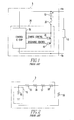
- FIG 1 is a schematic diagram of a prior art rechargeable battery pack 5, such as a Li-Ion battery pack, that may be used to provide power to a passive load 10, such as a cell phone or a PDA.
- the passive load 10 is supplanted by an active element such as a battery charger, which can recharge the rechargeable battery pack 5.
- the rechargeable battery pack 5 includes a power cell 15, such as a Li-Ion cell, a thermal protector 20 and a protection circuit module (PCM) 25 driving the load 10.
- PCM protection circuit module
- the PCM 25 includes an integrated circuit control chip 30 operatively coupled to one or more electronic switching devices 35 and 40, which in Figure 1 are modeled as MOSFETs.
- the PCM 25 is essentially a switch that detects abnormal currents and/or voltages and disconnects the cell 15 from the load 10, or, alternatively, a charger if the rechargeable battery pack 5 is being charged.
- the thermal protector 20 provides protection for the rechargeable battery pack 5 from overtemperature conditions. Overtemperature conditions can have any of several causes or combinations of causes. Overtemperature conditions can damage or impair electronic components such as those in the load 10. In the event of an overtemperature condition, it may be desirable to substantially reduce current, and thereby substantially reduce delivered power, to the load 10, thereby reducing the risk of damage or impairment.
- the thermal protector 20 may be, for example, a thermal fuse, a thermal breaker or a positive temperature coefficient (PTC) thermistor. Thermal protector 20 may also be either non-resettable or resettable. Non-resettable thermal protectors have lower equivalent series resistance (ESR), but once tripped, a rechargeable battery pack employing the non-resettable thermal protector is essentially no longer of any use. Resettable thermal protectors have higher ESRs, but can be tripped and reset many times.
- ESR equivalent series resistance
- ESR is one of the main parameters determining the usable energy stored in the cell 15, and thus the usable energy stored in the rechargeable battery pack 5.
- Lower ESR in general, means longer operation such as longer talk times for a cell phone.
- the ESR thereof includes the internal resistance of the cell 15, the resistance of the thermal protector 20, the resistance of the electronic switching devices 35 and 40, and the resistance of any connectors and other conductors in the circuit path to the load 10.
- the thermal protector 20 adds to the ESR of the rechargeable battery pack 5, and the resistance of the thermal protector 20 is not negligible.
- the circuit control chip 30 is not in the circuit path that includes the cell 15, the thermal protector 20 and the load 10, and does not significantly contribute to the ESR.
- Figure 2 is a schematic diagram of an equivalent conceptual circuit of the rechargeable battery pack 5 that shows each of the resistance components which add to the ESR of the rechargeable battery pack 5.
- the equivalent circuit includes a resistor 50 that represents the resistance of the cell 15, a resistor 55 that represents the resistance of the thermal protector 20, resistors 56 and 57 that represent the resistance of the electronic switching devices 35 and 40, and a resistor 58 that represents the resistance of the connectors and other conductors in the circuit path to the load 10 (which is represented by the resistor 59).
- ESR is one of the main parameters determining the usable energy in a rechargeable battery pack
- FIG 1 is a schematic diagram of a prior art rechargeable battery pack, such as a Li-Ion battery pack, that may be used to provide power to a load, such as a cell phone or a PDA;
- a prior art rechargeable battery pack such as a Li-Ion battery pack
- a load such as a cell phone or a PDA
- Figure 2 is a schematic diagram of an equivalent conceptual circuit of the rechargeable battery pack shown in Figure 1 ;
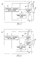
- Figure 3 is a schematic diagram of a rechargeable battery pack
- Figure 4 is a schematic diagram of an alternate embodiment of a rechargeable battery pack
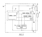
- Figure 5 is a schematic diagram of a rechargeable battery pack showing a switching configuration in more detail.
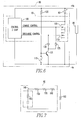
- Figure 6 is a schematic diagram of a rechargeable battery pack showing in further detail one embodiment of the rechargeable battery pack
- Figure 7 is a schematic illustration of an equivalent conceptual circuit for the rechargeable battery pack shown in Figure 6 .
- FIG. 3 is a schematic diagram of a rechargeable battery pack 60 according to one aspect of the disclosed embodiments.
- the rechargeable battery pack 60 provides power to a load 68 (between the upper and lower power supply rails, denoted as +Ve and -Ve) and includes a power cell 64, such as one or more Li-Ion cells. (Use of the term "battery" pack is not intended to indicate that more than one power cell 64 is necessarily employed, although in various embodiments, more than one power cell may be employed.)
- the rechargeable battery pack 60 further includes circuitry 61 that monitors for overvoltage and/or overcurrent conditions, and thermal protection circuitry 62 that monitors for overtemperature conditions.
- the rechargeable battery pack 60 also includes an electronic switch 66.
- the electronic switch is coupled to the power cell 64 such that substantially all of the current passing through the power cell 64 also passes through the electronic switch 66.
- An arrow 69 shows the direction of positive current flow in a loop that includes the power cell 64, the load 68 and the electronic switch 66. When the load 68 is supplanted by a charger, the direction of positive current flow 69 in the loop is reversed.
- circuit loops that include the overvoltage/overcurrent circuitry 61 and the thermal protection circuitry 62. These currents, however, are negligible in comparison to the current in the loop that includes the power cell 64, the load 68 and the electronic switch 66. Under normal operation, the electronic switch 66 is "ON," that is, in a conducting condition in which it can conduct current.
- the overvoltage/overcurrent circuitry 61 and the thermal protection circuitry 62 are operatively coupled to the electronic switch 66 such that the overvoltage/overcurrent circuitry 61 and the thermal protection circuitry 62 can each independently cause the electronic switch 66 to assume an "OFF" or non-conducting condition, in which the electronic switch 66 will not conduct current.
- the electronic switch 66 is OFF, the loop that includes the power cell 64, the load 68 and the electronic switch 66 is effectively made open, thereby preventing the power cell 64 from supplying current to the load 68.
- Figure 4 is a schematic diagram similar to Figure 3 .
- the overvoltage/overcurrent circuitry 61 and the thermal protection circuitry 62 each controls an electronic switch.
- the overvoltage/overcurrent circuitry 61 controls electronic switch 66A and the thermal protection circuitry 62 controls electronic switch 66B.
- the electronic switches 66A and 66B can independently be controlled to become OFF and assume a non-conducting condition. When either electronic switch 66A or 66B is in a non-conducting condition, the power cell 64 is prevented from supplying current to the load 68.
- FIG. 5 is a schematic diagram of a rechargeable battery pack 70 according to another aspect of the disclosed embodiments.
- the rechargeable battery pack 70 provides power to a load 78 between the upper and lower power supply rails +Ve and -Ve, and includes a power cell 74, such as one or more Li-Ion cells.
- the rechargeable battery pack 70 further includes circuitry 75 that monitors for overvoltage and/or overcurrent conditions, and thermal protection circuitry 72 that monitors for overtemperature conditions. In operation, when the temperature within the rechargeable battery pack 70 exceeds some predetermined threshold level, one or more circuit elements in the thermal protection circuitry 72 will be caused to trip, thereby triggering a change in operation of the thermal protection circuitry 72.
- the overvoltage/overcurrent circuitry 75 is similar to PCM 25 in Figure 1 , and includes an integrated circuit control chip 73 operatively coupled to one or more electronic switching devices 76A and 76B, which in Figure 5 are modeled as MOSFETs.
- the integrated circuit control chip 73 is configured to supply a voltage to a controlling terminal of the electronic switching devices 76A and 76B, particularly, the gates of electronic switching devices 76A and 76B, causing the electronic switching devices 76A and 76B to be ON during normal operation.
- Either the integrated circuit control chip 73 or the thermal protection circuitry 72 can independently cause the electronic switching devices 76A or 76B, or both, to turn OFF.
- An arrow 79 shows the direction of positive current flow in a loop that includes the power cell 74, the load 78 and the electronic switches 76A and 76B.
- the loop current 79 effectively goes to zero.
- the electronic switch 76A is directed to charge control and the electronic switch 76B is directed to discharge control.
- Separate electronic switches to control discharge (in which the direction of positive current flow is in the direction shown by arrow 79) and charge (in which the direction of positive current flow is in the direction opposite that shown by arrow 79) are advantageous in that some transistors are more effective in cutting off current flow in particular directions. As a result, two electronic switches are better able to cut off current flow regardless of the direction of current flow 79.
- This disclosure does not require, however, that separate electronic switches be provided for charge and discharge.
- FIG 6 is a schematic diagram of a rechargeable battery pack 80, such as a Li-Ion battery pack, according to one aspect of the disclosed embodiments, which has a reduced ESR without sacrificing safety.
- the rechargeable battery pack 80 provides power to a load 85 between the power supply rails +Ve and -Ve and includes a power cell 90, such as one or more Li-Ion cells, and a PCM 95.
- the PCM 95 includes an integrated circuit control chip 100 operatively coupled to electronic switching devices 105 and 110, which are modeled in Figure 6 as MOSFETs but which may comprise any electronic switching component or circuitry under the control of the integrated circuit control chip 100.
- the power cell 90 is coupled to the electronic switching devices 105 and 110 such that substantially all current passing through the power cell 90 also passes through the electronic switching devices 105 and 110.
- the electronic switching devices 105 and 110 are ON, the electronic switching devices 105 and 110 are in a conducting condition, and current passes through the power cell 90.
- the electronic switching devices 105 and 110 are OFF, the electronic switching devices 105 and 110 are in a non-conducting condition, and effectively no current passes through the power cell 90, thereby cutting off the power cell 90 as a power source for load 85.
- the power cell 90 may continue to deliver current to other electronic components, such as the PCM 95, when the electronic switching devices 105 and 110 are OFF. These other currents, however, are negligible in comparison to currents passing through the load 85 under normal operating conditions. In a typical implementation, over ninety-nine percent of the current passing through the power cell 90 would pass through the load 85, and less than one percent would pass through other components of rechargeable battery pack 80. In other words, substantially all of the current passing through the power cell 90 passes through the load 85, and substantially all of the current passing through the power cell 90 also passes through the electronic switching devices 105 and 110.
- Whether the electronic switching devices 105 and 110 are ON or OFF is under the control of integrated circuit control chip 100, which is responsive to overvoltage and over current conditions. As discussed below, however, whether the electronic switching devices 105 and 110 are OFF can also be controlled by thermal protection circuitry that is responsive to overtemperature conditions. Concerns about overvoltages, overcurrents and overtemperature conditions are similar whether cell 90 is supplying power during ordinary operation or consuming power during recharging (although overvoltage is generally not a problem when the power cell 90 is coupled to a passive load 85, but overvoltage can be a concern during recharging). For simplicity, the focus below will assume that the cell 90 is supplying power to the passive load 85.
- the rechargeable battery pack 80 further includes a thermal protector 115 for providing overtemperature protection for the rechargeable battery pack 80.
- the thermal protector 115 is not provided in the circuit path that includes the cell 90 and the switching devices 105 and 110 for providing power to the load 85. Rather, the thermal protector 115 is removed from that circuit path and instead is, as shown in Figure 6 , provided in a separate circuit path.
- the thermal protector 115 may be, for example, a thermal fuse, a thermal breaker or a positive temperature coefficient (PTC) thermistor. Because the thermal protector 115 is not provided in the circuit path to the load 85, it does not add to the ESR of the rechargeable battery pack 80, thereby reducing the ESR as compared to the prior art rechargeable battery pack 5 shown in Figure 1 .
- PTC positive temperature coefficient
- the resistor 120 is provided to bias the electronic switching device 125 ON when the thermal protector 115 trips and the impedance of the thermal protector 115 goes from low to high.
- the resistor 120 is further sized to have a large impedance in comparison to the load 85, such that most current passing through the cell 90 will pass through the load 85, and the current flowing through the thermal protector 115 will be comparatively low.
- the impedance of the load 85 would be in the range of a few ohms.
- the resistor by comparison, might be sized in the range of tens of thousands of ohms, such as fifty thousand ohms.
- Current flowing through the load 85 is in the range of several amperes, and current flowing through the resistor 120 is in the range of millionths of an ampere.
- Current flowing through the integrated circuit control chip 100 is also very small in comparison to current flowing through the load 85 under normal operating conditions. As a result, currents flowing through other loops in rechargeable battery pack 80 are negligible in comparison to current flowing through the load 85.
- currents passing through the cell 90 may not be of the same magnitudes as in the case when the cell 90 is supplying power to a passive load, but currents supplied to the overvoltage/overcurrent circuitry and the thermal protection circuitry generally remain negligible, and substantially all of the current supplied by the charger passes through the cell 90 and the electronic switching devices 105 and 110.
- the electronic switching device 125 in Figure 6 is modeled as an NPN bi-polar junction transistor, but electronic switching device 125 can also be realized as a PNP bi-polar junction transistor, or other transistor or combination of transistors.
- the electronic switching device 125 turns ON, it robs the drive to the switching devices 105 and 110, and they turn OFF, thereby cutting off the load 85 from the cell 90.
- the thermal protector 115 in ON (operating normally), the electronic switching device 125 cannot be biased ON since the thermal protector 115 itself is robbing the bias from the base of the electronic switching device 125.
- the thermal protector 115 is operatively coupled to the electronic switching devices 105 and 110 through the electronic switching device 125 and the diodes 130 and 135.
- the thermal protector 115 will be caused to trip.
- the electronic switching devices 105 and 110 are caused to turn OFF (assume a non-conducting condition), effectively interrupting the current path from the power cell 90 through the load 85.
- the electronic switching devices 105 and 110 are controlled by the outputs of the integrated circuit control chip 100 to be ON, the electronic switching device 125 is OFF, and effectively no current flows into the collector node (where the junction of the cathodes of the two diodes 130 and 135 connect) because the collector-to-emitter connection behaves like an open circuit.
- the two diodes 130 and 135 are essentially out of the picture, because the diodes 130 and 135 are not conducting and behave like open circuits.
- the electronic switching device 125 is OFF because the thermal protector 115 in ON (typically at a relatively low impedance).
- thermal protector 115 robs the base drive current flowing through the resistor 120, effectively bypassing the base of electronic switching device 125.
- the thermal protector 115 trips due to a high temperature, the impedance of the thermal protector 115 changes from a low impedance to a high impedance.
- Current now flows through the resistor 120 to the base of electronic switching device 125.
- the electronic switching device 125 turns ON, driving the collector voltage down, close to the emitter voltage.
- the voltage at the collector node, to which the cathodes of the diodes 130 and 135 are connected is also driven low.
- the diodes 130 and 135 turn ON and conduct current.
- the implementation described herein effectively causes the control electronic switching devices 105 and 110 of the PCM 95 to act as temperature-dependent switches (on top of their other duties in the PCM 95 as required by the integrated circuit control chip 100).
- the temperature cutoff protection provided by the thermal protector 115 is independent, meaning that it is not under the control of any controller or processor, and in particular not under the control of the integrated circuit control chip 100.
- a thermal protector 115 can be utilized that has a very high impedance during normal temperature conditions, and a low impedance during overtemperature conditions.
- the electronic switching device 125 can be eliminated and the thermal protector 115 can be directly coupled between the lower power rail and the cathodes of the diodes 130 and 135.
- the impedance of the thermal protector 115 is high, and virtually no current is able to flow through the thermal protector 115. As a result, the diodes 130 and 135 are OFF.
- the impedance of the thermal protector 115 is low, effectively pulling down the cathode voltage of the diodes 130 and 135, turning them ON and turning OFF the electronic switching devices 105 and 110.
- the thermal protector 115 can serve both as a temperature-sensitive element and as a switching element to turn ON diodes 130 and 135.
- FIG. 7 is a schematic illustration of an equivalent conceptual circuit 140 for the rechargeable battery pack 80.
- the equivalent circuit 140 includes a resistor 145 that represents the resistance of the cell 90, resistors 150 and 155 that represent the resistance of the electronic switching devices 105 and 110, and a resistor 160 that represents the resistance of connectors and other conductors in the series path to the load 85 (which is represented by the resistor 165).
- the circuit path that includes the cell 90 and the electronic switching devices 105 and 110, which provide power to the load 85 does not include any resistance that is attributable to the thermal protector 115, because any resistance that is attributable to the thermal protector 115 is negligible.
- nearly all current passing through the 90 cell passes through the load 85, while a much smaller and comparatively insignificant amount of current flows through the thermal protector 115 and other circuit elements.
- the circuit described above may realize one or more advantages. Because the thermal protector 115 is not provided in the circuit path that includes the cell 90 and the load 85 and because the circuit path that includes the resistor 120 and the thermal protector 115 has a comparably higher impedance, very low currents will flow through the thermal protector 115. This disclosure is not limited to any particular amount of current flowing through thermal protector 115, but in general, the amount of current flowing through thermal protector 115 is negligible, such that thermal protector 115 has a negligible effect upon the ESR. Because very low currents will flow through the thermal protector 115, a smaller, typically less expensive component can be utilized as the thermal protector 115.
- the thermal protector 115 is a positive temperature coefficient (PTC) thermistor
- PTC positive temperature coefficient
- the effect of residual high post-trip resistance will not add to the ESR of the rechargeable battery pack 80.
- the resistance of a PTC thermistor never quite relaxes back to its original level, but rather settles at a higher level (this is the high post-trip resistance cited above).
- PTC thermistor is used in the circuit path that includes a cell in a rechargeable battery, as is the case in the rechargeable battery pack 5 of Figure 1 , the fact that post-trip resistance is increased adds to the ESR of the battery pack 5 in Figure 1 .
- An increased post-trip resistance in the configuration of Figure 6 would not necessarily result in a corresponding increase in ESR.
- the rechargeable battery pack 80 provides a reduced ESR, and therefore increased battery time. Increased battery time results in increased device usage time between chargings. Further, the configuration depicted in Figure 6 protects against overvoltage, overcurrent and overtemperture conditions, thereby effectively preserving the safety of the rechargeable battery pack 80.
- circuit elements depicted as directly coupled may be coupled via one or more intermediate elements, such as a resistor or diode.
- intermediate elements such as a resistor or diode.
- the electronic switching devices 105 and 110 in Figure 6 could be coupled via resistors to the integrated circuit control chip 100. Accordingly, these and other embodiments are within the scope of the following claims.
Landscapes
- Engineering & Computer Science (AREA)
- Power Engineering (AREA)
- Manufacturing & Machinery (AREA)
- Chemical & Material Sciences (AREA)
- Chemical Kinetics & Catalysis (AREA)
- Electrochemistry (AREA)
- General Chemical & Material Sciences (AREA)
- Protection Of Static Devices (AREA)
- Charge And Discharge Circuits For Batteries Or The Like (AREA)
Priority Applications (6)
| Application Number | Priority Date | Filing Date | Title |
|---|---|---|---|
| DE602008002808T DE602008002808D1 (de) | 2008-01-10 | 2008-01-10 | Akku mit einer thermischen Schutzschaltung |
| EP08150163A EP2079142B1 (fr) | 2008-01-10 | 2008-01-10 | Bloc-batterie rechargeable avec un circuit de protection thermique |
| AT08150163T ATE483269T1 (de) | 2008-01-10 | 2008-01-10 | Akku mit einer thermischen schutzschaltung |
| US11/972,214 US7956581B2 (en) | 2008-01-10 | 2008-01-10 | Rechargeable battery pack |
| CA2648610A CA2648610C (fr) | 2008-01-10 | 2009-01-09 | Bloc-batterie rechargeable |
| US13/089,896 US8026696B2 (en) | 2008-01-10 | 2011-04-19 | Rechargeable battery pack |
Applications Claiming Priority (2)
| Application Number | Priority Date | Filing Date | Title |
|---|---|---|---|
| EP08150163A EP2079142B1 (fr) | 2008-01-10 | 2008-01-10 | Bloc-batterie rechargeable avec un circuit de protection thermique |
| US11/972,214 US7956581B2 (en) | 2008-01-10 | 2008-01-10 | Rechargeable battery pack |
Publications (2)
| Publication Number | Publication Date |
|---|---|
| EP2079142A1 true EP2079142A1 (fr) | 2009-07-15 |
| EP2079142B1 EP2079142B1 (fr) | 2010-09-29 |
Family
ID=50550121
Family Applications (1)
| Application Number | Title | Priority Date | Filing Date |
|---|---|---|---|
| EP08150163A Active EP2079142B1 (fr) | 2008-01-10 | 2008-01-10 | Bloc-batterie rechargeable avec un circuit de protection thermique |
Country Status (5)
| Country | Link |
|---|---|
| US (2) | US7956581B2 (fr) |
| EP (1) | EP2079142B1 (fr) |
| AT (1) | ATE483269T1 (fr) |
| CA (1) | CA2648610C (fr) |
| DE (1) | DE602008002808D1 (fr) |
Cited By (5)
| Publication number | Priority date | Publication date | Assignee | Title |
|---|---|---|---|---|
| WO2016016620A1 (fr) * | 2014-07-29 | 2016-02-04 | Nicoventures Holdings Limited | Cigarette electronique et bloc de recharge |
| EP3282544A1 (fr) * | 2014-01-13 | 2018-02-14 | Littelfuse, Inc. | Protection de batterie secondaire avec désactivation permanente |
| US10218193B2 (en) | 2014-07-29 | 2019-02-26 | Nicoventures Holdings Limited | E-cigarette and re-charging pack |
| CN113270853A (zh) * | 2018-12-21 | 2021-08-17 | 荣耀终端有限公司 | 电池保护电路、电池保护板、电池和终端设备 |
| EP3920362A4 (fr) * | 2019-01-31 | 2022-03-30 | Vivo Mobile Communication Co., Ltd. | Circuit de charge et dispositif électronique |
Families Citing this family (16)
| Publication number | Priority date | Publication date | Assignee | Title |
|---|---|---|---|---|
| US8102154B2 (en) * | 2008-09-04 | 2012-01-24 | Medtronic Minimed, Inc. | Energy source isolation and protection circuit for an electronic device |
| TWI383167B (zh) * | 2008-09-23 | 2013-01-21 | 緯創資通股份有限公司 | 檢測一電源儲存裝置之運作情形的方法及其相關電源儲存裝置 |
| WO2011014597A2 (fr) | 2009-07-31 | 2011-02-03 | Thermo King Corporation | Convertisseur de tension de batterie bidirectionnel |
| JP5428675B2 (ja) * | 2009-09-09 | 2014-02-26 | 株式会社リコー | 二次電池の保護回路、バッテリーパック及び電子機器 |
| JP2011142789A (ja) * | 2010-01-08 | 2011-07-21 | Seiko Instruments Inc | 電池パック |
| KR101108188B1 (ko) * | 2010-06-10 | 2013-03-08 | 삼성에스디아이 주식회사 | 배터리 보호회로 및 이의 제어방법 |
| US8649140B2 (en) | 2011-03-04 | 2014-02-11 | Electrochem Solutions, Inc. | Voltage activated 2nd level safety circuit for permanent isolation |
| WO2014045745A1 (fr) * | 2012-09-18 | 2014-03-27 | Necエナジーデバイス株式会社 | Système de stockage d'énergie et procédé de protection de batterie |
| JP5937050B2 (ja) * | 2013-10-25 | 2016-06-22 | 横河電機株式会社 | 充電回路 |
| JP6221685B2 (ja) * | 2013-11-25 | 2017-11-01 | ミツミ電機株式会社 | 二次電池の保護回路、電池保護モジュール、電池パック及び処理方法 |
| CN104753034B (zh) * | 2013-12-27 | 2018-10-12 | 富泰华工业(深圳)有限公司 | 电子装置及其充电保护电路 |
| DE102014200640A1 (de) * | 2014-01-16 | 2015-07-30 | Robert Bosch Gmbh | Batteriesystem und Verfahren zur Trennung eines Batteriesystems von einem angeschlossenen elektrischen Verbraucher |
| KR102394741B1 (ko) * | 2018-11-29 | 2022-05-06 | 주식회사 엘지에너지솔루션 | 열 방출이 개선된 배터리 모듈, 이러한 배터리 모듈을 포함하는 배터리 팩 및 이러한 배터리 팩을 포함하는 자동차 |
| CN114388904B (zh) * | 2021-12-13 | 2024-11-22 | 西安奇点能源股份有限公司 | 锂离子电池热失控抑制电路及锂离子电池热失控抑制方法 |
| CN115966793B (zh) * | 2022-12-26 | 2024-11-29 | 深圳华晓科技有限公司 | 一种低温条件下锂电池充放电控制方法及装置 |
| CN118713242B (zh) * | 2024-06-07 | 2025-01-07 | 东莞航电新能源科技有限公司 | 锂电池控制电路及摄像头电池仓 |
Citations (3)
| Publication number | Priority date | Publication date | Assignee | Title |
|---|---|---|---|---|
| US5625273A (en) * | 1994-12-30 | 1997-04-29 | Bren-Tronics Inc. | Battery safety device |
| EP1551088A1 (fr) | 2002-10-09 | 2005-07-06 | Sony Chemicals Corp. | Accumulateur avec circuit de protection |
| EP1868274A1 (fr) | 2006-02-27 | 2007-12-19 | Sony Corporation | Batterie independante et son dispositif de protection |
Family Cites Families (27)
| Publication number | Priority date | Publication date | Assignee | Title |
|---|---|---|---|---|
| US5563496A (en) * | 1990-12-11 | 1996-10-08 | Span, Inc. | Battery monitoring and charging control unit |
| EP0644642A3 (fr) * | 1993-07-30 | 1995-05-24 | Texas Instruments Inc | Alimentation électrique. |
| KR100193736B1 (ko) * | 1996-09-17 | 1999-06-15 | 윤종용 | 배터리 보호 기능을 갖는 배터리 팩 |
| US6331763B1 (en) * | 1998-04-15 | 2001-12-18 | Tyco Electronics Corporation | Devices and methods for protection of rechargeable elements |
| DE60045183D1 (de) * | 1999-05-17 | 2010-12-16 | Panasonic Corp | Schaltung und vorrichtung zum schutz einer sekundärbatterie |
| JP3431867B2 (ja) * | 1999-09-21 | 2003-07-28 | 松下電器産業株式会社 | 電池電源装置及びこれを用いた電動機器 |
| US6804100B2 (en) * | 1999-12-31 | 2004-10-12 | Nokia Mobile Phones, Ltd. | Method and apparatus for protection of batteries |
| EP1150413A3 (fr) * | 2000-04-28 | 2005-06-01 | Sony Corporation | Bloc de batteries et système de transmission de signal |
| JP4744673B2 (ja) * | 2000-06-30 | 2011-08-10 | パナソニック株式会社 | 充電装置、電池パック及びそれらを用いた充電システム |
| JP4566392B2 (ja) * | 2000-11-16 | 2010-10-20 | レノボ シンガポール プライヴェート リミテッド | 温度制御に伴うアクションレベルを決定する電池、電池パック、コンピュータ装置、電気機器、および電池の温度制御方法 |
| US7323848B2 (en) * | 2002-12-11 | 2008-01-29 | Japan Storage Battery Co., Ltd. | Battery charging state arithmetic operation device for calculating charging state of battery, and battery charging state arithmetic operation method |
| KR100497374B1 (ko) * | 2002-12-13 | 2005-06-28 | 삼성전자주식회사 | 개인 휴대 통신 단말기의 내장형 배터리 제어장치 |
| JP4186052B2 (ja) * | 2003-03-26 | 2008-11-26 | ミツミ電機株式会社 | 充電制御機能付き電池パック |
| US6819083B1 (en) * | 2003-04-25 | 2004-11-16 | Motorola, Inc. | Dual use thermistor for battery cell thermal protection and battery pack overcharge/undercharge protection |
| JP2007520180A (ja) * | 2003-10-14 | 2007-07-19 | ブラック アンド デッカー インク | 電池パックの障害状態からの保護を提供するべく適合された二次電池、電動工具、充電器、及び電池パック用の保護方法、保護回路、及び保護装置 |
| US7456614B2 (en) * | 2003-10-27 | 2008-11-25 | Sony Corporation | Battery pack |
| JP2005160169A (ja) * | 2003-11-21 | 2005-06-16 | Texas Instr Japan Ltd | バッテリ保護回路 |
| JP4079871B2 (ja) * | 2003-12-17 | 2008-04-23 | 三洋電機株式会社 | パック電池 |
| JP4278622B2 (ja) * | 2004-03-18 | 2009-06-17 | 三洋電機株式会社 | 電源装置 |
| US20050212483A1 (en) * | 2004-03-24 | 2005-09-29 | Wenman Li | Charging/discharging management system for lithium battery packs |
| WO2005124964A1 (fr) * | 2004-06-16 | 2005-12-29 | Murata Manufacturing Co., Ltd. | Circuit de protection de paquet de batteries et paquet de batteries |
| DE102004031601A1 (de) * | 2004-06-30 | 2006-02-09 | Hilti Ag | Akkupack für Elektrohandwerkzeugmaschine |
| US20060119322A1 (en) * | 2004-12-04 | 2006-06-08 | Hossein Maleki | Battery pack with temperature activated boost |
| KR100686794B1 (ko) * | 2005-01-25 | 2007-02-23 | 삼성에스디아이 주식회사 | 배터리팩의 모니터링 장치 및 그 방법 |
| JP4882235B2 (ja) * | 2005-01-27 | 2012-02-22 | ミツミ電機株式会社 | 電池保護用モジュール |
| JP4245571B2 (ja) * | 2005-02-09 | 2009-03-25 | Necエレクトロニクス株式会社 | 充電制御回路及び充電装置 |
| US7808212B2 (en) * | 2006-07-24 | 2010-10-05 | Research In Motion Limited | Temperature-based charge and discharge control for a battery |
-
2008
- 2008-01-10 EP EP08150163A patent/EP2079142B1/fr active Active
- 2008-01-10 US US11/972,214 patent/US7956581B2/en active Active
- 2008-01-10 AT AT08150163T patent/ATE483269T1/de not_active IP Right Cessation
- 2008-01-10 DE DE602008002808T patent/DE602008002808D1/de active Active
-
2009
- 2009-01-09 CA CA2648610A patent/CA2648610C/fr active Active
-
2011
- 2011-04-19 US US13/089,896 patent/US8026696B2/en active Active
Patent Citations (3)
| Publication number | Priority date | Publication date | Assignee | Title |
|---|---|---|---|---|
| US5625273A (en) * | 1994-12-30 | 1997-04-29 | Bren-Tronics Inc. | Battery safety device |
| EP1551088A1 (fr) | 2002-10-09 | 2005-07-06 | Sony Chemicals Corp. | Accumulateur avec circuit de protection |
| EP1868274A1 (fr) | 2006-02-27 | 2007-12-19 | Sony Corporation | Batterie independante et son dispositif de protection |
Cited By (20)
| Publication number | Priority date | Publication date | Assignee | Title |
|---|---|---|---|---|
| EP3282544A1 (fr) * | 2014-01-13 | 2018-02-14 | Littelfuse, Inc. | Protection de batterie secondaire avec désactivation permanente |
| EP3745524A1 (fr) * | 2014-07-29 | 2020-12-02 | Nicoventures Holdings Limited | Cigarette électronique et bloc de recharge |
| US10873196B2 (en) | 2014-07-29 | 2020-12-22 | Nicoventures Holdings Limited | E-cigarette and re-charging pack |
| CN106575877A (zh) * | 2014-07-29 | 2017-04-19 | 尼科创业控股有限公司 | 电子烟和再充电包装 |
| WO2016016620A1 (fr) * | 2014-07-29 | 2016-02-04 | Nicoventures Holdings Limited | Cigarette electronique et bloc de recharge |
| RU2681208C2 (ru) * | 2014-07-29 | 2019-03-05 | Никовенчерс Холдингз Лимитед | Электронная сигарета и заряжаемый контейнер |
| RU2682333C2 (ru) * | 2014-07-29 | 2019-03-19 | Никовенчерс Холдингз Лимитед | Электронная сигарета и перезаряжаемая упаковка сигарет |
| US10276898B2 (en) * | 2014-07-29 | 2019-04-30 | Nicoventures Holdings Limited | E-cigarette and re-charging pack |
| US10536013B2 (en) | 2014-07-29 | 2020-01-14 | Nicoventures Holdings Limited | E-cigarette and re-charging pack |
| US20170207499A1 (en) * | 2014-07-29 | 2017-07-20 | Nicoventures Holdings Limited | E-cigarette and re-charging pack |
| EP3175507B1 (fr) | 2014-07-29 | 2020-09-02 | Nicoventures Holdings Limited | Cigarette electronique et bloc de recharge |
| US10218193B2 (en) | 2014-07-29 | 2019-02-26 | Nicoventures Holdings Limited | E-cigarette and re-charging pack |
| US12095052B2 (en) | 2014-07-29 | 2024-09-17 | Nicoventures Trading Limited | E-cigarette and re-charging pack |
| EP4340170A3 (fr) * | 2014-07-29 | 2024-04-17 | Nicoventures Trading Limited | Cigarette électronique et bloc de recharge |
| US11811027B2 (en) | 2014-07-29 | 2023-11-07 | Nicoventures Trading Limited | E-cigarette and re-charging pack |
| US11831155B2 (en) | 2014-07-29 | 2023-11-28 | Nicoventures Trading Limited | E-cigarette and re-charging pack |
| US11962143B2 (en) | 2018-12-21 | 2024-04-16 | Honor Device Co., Ltd. | Battery protection circuit, battery protection board, battery, and terminal device |
| CN113270853A (zh) * | 2018-12-21 | 2021-08-17 | 荣耀终端有限公司 | 电池保护电路、电池保护板、电池和终端设备 |
| EP3920362A4 (fr) * | 2019-01-31 | 2022-03-30 | Vivo Mobile Communication Co., Ltd. | Circuit de charge et dispositif électronique |
| US12046932B2 (en) | 2019-01-31 | 2024-07-23 | Vivo Mobile Communication Co., Ltd. | Charging circuit and electronic device |
Also Published As
| Publication number | Publication date |
|---|---|
| US8026696B2 (en) | 2011-09-27 |
| DE602008002808D1 (de) | 2010-11-11 |
| US7956581B2 (en) | 2011-06-07 |
| EP2079142B1 (fr) | 2010-09-29 |
| CA2648610C (fr) | 2011-06-14 |
| US20110193530A1 (en) | 2011-08-11 |
| ATE483269T1 (de) | 2010-10-15 |
| CA2648610A1 (fr) | 2009-07-10 |
| US20090179618A1 (en) | 2009-07-16 |
Similar Documents
| Publication | Publication Date | Title |
|---|---|---|
| US7956581B2 (en) | Rechargeable battery pack | |
| EP1181760B1 (fr) | Dispositifs et procedes de protection d'elements rechargeables | |
| US9130383B2 (en) | Charging/discharging control device, battery pack, electrical equipment, and charging/discharging control method | |
| US6300750B1 (en) | Shunt voltage regulator with self-contained thermal crowbar safety protection | |
| US7079003B2 (en) | Secondary battery with protective circuit | |
| US8193774B2 (en) | Battery pack | |
| JP2009183141A (ja) | 再充電可能な素子の保護のための装置および方法 | |
| US6118641A (en) | Overcurrent protection device | |
| JP5376641B2 (ja) | 電池装置 | |
| CN102064541A (zh) | 用于保护可充电元件的装置及方法 | |
| US20120224289A1 (en) | Voltage activated 2nd level safety circuit for permanent isolation | |
| KR20140025674A (ko) | 전기 자동차용 파워 릴레이 어셈블리 및 파워 릴레이 어셈블리가 구비된 전기자동차용 에너지 시스템의 작동 방법 | |
| US20240297512A1 (en) | Battery management system | |
| JP2004515197A (ja) | 充電器回路 | |
| JP2006121827A (ja) | 二次電池の保護回路 | |
| KR20160035798A (ko) | 전지 보호 회로, 전지 보호 장치 및 전지팩 및 전지 보호 방법 | |
| JP4999004B2 (ja) | 二次電池用保護回路およびこの二次電池用保護回路を備えた電池パック | |
| WO2004070908A1 (fr) | Cellule secondaire a resistance de derivation et procede de protection de cellule secondaire | |
| CN116264407A (zh) | 硅氧负极电池的保护电路及硅氧负极电池 | |
| JPH08149701A (ja) | 二次電池の過電流保護装置 |
Legal Events
| Date | Code | Title | Description |
|---|---|---|---|
| PUAI | Public reference made under article 153(3) epc to a published international application that has entered the european phase |
Free format text: ORIGINAL CODE: 0009012 |
|
| 17P | Request for examination filed |
Effective date: 20080111 |
|
| AK | Designated contracting states |
Kind code of ref document: A1 Designated state(s): AT BE BG CH CY CZ DE DK EE ES FI FR GB GR HR HU IE IS IT LI LT LU LV MC MT NL NO PL PT RO SE SI SK TR |
|
| AX | Request for extension of the european patent |
Extension state: AL BA MK RS |
|
| RIN1 | Information on inventor provided before grant (corrected) |
Inventor name: LITINGTUN, SIONG |
|
| RIN1 | Information on inventor provided before grant (corrected) |
Inventor name: LITINGTUN, SIONG |
|
| AKX | Designation fees paid |
Designated state(s): AT BE BG CH CY CZ DE DK EE ES FI FR GB GR HR HU IE IS IT LI LT LU LV MC MT NL NO PL PT RO SE SI SK TR |
|
| RTI1 | Title (correction) |
Free format text: RECHARGEABLE BATTERY PACK WITH A THERMAL PROTECTION CIRCUIT |
|
| GRAP | Despatch of communication of intention to grant a patent |
Free format text: ORIGINAL CODE: EPIDOSNIGR1 |
|
| RIN1 | Information on inventor provided before grant (corrected) |
Inventor name: LITINGTUN, SIONG |
|
| GRAS | Grant fee paid |
Free format text: ORIGINAL CODE: EPIDOSNIGR3 |
|
| GRAA | (expected) grant |
Free format text: ORIGINAL CODE: 0009210 |
|
| AK | Designated contracting states |
Kind code of ref document: B1 Designated state(s): AT BE BG CH CY CZ DE DK EE ES FI FR GB GR HR HU IE IS IT LI LT LU LV MC MT NL NO PL PT RO SE SI SK TR |
|
| REG | Reference to a national code |
Ref country code: GB Ref legal event code: FG4D |
|
| REG | Reference to a national code |
Ref country code: CH Ref legal event code: EP |
|
| REG | Reference to a national code |
Ref country code: IE Ref legal event code: FG4D |
|
| REF | Corresponds to: |
Ref document number: 602008002808 Country of ref document: DE Date of ref document: 20101111 Kind code of ref document: P |
|
| PG25 | Lapsed in a contracting state [announced via postgrant information from national office to epo] |
Ref country code: LT Free format text: LAPSE BECAUSE OF FAILURE TO SUBMIT A TRANSLATION OF THE DESCRIPTION OR TO PAY THE FEE WITHIN THE PRESCRIBED TIME-LIMIT Effective date: 20100929 Ref country code: NO Free format text: LAPSE BECAUSE OF FAILURE TO SUBMIT A TRANSLATION OF THE DESCRIPTION OR TO PAY THE FEE WITHIN THE PRESCRIBED TIME-LIMIT Effective date: 20101229 Ref country code: AT Free format text: LAPSE BECAUSE OF FAILURE TO SUBMIT A TRANSLATION OF THE DESCRIPTION OR TO PAY THE FEE WITHIN THE PRESCRIBED TIME-LIMIT Effective date: 20100929 Ref country code: FI Free format text: LAPSE BECAUSE OF FAILURE TO SUBMIT A TRANSLATION OF THE DESCRIPTION OR TO PAY THE FEE WITHIN THE PRESCRIBED TIME-LIMIT Effective date: 20100929 |
|
| PGFP | Annual fee paid to national office [announced via postgrant information from national office to epo] |
Ref country code: MC Payment date: 20101230 Year of fee payment: 4 |
|
| REG | Reference to a national code |
Ref country code: NL Ref legal event code: VDEP Effective date: 20100929 |
|
| LTIE | Lt: invalidation of european patent or patent extension |
Effective date: 20100929 |
|
| PG25 | Lapsed in a contracting state [announced via postgrant information from national office to epo] |
Ref country code: HR Free format text: LAPSE BECAUSE OF FAILURE TO SUBMIT A TRANSLATION OF THE DESCRIPTION OR TO PAY THE FEE WITHIN THE PRESCRIBED TIME-LIMIT Effective date: 20100929 Ref country code: SI Free format text: LAPSE BECAUSE OF FAILURE TO SUBMIT A TRANSLATION OF THE DESCRIPTION OR TO PAY THE FEE WITHIN THE PRESCRIBED TIME-LIMIT Effective date: 20100929 |
|
| PG25 | Lapsed in a contracting state [announced via postgrant information from national office to epo] |
Ref country code: SE Free format text: LAPSE BECAUSE OF FAILURE TO SUBMIT A TRANSLATION OF THE DESCRIPTION OR TO PAY THE FEE WITHIN THE PRESCRIBED TIME-LIMIT Effective date: 20100929 Ref country code: LV Free format text: LAPSE BECAUSE OF FAILURE TO SUBMIT A TRANSLATION OF THE DESCRIPTION OR TO PAY THE FEE WITHIN THE PRESCRIBED TIME-LIMIT Effective date: 20100929 Ref country code: GR Free format text: LAPSE BECAUSE OF FAILURE TO SUBMIT A TRANSLATION OF THE DESCRIPTION OR TO PAY THE FEE WITHIN THE PRESCRIBED TIME-LIMIT Effective date: 20101230 |
|
| PG25 | Lapsed in a contracting state [announced via postgrant information from national office to epo] |
Ref country code: SK Free format text: LAPSE BECAUSE OF FAILURE TO SUBMIT A TRANSLATION OF THE DESCRIPTION OR TO PAY THE FEE WITHIN THE PRESCRIBED TIME-LIMIT Effective date: 20100929 Ref country code: CZ Free format text: LAPSE BECAUSE OF FAILURE TO SUBMIT A TRANSLATION OF THE DESCRIPTION OR TO PAY THE FEE WITHIN THE PRESCRIBED TIME-LIMIT Effective date: 20100929 Ref country code: IT Free format text: LAPSE BECAUSE OF FAILURE TO SUBMIT A TRANSLATION OF THE DESCRIPTION OR TO PAY THE FEE WITHIN THE PRESCRIBED TIME-LIMIT Effective date: 20100929 Ref country code: PT Free format text: LAPSE BECAUSE OF FAILURE TO SUBMIT A TRANSLATION OF THE DESCRIPTION OR TO PAY THE FEE WITHIN THE PRESCRIBED TIME-LIMIT Effective date: 20110131 Ref country code: IS Free format text: LAPSE BECAUSE OF FAILURE TO SUBMIT A TRANSLATION OF THE DESCRIPTION OR TO PAY THE FEE WITHIN THE PRESCRIBED TIME-LIMIT Effective date: 20110129 Ref country code: RO Free format text: LAPSE BECAUSE OF FAILURE TO SUBMIT A TRANSLATION OF THE DESCRIPTION OR TO PAY THE FEE WITHIN THE PRESCRIBED TIME-LIMIT Effective date: 20100929 Ref country code: EE Free format text: LAPSE BECAUSE OF FAILURE TO SUBMIT A TRANSLATION OF THE DESCRIPTION OR TO PAY THE FEE WITHIN THE PRESCRIBED TIME-LIMIT Effective date: 20100929 Ref country code: NL Free format text: LAPSE BECAUSE OF FAILURE TO SUBMIT A TRANSLATION OF THE DESCRIPTION OR TO PAY THE FEE WITHIN THE PRESCRIBED TIME-LIMIT Effective date: 20100929 |
|
| PG25 | Lapsed in a contracting state [announced via postgrant information from national office to epo] |
Ref country code: BE Free format text: LAPSE BECAUSE OF FAILURE TO SUBMIT A TRANSLATION OF THE DESCRIPTION OR TO PAY THE FEE WITHIN THE PRESCRIBED TIME-LIMIT Effective date: 20100929 |
|
| PG25 | Lapsed in a contracting state [announced via postgrant information from national office to epo] |
Ref country code: ES Free format text: LAPSE BECAUSE OF FAILURE TO SUBMIT A TRANSLATION OF THE DESCRIPTION OR TO PAY THE FEE WITHIN THE PRESCRIBED TIME-LIMIT Effective date: 20110109 |
|
| PLBE | No opposition filed within time limit |
Free format text: ORIGINAL CODE: 0009261 |
|
| STAA | Information on the status of an ep patent application or granted ep patent |
Free format text: STATUS: NO OPPOSITION FILED WITHIN TIME LIMIT |
|
| PG25 | Lapsed in a contracting state [announced via postgrant information from national office to epo] |
Ref country code: DK Free format text: LAPSE BECAUSE OF FAILURE TO SUBMIT A TRANSLATION OF THE DESCRIPTION OR TO PAY THE FEE WITHIN THE PRESCRIBED TIME-LIMIT Effective date: 20100929 Ref country code: PL Free format text: LAPSE BECAUSE OF FAILURE TO SUBMIT A TRANSLATION OF THE DESCRIPTION OR TO PAY THE FEE WITHIN THE PRESCRIBED TIME-LIMIT Effective date: 20100929 |
|
| REG | Reference to a national code |
Ref country code: IE Ref legal event code: MM4A |
|
| REG | Reference to a national code |
Ref country code: DE Ref legal event code: R097 Ref document number: 602008002808 Country of ref document: DE Effective date: 20110630 |
|
| PG25 | Lapsed in a contracting state [announced via postgrant information from national office to epo] |
Ref country code: MT Free format text: LAPSE BECAUSE OF FAILURE TO SUBMIT A TRANSLATION OF THE DESCRIPTION OR TO PAY THE FEE WITHIN THE PRESCRIBED TIME-LIMIT Effective date: 20100929 |
|
| PG25 | Lapsed in a contracting state [announced via postgrant information from national office to epo] |
Ref country code: IE Free format text: LAPSE BECAUSE OF NON-PAYMENT OF DUE FEES Effective date: 20110110 |
|
| PG25 | Lapsed in a contracting state [announced via postgrant information from national office to epo] |
Ref country code: MC Free format text: LAPSE BECAUSE OF NON-PAYMENT OF DUE FEES Effective date: 20120131 |
|
| REG | Reference to a national code |
Ref country code: CH Ref legal event code: PL |
|
| PG25 | Lapsed in a contracting state [announced via postgrant information from national office to epo] |
Ref country code: LI Free format text: LAPSE BECAUSE OF NON-PAYMENT OF DUE FEES Effective date: 20120131 Ref country code: CH Free format text: LAPSE BECAUSE OF NON-PAYMENT OF DUE FEES Effective date: 20120131 |
|
| PG25 | Lapsed in a contracting state [announced via postgrant information from national office to epo] |
Ref country code: LU Free format text: LAPSE BECAUSE OF NON-PAYMENT OF DUE FEES Effective date: 20110110 Ref country code: CY Free format text: LAPSE BECAUSE OF FAILURE TO SUBMIT A TRANSLATION OF THE DESCRIPTION OR TO PAY THE FEE WITHIN THE PRESCRIBED TIME-LIMIT Effective date: 20100929 |
|
| PG25 | Lapsed in a contracting state [announced via postgrant information from national office to epo] |
Ref country code: TR Free format text: LAPSE BECAUSE OF FAILURE TO SUBMIT A TRANSLATION OF THE DESCRIPTION OR TO PAY THE FEE WITHIN THE PRESCRIBED TIME-LIMIT Effective date: 20100929 Ref country code: BG Free format text: LAPSE BECAUSE OF FAILURE TO SUBMIT A TRANSLATION OF THE DESCRIPTION OR TO PAY THE FEE WITHIN THE PRESCRIBED TIME-LIMIT Effective date: 20101229 |
|
| PG25 | Lapsed in a contracting state [announced via postgrant information from national office to epo] |
Ref country code: HU Free format text: LAPSE BECAUSE OF FAILURE TO SUBMIT A TRANSLATION OF THE DESCRIPTION OR TO PAY THE FEE WITHIN THE PRESCRIBED TIME-LIMIT Effective date: 20100929 |
|
| REG | Reference to a national code |
Ref country code: DE Ref legal event code: R082 Ref document number: 602008002808 Country of ref document: DE Representative=s name: MERH-IP MATIAS ERNY REICHL HOFFMANN, DE |
|
| REG | Reference to a national code |
Ref country code: DE Ref legal event code: R081 Ref document number: 602008002808 Country of ref document: DE Owner name: BLACKBERRY LTD., WATERLOO, CA Free format text: FORMER OWNER: RESEARCH IN MOTION LTD., ONTARIO, CA Effective date: 20141215 Ref country code: DE Ref legal event code: R082 Ref document number: 602008002808 Country of ref document: DE Representative=s name: MERH-IP MATIAS ERNY REICHL HOFFMANN, DE Effective date: 20141215 Ref country code: DE Ref legal event code: R082 Ref document number: 602008002808 Country of ref document: DE Representative=s name: MERH-IP MATIAS ERNY REICHL HOFFMANN PATENTANWA, DE Effective date: 20141215 |
|
| REG | Reference to a national code |
Ref country code: FR Ref legal event code: PLFP Year of fee payment: 9 |
|
| REG | Reference to a national code |
Ref country code: FR Ref legal event code: PLFP Year of fee payment: 10 |
|
| REG | Reference to a national code |
Ref country code: FR Ref legal event code: PLFP Year of fee payment: 11 |
|
| REG | Reference to a national code |
Ref country code: DE Ref legal event code: R082 Ref document number: 602008002808 Country of ref document: DE Ref country code: DE Ref legal event code: R081 Ref document number: 602008002808 Country of ref document: DE Owner name: MALIKIE INNOVATIONS LTD., IE Free format text: FORMER OWNER: BLACKBERRY LTD., WATERLOO, ONTARIO, CA |
|
| REG | Reference to a national code |
Ref country code: GB Ref legal event code: 732E Free format text: REGISTERED BETWEEN 20240530 AND 20240605 |
|
| PGFP | Annual fee paid to national office [announced via postgrant information from national office to epo] |
Ref country code: GB Payment date: 20260126 Year of fee payment: 19 |
|
| PGFP | Annual fee paid to national office [announced via postgrant information from national office to epo] |
Ref country code: DE Payment date: 20260127 Year of fee payment: 19 |
|
| PGFP | Annual fee paid to national office [announced via postgrant information from national office to epo] |
Ref country code: FR Payment date: 20260126 Year of fee payment: 19 |