EP2079159A2 - Mit dynamischer Bremskreisfehlererkennungsfähigkeit ausgestattete Motorantriebsvorrichtung - Google Patents
Mit dynamischer Bremskreisfehlererkennungsfähigkeit ausgestattete Motorantriebsvorrichtung Download PDFInfo
- Publication number
- EP2079159A2 EP2079159A2 EP20080020765 EP08020765A EP2079159A2 EP 2079159 A2 EP2079159 A2 EP 2079159A2 EP 20080020765 EP20080020765 EP 20080020765 EP 08020765 A EP08020765 A EP 08020765A EP 2079159 A2 EP2079159 A2 EP 2079159A2
- Authority
- EP
- European Patent Office
- Prior art keywords
- dynamic braking
- braking circuit
- current
- motor drive
- motor
- Prior art date
- Legal status (The legal status is an assumption and is not a legal conclusion. Google has not performed a legal analysis and makes no representation as to the accuracy of the status listed.)
- Granted
Links
Images


Classifications
-
- H—ELECTRICITY
- H02—GENERATION; CONVERSION OR DISTRIBUTION OF ELECTRIC POWER
- H02P—CONTROL OR REGULATION OF ELECTRIC MOTORS, ELECTRIC GENERATORS OR DYNAMO-ELECTRIC CONVERTERS; CONTROLLING TRANSFORMERS, REACTORS OR CHOKE COILS
- H02P3/00—Arrangements for stopping or slowing electric motors, generators, or dynamo-electric converters
- H02P3/06—Arrangements for stopping or slowing electric motors, generators, or dynamo-electric converters for stopping or slowing an individual dynamo-electric motor or dynamo-electric converter
- H02P3/18—Arrangements for stopping or slowing electric motors, generators, or dynamo-electric converters for stopping or slowing an individual dynamo-electric motor or dynamo-electric converter for stopping or slowing an AC motor
-
- G—PHYSICS
- G01—MEASURING; TESTING
- G01R—MEASURING ELECTRIC VARIABLES; MEASURING MAGNETIC VARIABLES
- G01R31/00—Arrangements for testing electric properties; Arrangements for locating electric faults; Arrangements for electrical testing characterised by what is being tested not provided for elsewhere
- G01R31/50—Testing of electric apparatus, lines, cables or components for short-circuits, continuity, leakage current or incorrect line connections
- G01R31/54—Testing for continuity
Definitions
- the present invention relates to a motor drive apparatus equipped with a dynamic braking circuit fault detection capability, and more particularly to a motor drive apparatus having a capability to detect faults in a dynamic braking circuit (such as a contact welding defect or an electrically inoperable contact, breakage of a resistor, disconnection of a connecting cable, etc.).
- a dynamic braking circuit such as a contact welding defect or an electrically inoperable contact, breakage of a resistor, disconnection of a connecting cable, etc.
- FIG. 7 is a block diagram showing the configuration of a motor drive apparatus according to the prior art.
- a DC power supply 102 converts AC power, supplied from an AC power supply not shown, into DC power.
- the DC power from the DC power supply 102 is supplied to a synchronous motor 104 (hereinafter referred to as the motor) via a power transistor unit 103 comprising power transistors A to F.
- a dynamic braking circuit 105 actuates switches S1 and S2, i.e., relay contacts, so that the power is dissipated through resistors Ru, Rv, and Rw in the dynamic braking circuit 105.
- a motor drive control circuit 110 outputs a dynamic braking circuit control signal SIG1, in response to which a fault detection circuit 111 generates a power transistor control signal SIG2 for controlling the driving/stopping of the motor 104, i.e., a power transistor ON/OFF signal, and supplies it to the power transistors A to F in the power transistor unit 103.
- a current detector 106 detects current flowing from the power transistor unit 103 to the motor 104.
- the fault detection circuit 111 receives the dynamic braking circuit control signal SIG1 from the motor drive control circuit 110 and a contact state signal SIG70 from the dynamic braking circuit 105, i.e., an ON/OFF signal indicating the operation ON/OFF state of the motor 104 in accordance with the ON/OFF state of the switches S1 and S2, and detects from these signals a fault occurring in the dynamic braking circuit 105 (such as a contact welding defect or an electrically inoperable contact, breakage of a resistor, or disconnection of a connecting cable).
- a fault occurring in the dynamic braking circuit 105 such as a contact welding defect or an electrically inoperable contact, breakage of a resistor, or disconnection of a connecting cable.
- Patent Publication No. 1 Japanese Patent No. 3383965 (refer to [CLAIM 1] in Patent Claims, paragraphs [0003] to [0006] in Patent Specification, and FIGS. 1 and 2 )
- the present invention has been devised to solve the problem that the cost increases due to the addition of two extra hardware pieces, i.e., the contact signal and the control circuit, and it is an object of the present invention to provide a motor drive apparatus equipped with a dynamic braking circuit fault detection capability to detect faults in a dynamic braking circuit without requiring the addition of such two extra hardware pieces.
- a motor drive apparatus has a dynamic braking circuit for producing a deceleration torque utilizing a braking force caused by a synchronous motor acting as a generator when the synchronous motor is deenergized, and is equipped with a dynamic braking circuit fault detection capability, comprising: a DC power supply which is obtained by rectifying input AC power; voltage application means for applying a voltage to a winding of the synchronous motor and to the dynamic braking circuit for a predetermined length of time by switching a power transistor connected to the DC power supply; current detection means for detecting the value of a current flowing from the power transistor; and fault checking means for checking the dynamic braking circuit for the presence or absence of a fault, based on the current value detected by the current detection means and on a predefined threshold value.
- the predetermined length of time during which the voltage is applied from the DC power supply is chosen so that a transient current that flows through the motor winding after the power transistor is turned on does not exceed a current that flows through a dynamic braking resistor.
- the predetermined length of time during which the voltage is applied from the DC power supply is set longer than a current detection delay time that occurs when the current detection means detects the current.
- the threshold value is changed according to the resistance value of the dynamic braking circuit or to the inductance of the synchronous motor.
- an overcurrent detection circuit incorporated in a motor drive control circuit is used as the current detection means, and the threshold value is set so as to serve as an overcurrent detection level when checking the dynamic braking circuit for a fault.
- the operation of the dynamic braking can be checked in a short time while the motor is in a stopped condition.
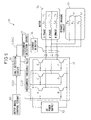
- FIG. 1 is a block diagram schematically showing the configuration of a motor drive apparatus according to a first embodiment of the present invention.
- a DC power supply 2 converts AC power, supplied from an AC power supply not shown, into DC power.
- the DC power from the DC power supply 2 is supplied to a synchronous motor (hereinafter referred to as the motor) 4 via a power transistor unit 3 comprising power transistors A to F.
- a dynamic braking circuit 5 actuates switches S1 and S2, i.e., relay contacts, so that the power is dissipated through resistors Ru, Rv, and Rw in the dynamic braking circuit 5.
- a motor drive control circuit 10 outputs a dynamic braking circuit control signal SIG1, in response to which a fault detection circuit 11 generates a power transistor control signal SIG2 for controlling the driving/stopping of the motor 4 and supplies it to the power transistors A to F in the power transistor unit 3.
- a current detector 6 detects current flowing from the power transistor unit 3 to the motor 4, converts the current value from analog to digital, and supplies the resulting current signal SIG10 to the fault detection circuit 11.
- the fault detection circuit 11 receives the dynamic braking circuit control signal SIG1 from the motor drive control circuit 10 and the current signal SIG10 from the current detector 6, and detects from these signals a fault occurring in the dynamic braking circuit 5 (such as a contact welding defect or an electrically inoperable contact, breakage of a resistor, or disconnection of a connecting cable).
- a fault occurring in the dynamic braking circuit 5 such as a contact welding defect or an electrically inoperable contact, breakage of a resistor, or disconnection of a connecting cable.
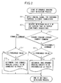
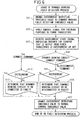
- FIG. 2 is a flowchart illustrating a fault detection process for the dynamic braking circuit in the motor drive apparatus 1 shown in FIG. 1 .
- the process is executed by the fault detection circuit 11 comprising a conventional computer, that is, a CPU, an input/output interface, a RAM, a ROM, a disk, etc.
- step 201 the power transistor control signal SIG2 for checking purposes is applied to the power transistors A to F for a predetermined length of time ⁇ t.
- the predetermined length of time ⁇ t during which the voltage is applied from the DC power supply 2 to the dynamic braking circuit 5 is chosen so that the transient current that flows through the motor windings after the power transistors are turned on does not exceed the current that flows through the dynamic braking resistors.
- step 202 the current that is output from the power transistors A to F is detected by the current detector 6, and the analog-to-digital converted current signal SIG10 (current value I) is received.
- step 203 the dynamic braking circuit 5 checks whether the dynamic braking circuit control signal SIG1 output from the motor drive control circuit 10 is indicating a connect command or not; if the result of the check is YES, the process proceeds to step 214, but if the result of the check is NO, the process proceeds to step 204.
- step 204 the current value I received in step 202 is compared with a threshold value TH, and if I ⁇ TH, the process proceeds to step 205, but if I ⁇ TH, the routine is terminated.
- the threshold value TH may be changed according to the resistance values Ru, Rv, and Rw of the dynamic braking circuit 5 or the inductances Lu, Lv, and Lw of the motor.
- an overcurrent detection circuit (not shown) incorporated in the motor drive control circuit 10 may be used as the current detector 6, and the threshold value may be set so as to serve as an overcurrent detection level when checking the dynamic braking unit 5 for faults.
- step 205 it is determined that the dynamic braking circuit 5 is faulty, and a message "DYNAMIC BRAKING CIRCUIT TO BE DISCONNECTED IS FAULTY" is produced using a display or a printer not shown in FIG. 1 .
- step 214 the current value I received in step 202 is compared with the threshold value TH, and if I > TH, the process proceeds to step 215, but if I ⁇ TH, the routine is terminated.
- step 215 it is determined that the dynamic braking circuit 5 is faulty, and a message "DYNAMIC BRAKING CIRCUIT TO BE CONNECTED IS FAULTY" is produced using a display or a printer not shown in FIG. 1 .
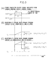
- FIGS. 3A to 3C are time charts showing a first specific example of the pattern of the dynamic braking circuit control signal and the resulting current (when there is no current detection delay) in the motor drive apparatus shown in FIG. 1 :
- FIG. 3A shows the power transistor ON/OFF signal output from the fault detection circuit
- FIG. 3B shows the waveform of the current when the dynamic braking circuit is not connected
- FIG. 3C shows the waveform of the current when the dynamic braking circuit is connected.
- the abscissa represents the time
- the ordinate in FIG. 3A represents the ON/OFF state
- the ordinate in FIGS. 3B and 3C represents the waveform of the current.
- the dynamic braking circuit 5 is connected to the motor power line, and the energy from the motor 4 is dissipated through the resistors Ru, Rv, and Rw in the dynamic braking circuit 5, thereby reducing the stopping distance of the motor.
- the dynamic braking circuit 5 is disconnected from the power transistor unit 3 which is a motor drive circuit, and only the motor 5 is connected to the motor driving power transistor unit 3.
- the contacts for connecting the dynamic braking circuit 5 to the motor power line remain closed due to welding defects, and the dynamic braking circuit 5 is not disconnected from the motor power line when driving the motor 4, the currents Iu, Iv, and Iw for driving the motor 4 flow into the dynamic braking circuit 5, resulting in an inability to perform desired current control or in overheating the resistors in the dynamic braking circuit 5 or generating an overcurrent alarm.
- the motor drive apparatus 1 provided by the present invention is equipped with a capability to apply a dynamic braking checking control signal SIG2 before driving the motor 4 and thereby verify that the dynamic braking circuit 5 is disconnected or connected properly.
- the DC power supply 2 for driving the motor 4 is obtained by rectifying the input AC power, and the voltage from the DC power supply 2 is applied via the power transistors A to F to the motor windings Lu, Lv, and Lw for a suitable length of time for the respective phases U, V, and W of the motor 4, and the currents Iu, Iv, and Iw flowing from the power transistors A to F to the resistors ru, rv, and rw of the respective windings of the motor 4 are detected by the current detector 6 to check the dynamic braking circuit 5 for any fault.
- Equation 1 can be approximated by Equation 2 shown below.
- the first term Vdc/L*t represents the current I (Iu, Iv, Iw) that flows into the windings Lu, Lv, and Lw of the motor 4, and the second term Vdc/R represents the current I (Iu, Iv, Iw) that flows into the dynamic braking circuit 5.
- the first characteristic here is that the current I (Iu, Iv, Iw) that flows when the dynamic braking circuit 5 is disconnected is different by an amount equal to Vdc/R from that when the dynamic braking circuit 5 is connected.
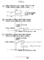
- FIGS. 4A to 4C are time charts showing a second specific example of the pattern of the dynamic braking circuit control signal and the resulting current (when there is current detection delay) in the motor drive apparatus shown in FIG. 1 :
- FIG. 4A shows the power transistor ON/OFF signal output from the fault detection circuit
- FIG. 4B shows the waveform of the current when the dynamic braking circuit is not connected
- FIG. 4C shows the waveform of the current when the dynamic braking circuit is connected.
- the abscissa represents the time
- the ordinate in FIG. 4A represents the ON/OFF state
- the ordinate in FIGS. 4B and 4C represents the waveform of the current.
- the current I (the first term) (Iu, Iv, Iw) that flows into the windings Lu, Lv, and Lw of the motor 4 has a large inductive component, and hence the second characteristic that it takes time to rise after the power transistors A to F are turned on.
- the predetermined length of time ⁇ t during which the voltage is applied from the DC power supply 2 is set longer than the current detection delay time ⁇ that occurs when the current detector 5 detects the current.
- the current I (Iu, Iv, Iw) flowing from the power transistors A to F is detected immediately after ( ⁇ t seconds after) switching the power transistors A to F, if, despite the presence of a command for connecting the dynamic braking circuit 5 to the windings Lu, Lv, and Lw of the motor 4, the current I (Iu, Iv, Iw) flowing from the power transistors A to F is smaller than a threshold value which is set as a current value smaller than Vdc/R but larger than Vdc/L* ⁇ t, it is determined that a fault has occurred such as an electrically inoperable contact in the switches S1 and S2 functioning as relay contacts for connecting the dynamic braking circuit 5, breakage of a resistor in the dynamic braking circuit 5, or disconnection of a connecting cable to the motor power line.
- An overcurrent detection circuit (not shown) originally provided in the motor drive control circuit 10 may be used to detect the current value.
- an overcurrent detection circuit 57 such as shown in FIG. 5 described below is used, it is also possible to use the threshold value by switching between the threshold value for checking the dynamic braking circuit 5 (the overcurrent detection level) and the normal (motor driving) overcurrent detection level.
- FIG. 5 is a block diagram schematically showing the configuration of a motor drive apparatus according to a second embodiment of the present invention.
- the DC power output from a DC power supply 52 is supplied to a motor 54 via a power transistor unit 53 comprising power transistors A to F.
- a dynamic braking circuit 55 actuates switches S1 and S2, i.e., relay contacts, so that the power is dissipated through resistors Ru, Rv, and Rw in the dynamic braking circuit 55.
- a motor drive control circuit 60 outputs a dynamic braking circuit control signal SIG1, in response to which a fault detection circuit 61 generates a power transistor control signal SIG2 for controlling the driving/stopping of the motor 4 and supplies it to the power transistors A to F in the power transistor unit 53.
- a current detector 56 detects current flowing from the power transistor unit 53 to the motor 54.
- An overcurrent detection circuit 57 compares the current value, detected and analog-to-digital converted by the current detector 56, with the overcurrent threshold value supplied to the overcurrent detection circuit 57, and supplies the resulting overcurrent state signal SIG50 to the fault detection circuit 61.
- the fault detection circuit 61 receives the dynamic braking circuit control signal SIG1 from the motor drive control circuit 60 and the overcurrent state signal SIG50 from the overcurrent detection circuit 57, and detects from these signals a fault occurring in the dynamic braking circuit 55 (such as a contact welding defect or an electrically inoperable contact, breakage of a resistor, or disconnection of a connecting cable).
- a fault occurring in the dynamic braking circuit 55 such as a contact welding defect or an electrically inoperable contact, breakage of a resistor, or disconnection of a connecting cable.
- FIG. 6 is a flowchart illustrating a fault detection process for the dynamic braking circuit in the motor drive apparatus shown in FIG. 5 .
- the process is executed by the fault detection circuit 61 comprising a conventional computer, that is, a CPU, an input/output interface, a RAM, a ROM, a disk, etc.
- step 601 the overcurrent detection threshold value is changed from the normal control threshold value THNM to the dynamic braking fault detection threshold value THTM.
- step 602 the power transistor control signal SIG2 for checking purposes is applied to the power transistors A to F for a predetermined length of time ⁇ t.
- the predetermined length of time ⁇ t is set sfficiently longer than the current detection delay time ⁇ ( ⁇ t » ⁇ ).
- step 603 the current that is output from the power transistors A to F is detected and analog-to-digital converted by the current detector 56, and the overcurrent state signal SIG50 output from the overcurrent detection circuit 57 in response to the analog-to-digital converted current value I is received.
- the overcurrent detecting circuit 57 compares the current value I with the test mode threshold value THTM and, if I ⁇ THTM, it is determined that the current is not an overcurrent, and a level "0" is output; on the other hand, if I ⁇ THTM, it is determined that the current is an overcurrent, and a level "1" is output.
- step 604 the dynamic braking circuit 55 checks whether the dynamic braking circuit control signal SIG1 output from the motor drive control circuit 60 is indicating a connect command; if the result of the check is YES, the process proceeds to step 615, but if the result of the check is NO, the process proceeds to step 605.
- step 605 if the overcurrent state signal SIG50 received in step 603 is at level "0,” the process proceeds to step 607, but if it is at level "1,” the process proceeds to step 606.
- step 606 it is determined that the dynamic braking circuit 55 is faulty, and a message "DYNAMIC BRAKING CIRCUIT TO BE DISCONNECTED IS FAULTY" is produced using a display or a printer not shown in FIG. 5 .
- step 607 the overcurrent detection threshold value is changed from the dynamic braking fault detection threshold value THTM to the normal control threshold value THNM, and then the routine is terminated.
- step 615 if the overcurrent state signal SIG10 received in step 603 is at level "0," the process proceeds to step 616, but if it is at level "1,” the process proceeds to step 607.
- step 616 it is determined that the dynamic braking circuit 55 is faulty, and a message "DYNAMIC BRAKING CIRCUIT TO BE CONNECTED IS FAULTY" is produced using a display or a printer not shown in FIG. 5 .
Landscapes
- Engineering & Computer Science (AREA)
- Power Engineering (AREA)
- Stopping Of Electric Motors (AREA)
- Control Of Ac Motors In General (AREA)
Applications Claiming Priority (1)
| Application Number | Priority Date | Filing Date | Title |
|---|---|---|---|
| JP2008001916A JP4361116B2 (ja) | 2008-01-09 | 2008-01-09 | ダイナミックブレーキ回路故障検出機能を備えたモータ駆動装置 |
Publications (3)
| Publication Number | Publication Date |
|---|---|
| EP2079159A2 true EP2079159A2 (de) | 2009-07-15 |
| EP2079159A3 EP2079159A3 (de) | 2015-06-24 |
| EP2079159B1 EP2079159B1 (de) | 2017-07-05 |
Family
ID=40210524
Family Applications (1)
| Application Number | Title | Priority Date | Filing Date |
|---|---|---|---|
| EP08020765.7A Ceased EP2079159B1 (de) | 2008-01-09 | 2008-11-28 | Mit dynamischer Bremskreisfehlererkennungsfähigkeit ausgestattete Motorantriebsvorrichtung |
Country Status (4)
| Country | Link |
|---|---|
| US (1) | US8054015B2 (de) |
| EP (1) | EP2079159B1 (de) |
| JP (1) | JP4361116B2 (de) |
| CN (1) | CN101483402B (de) |
Cited By (1)
| Publication number | Priority date | Publication date | Assignee | Title |
|---|---|---|---|---|
| WO2013113051A2 (de) | 2012-02-03 | 2013-08-08 | Fts Computertechnik Gmbh | Verfahren und vorrichtung zur überwachung der kurzschluss-schalteinrichtung eines drehstrommotors |
Families Citing this family (32)
| Publication number | Priority date | Publication date | Assignee | Title |
|---|---|---|---|---|
| JP2009142115A (ja) * | 2007-12-10 | 2009-06-25 | Yaskawa Electric Corp | モータ制御装置とその故障検出方法 |
| DE102009046617A1 (de) * | 2009-11-11 | 2011-05-19 | Zf Friedrichshafen Ag | Wechselrichter |
| EP2372860A1 (de) * | 2010-03-30 | 2011-10-05 | Converteam Technology Ltd | Schutzschaltungen und Verfahren für elektrische Maschinen |
| US8878468B2 (en) * | 2011-04-29 | 2014-11-04 | Pratt & Whitney Canada Corp. | Electric machine assembly with fail-safe arrangement |
| KR20130019911A (ko) * | 2011-08-18 | 2013-02-27 | 현대모비스 주식회사 | 차량용 제동 시스템에서 모터 권선 코일 이상 검출 장치 및 그 방법 |
| JP5421405B2 (ja) * | 2012-02-28 | 2014-02-19 | ファナック株式会社 | ダイナミックブレーキ制御手段を備えるモータ駆動装置 |
| US9056551B2 (en) * | 2012-09-10 | 2015-06-16 | Caterpillar Global Mining Llc | Braking system contactor control and/or monitoring system and method |
| JP6144900B2 (ja) * | 2012-12-03 | 2017-06-07 | オークマ株式会社 | ダイナミックブレーキ検査機能を備えたインバータ装置 |
| DE102012224188A1 (de) * | 2012-12-21 | 2014-06-26 | Wobben Properties Gmbh | Verfahren zur Steuerung eines Wasserschütz-Antriebs für ein Wasserschütz mit einer elektrischen Maschine, Betriebsschaltung, Wasserschütz-Antrieb und Wasserkraftanlage |
| JP6073147B2 (ja) * | 2013-02-06 | 2017-02-01 | 株式会社日立産機システム | ダイナミックブレーキ回路の検査方法を有したモータ駆動電力変換装置 |
| JP2014190773A (ja) * | 2013-03-26 | 2014-10-06 | Toyota Motor Corp | 過電流検出装置及びそれを備える半導体駆動装置 |
| US9013123B2 (en) * | 2013-04-22 | 2015-04-21 | Rockwell Automation Technologies, Inc. | Self protected dynamic braking |
| JP5980969B2 (ja) | 2015-01-29 | 2016-08-31 | ファナック株式会社 | ダイナミックブレーキ回路故障検出機能を備えたモータ駆動装置 |
| JP6423765B2 (ja) * | 2015-07-31 | 2018-11-14 | ファナック株式会社 | ブレーキの作動及び解除異常を検知する機能を有するブレーキ装置 |
| JP6193937B2 (ja) * | 2015-08-27 | 2017-09-06 | ファナック株式会社 | 分流器の故障を検出する機能を有するモータ駆動装置 |
| JP6356716B2 (ja) * | 2016-02-29 | 2018-07-11 | ファナック株式会社 | トルク指令制限部を有するモータ制御装置 |
| JP6400617B2 (ja) * | 2016-02-29 | 2018-10-03 | ファナック株式会社 | トルク指令制限部を有するモータ制御装置 |
| JP6301511B2 (ja) * | 2017-01-04 | 2018-03-28 | 株式会社日立産機システム | モータシステム |
| DE102017106008B4 (de) * | 2017-03-21 | 2019-07-04 | Schaeffler Technologies AG & Co. KG | Verfahren zur Erkennung eines Kurzschlusses einer Endstufe eines Elektromotors, vorzugsweise eines elektrisch kommutierten Elektromotors |
| CN107086843A (zh) * | 2017-06-30 | 2017-08-22 | 广东美的制冷设备有限公司 | 电机驱动系统和变频空调器 |
| CN111033287B (zh) * | 2017-09-25 | 2022-06-03 | 日本电产株式会社 | 故障诊断方法、马达控制方法、电力转换装置、马达模块以及电动助力转向装置 |
| JP6904201B2 (ja) * | 2017-09-27 | 2021-07-14 | セイコーエプソン株式会社 | ロボット制御装置、ロボット、及びロボットシステム |
| JP6577549B2 (ja) * | 2017-10-12 | 2019-09-18 | ファナック株式会社 | 故障検出機能を有するモータ駆動装置 |
| CN108004973B (zh) * | 2017-12-25 | 2023-11-21 | 深圳市威捷机电股份公司 | 控制停电时能手动起落闸杆的道闸电路 |
| CN109471027B (zh) * | 2018-11-20 | 2021-03-02 | 南京国电南自维美德自动化有限公司 | 一种励磁系统的功率单元自检方法 |
| CN109406997B (zh) * | 2018-11-30 | 2020-11-10 | 北京新能源汽车股份有限公司 | 电机主动短路继电器的测试方法及装置和存储介质 |
| CN109358288A (zh) * | 2018-12-17 | 2019-02-19 | 南京埃斯顿自动化股份有限公司 | 一种伺服动态制动电路的故障检测方法 |
| CN110460272A (zh) * | 2019-09-16 | 2019-11-15 | 江苏科技大学 | 大功率永磁同步电机能量泄放装置及控制方法 |
| CN114047461B (zh) * | 2021-09-07 | 2024-11-12 | 湖南皓天信息科技有限公司 | 一种电压型传感器通路故障检测方法、系统、设备及计算机可读介质 |
| JP7689901B2 (ja) * | 2021-10-22 | 2025-06-09 | 山洋電気株式会社 | モータ制御装置 |
| CN114323378B (zh) * | 2021-12-30 | 2024-01-23 | 中国科学院工程热物理研究所 | 电力测功系统及电力测功的方法 |
| US20250091444A1 (en) * | 2022-04-01 | 2025-03-20 | Mitsubishi Electric Corporation | Drive device and deterioration discrimination method |
Citations (1)
| Publication number | Priority date | Publication date | Assignee | Title |
|---|---|---|---|---|
| JP3383965B2 (ja) | 1994-05-25 | 2003-03-10 | 株式会社安川電機 | サーボ制御装置のdb回路故障検出方法 |
Family Cites Families (10)
| Publication number | Priority date | Publication date | Assignee | Title |
|---|---|---|---|---|
| JPH0697875B2 (ja) * | 1987-05-20 | 1994-11-30 | 日本オ−チス・エレベ−タ株式会社 | エレベ−タ駆動用インバ−タ |
| JP3438748B2 (ja) | 1994-07-14 | 2003-08-18 | 株式会社安川電機 | サーボモータ制御装置の発電制動異常検出方法 |
| JP4526612B2 (ja) | 1999-02-25 | 2010-08-18 | 三菱電機株式会社 | サーボ装置 |
| JP4735918B2 (ja) | 2001-06-20 | 2011-07-27 | 株式会社安川電機 | モータ制御装置 |
| EP2113999A3 (de) * | 2001-09-25 | 2010-01-06 | Daikin Industries, Ltd. | Phasenstromerkennungsvorrichtung |
| KR100488523B1 (ko) * | 2003-02-14 | 2005-05-11 | 삼성전자주식회사 | 모터제어장치 및 그 제어방법 |
| US20040232864A1 (en) * | 2003-05-23 | 2004-11-25 | Hideki Sunaga | Apparatus for controlling motor |
| JP3851617B2 (ja) * | 2003-05-27 | 2006-11-29 | ファナック株式会社 | モータ駆動装置 |
| JP2007174729A (ja) * | 2005-12-19 | 2007-07-05 | Yaskawa Electric Corp | 電動機駆動装置とダイナミックブレーキ回路保護方法 |
| US7479756B2 (en) * | 2006-06-19 | 2009-01-20 | Rockwell Automation Technologies, Inc. | System and method for protecting a motor drive unit from motor back EMF under fault conditions |
-
2008
- 2008-01-09 JP JP2008001916A patent/JP4361116B2/ja not_active Expired - Fee Related
- 2008-11-28 US US12/324,972 patent/US8054015B2/en active Active
- 2008-11-28 EP EP08020765.7A patent/EP2079159B1/de not_active Ceased
- 2008-12-08 CN CN200810184613XA patent/CN101483402B/zh not_active Expired - Fee Related
Patent Citations (1)
| Publication number | Priority date | Publication date | Assignee | Title |
|---|---|---|---|---|
| JP3383965B2 (ja) | 1994-05-25 | 2003-03-10 | 株式会社安川電機 | サーボ制御装置のdb回路故障検出方法 |
Cited By (5)
| Publication number | Priority date | Publication date | Assignee | Title |
|---|---|---|---|---|
| WO2013113051A2 (de) | 2012-02-03 | 2013-08-08 | Fts Computertechnik Gmbh | Verfahren und vorrichtung zur überwachung der kurzschluss-schalteinrichtung eines drehstrommotors |
| AT512477A1 (de) * | 2012-02-03 | 2013-08-15 | Fts Computertechnik Gmbh | Verfahren und vorrichtung zur überwachung der kurzschluss-schalteinrichtung eines drehstrommotors |
| WO2013113051A3 (de) * | 2012-02-03 | 2014-02-20 | Fts Computertechnik Gmbh | Verfahren und vorrichtung zur überwachung der kurzschluss-schalteinrichtung eines drehstrommotors |
| US9329242B2 (en) | 2012-02-03 | 2016-05-03 | Fts Computertechnik Gmbh | Method and apparatus for monitoring the short-circuiting switching device of a three-phase motor |
| AT512477B1 (de) * | 2012-02-03 | 2016-09-15 | Fts Computertechnik Gmbh | Verfahren und vorrichtung zur überwachung der kurzschluss-schalteinrichtung eines drehstrommotors |
Also Published As
| Publication number | Publication date |
|---|---|
| EP2079159B1 (de) | 2017-07-05 |
| JP2009165296A (ja) | 2009-07-23 |
| US8054015B2 (en) | 2011-11-08 |
| JP4361116B2 (ja) | 2009-11-11 |
| CN101483402B (zh) | 2013-02-13 |
| CN101483402A (zh) | 2009-07-15 |
| US20090174349A1 (en) | 2009-07-09 |
| EP2079159A3 (de) | 2015-06-24 |
Similar Documents
| Publication | Publication Date | Title |
|---|---|---|
| EP2079159B1 (de) | Mit dynamischer Bremskreisfehlererkennungsfähigkeit ausgestattete Motorantriebsvorrichtung | |
| US9647581B2 (en) | Motor drive having function of detecting failure in dynamic braking circuit | |
| US20190113576A1 (en) | Motor drive device having failure detection function | |
| CN103941114B (zh) | 车用永磁同步电机系统功率模块及电流传感器的自检方法 | |
| JP5943484B2 (ja) | 直流電源使用時に生ずるアーク放電防止システム | |
| DE102015011507B4 (de) | Elektromotorantrieb mit Funktion zum Detektieren einer Verschweißung eines elektromagnetischen Schalters | |
| US9899954B2 (en) | Motor drive apparatus having function of detecting failure of electric shunt | |
| KR101997834B1 (ko) | 모터 고장 진단 장치 및 방법 | |
| JP2006320176A (ja) | インバータの診断方法及び装置 | |
| CN102301253A (zh) | 用于运行无刷电动机的方法 | |
| JP2009229291A (ja) | Srモータ駆動装置 | |
| KR20190106181A (ko) | 과전류 발생시 모터 구동 전원을 차단하는 eps 제어 장치 및 방법 | |
| KR20160039247A (ko) | 전자 정류식 전기 모터에서 결함 결정 방법 | |
| JP2000013902A (ja) | 電気自動車の交流側漏電検知装置 | |
| JP2001086762A (ja) | 電源装置 | |
| JP7517171B2 (ja) | 異常検出装置、負荷駆動装置、異常検出方法およびプログラム | |
| JP2018152931A (ja) | 鉄道用の車両制御装置及び方法 | |
| CN117940303A (zh) | 用于运行电驱动系统的方法、计算机程序产品、数据载体和电驱动系统 | |
| US11579207B2 (en) | Circuit for checking an electrical wire connected to a digital input of an actuator | |
| KR102799269B1 (ko) | 차량의 인버터용 고장 진단 장치 및 방법 | |
| KR102477497B1 (ko) | 차량 제어기의 단락 고장 검출 방법 | |
| KR20210074013A (ko) | 과전류 감지 회로 및 그 방법 | |
| US20250052802A1 (en) | Supply circuit having a computer device for diagnosing a connecting circuit, in particular for power electronics in a vehicle, and method for operating a supply circuit having a computer device for diagnosing a connecting circuit | |
| JP2004247367A (ja) | リニアソレノイド駆動装置 | |
| JP2026058428A (ja) | 電源制御回路 |
Legal Events
| Date | Code | Title | Description |
|---|---|---|---|
| PUAI | Public reference made under article 153(3) epc to a published international application that has entered the european phase |
Free format text: ORIGINAL CODE: 0009012 |
|
| AK | Designated contracting states |
Kind code of ref document: A2 Designated state(s): AT BE BG CH CY CZ DE DK EE ES FI FR GB GR HR HU IE IS IT LI LT LU LV MC MT NL NO PL PT RO SE SI SK TR |
|
| AX | Request for extension of the european patent |
Extension state: AL BA MK RS |
|
| RAP1 | Party data changed (applicant data changed or rights of an application transferred) |
Owner name: FANUC CORPORATION |
|
| PUAL | Search report despatched |
Free format text: ORIGINAL CODE: 0009013 |
|
| AK | Designated contracting states |
Kind code of ref document: A3 Designated state(s): AT BE BG CH CY CZ DE DK EE ES FI FR GB GR HR HU IE IS IT LI LT LU LV MC MT NL NO PL PT RO SE SI SK TR |
|
| AX | Request for extension of the european patent |
Extension state: AL BA MK RS |
|
| RIC1 | Information provided on ipc code assigned before grant |
Ipc: G01R 31/02 20060101ALN20150515BHEP Ipc: H02P 3/18 20060101AFI20150515BHEP |
|
| 17P | Request for examination filed |
Effective date: 20151223 |
|
| AKX | Designation fees paid |
Designated state(s): DE |
|
| AXX | Extension fees paid |
Extension state: AL Extension state: RS Extension state: BA Extension state: MK |
|
| 17Q | First examination report despatched |
Effective date: 20160602 |
|
| RIC1 | Information provided on ipc code assigned before grant |
Ipc: G01R 31/02 20060101ALN20161215BHEP Ipc: H02P 3/18 20060101AFI20161215BHEP |
|
| GRAP | Despatch of communication of intention to grant a patent |
Free format text: ORIGINAL CODE: EPIDOSNIGR1 |
|
| INTG | Intention to grant announced |
Effective date: 20170126 |
|
| GRAS | Grant fee paid |
Free format text: ORIGINAL CODE: EPIDOSNIGR3 |
|
| GRAA | (expected) grant |
Free format text: ORIGINAL CODE: 0009210 |
|
| AK | Designated contracting states |
Kind code of ref document: B1 Designated state(s): DE |
|
| REG | Reference to a national code |
Ref country code: DE Ref legal event code: R096 Ref document number: 602008050936 Country of ref document: DE |
|
| REG | Reference to a national code |
Ref country code: DE Ref legal event code: R097 Ref document number: 602008050936 Country of ref document: DE |
|
| PLBE | No opposition filed within time limit |
Free format text: ORIGINAL CODE: 0009261 |
|
| STAA | Information on the status of an ep patent application or granted ep patent |
Free format text: STATUS: NO OPPOSITION FILED WITHIN TIME LIMIT |
|
| 26N | No opposition filed |
Effective date: 20180406 |
|
| PGFP | Annual fee paid to national office [announced via postgrant information from national office to epo] |
Ref country code: DE Payment date: 20231003 Year of fee payment: 16 |
|
| REG | Reference to a national code |
Ref country code: DE Ref legal event code: R119 Ref document number: 602008050936 Country of ref document: DE |
|
| PG25 | Lapsed in a contracting state [announced via postgrant information from national office to epo] |
Ref country code: DE Free format text: LAPSE BECAUSE OF NON-PAYMENT OF DUE FEES Effective date: 20250603 |