EP2079169A2 - Appareil de communication, circuit antiparasite, procédé antibruit, et programme antibruit - Google Patents
Appareil de communication, circuit antiparasite, procédé antibruit, et programme antibruit Download PDFInfo
- Publication number
- EP2079169A2 EP2079169A2 EP08165342A EP08165342A EP2079169A2 EP 2079169 A2 EP2079169 A2 EP 2079169A2 EP 08165342 A EP08165342 A EP 08165342A EP 08165342 A EP08165342 A EP 08165342A EP 2079169 A2 EP2079169 A2 EP 2079169A2
- Authority
- EP
- European Patent Office
- Prior art keywords
- reception
- noise
- parameters
- communication
- signal
- Prior art date
- Legal status (The legal status is an assumption and is not a legal conclusion. Google has not performed a legal analysis and makes no representation as to the accuracy of the status listed.)
- Granted
Links
Images





Classifications
-
- H—ELECTRICITY
- H04—ELECTRIC COMMUNICATION TECHNIQUE
- H04B—TRANSMISSION
- H04B1/00—Details of transmission systems, not covered by a single one of groups H04B3/00 - H04B13/00; Details of transmission systems not characterised by the medium used for transmission
- H04B1/06—Receivers
- H04B1/10—Means associated with receiver for limiting or suppressing noise or interference
- H04B1/12—Neutralising, balancing, or compensation arrangements
- H04B1/123—Neutralising, balancing, or compensation arrangements using adaptive balancing or compensation means
- H04B1/126—Neutralising, balancing, or compensation arrangements using adaptive balancing or compensation means having multiple inputs, e.g. auxiliary antenna for receiving interfering signal
-
- H—ELECTRICITY
- H04—ELECTRIC COMMUNICATION TECHNIQUE
- H04B—TRANSMISSION
- H04B1/00—Details of transmission systems, not covered by a single one of groups H04B3/00 - H04B13/00; Details of transmission systems not characterised by the medium used for transmission
- H04B1/06—Receivers
- H04B1/10—Means associated with receiver for limiting or suppressing noise or interference
- H04B1/109—Means associated with receiver for limiting or suppressing noise or interference by improving strong signal performance of the receiver when strong unwanted signals are present at the receiver input
-
- H—ELECTRICITY
- H04—ELECTRIC COMMUNICATION TECHNIQUE
- H04B—TRANSMISSION
- H04B1/00—Details of transmission systems, not covered by a single one of groups H04B3/00 - H04B13/00; Details of transmission systems not characterised by the medium used for transmission
- H04B1/69—Spread spectrum techniques
- H04B1/707—Spread spectrum techniques using direct sequence modulation
Definitions
- the present invention relates to a communication apparatus that starts communication after scanning a plurality of reception channels and cancels a noise signal caused by a radio wave noise source from a reception signal received in the communication, a noise canceller, a noise canceling method, and a noise canceling program for the communication apparatus.
- wireless interfaces such as wideband code divided multiple access (W-CDMA), wireless local area network (WLAN), and 1 seg
- W-CDMA wideband code divided multiple access
- WLAN wireless local area network
- 1 seg radio wave noise from the inside of main bodies of the apparatuses intrudes into antennas of wireless modules. This causes deterioration in a transmission band and interrupts communication.
- I and Q signals are combined and anti-phase noise is added to cancel radio wave noise.
- the I and Q signals are combined while being adapted to optimize communication quality data (e.g., bit error rate (BER)) output from the module to cancel radio wave noise.
- BER bit error rate
- Japanese Patent Application Laid-open No. H2-233026 discloses a technology for canceling noise according to a reception channel. Specifically, to optimize an image quality of a received image for each of reception channels, a television receiver determines in advance whether a noise reducing circuit should be activated or inactivated for each of the reception channels and controls the noise reducing circuit according to a tuned-in reception channel.
- the technology for adding, in an anti-phase, radio wave noise to a reception signal to thereby cancel the radio wave noise has drawbacks.
- W-CDMA and worldwide interoperability for microwave access WiMAX
- WiMAX worldwide interoperability for microwave access
- an image quality of a received image is merely optimized according to a reception channel.
- a reception signal attenuates and a noise signal becomes relatively excessive in a location away from a base station, the reception signal from the base station cannot be received and communication is not started.
- a communication apparatus starts communication after scanning a plurality of reception channels and cancels a noise signal caused by a radio wave noise source from a reception signal received in the communication
- the communication apparatus includes a parameter storing unit that stores parameters for noise cancellation determined in advance for each of the reception channels in a parameter table in association with the reception channels, a parameter readout unit that reads out parameters for noise cancellation corresponding to a reception channel on which reception is about to be started from the parameter table, and a noise canceling unit that cancels a noise signal from the reception signal using the parameters for noise cancellation read out by the parameter readout unit.
- a noise canceller starts communication after scanning a plurality of reception channels and cancels a noise signal caused by a radio wave noise source from a reception signal received in the communication, and includes a parameter storing unit that stores parameters for noise cancellation determined in advance for each of the reception channels in a parameter table in association with the reception channels, a parameter readout unit that reads out parameters for noise cancellation corresponding to a reception channel on which reception is about to be started from the parameter table, and a noise canceling unit that cancels a noise signal from the reception signal using the parameters for noise cancellation read out by the parameter readout unit.
- a noise cancelling method starts communication after scanning a plurality of reception channels and cancels a noise signal caused by a radio wave noise source from a reception signal received in the communication, and includes storing parameters for noise cancellation determined in advance for each of the reception channels in a parameter table in association with the reception channels, reading out parameters for noise cancellation corresponding to a reception channel on which reception is about to be started from the parameter table, and cancelling a noise signal from the reception signal using the parameters for noise cancellation read out at the reading out.
- a computer-readable recording medium stores therein a computer program for starting communication after scanning a plurality of reception channels and cancelling a noise signal caused by a radio wave noise source from a reception signal received in the communication, the computer program causes a computer to execute storing parameters for noise cancellation determined in advance for each of the reception channels in a parameter table in association with the reception channels, reading out parameters for noise cancellation corresponding to a reception channel on which reception is about to be started from the parameter table, and cancelling a noise signal from the reception signal using the parameters for noise cancellation read out at the reading out.
- Fig. 1 is a diagram for explaining an overview and characteristics of a communication apparatus according to a first embodiment of the present invention.
- the communication apparatus is applied to a cellular phone or a notebook personal computer mounted with a wireless interface such as W-CDMA, WiMAX, WLAN, or 1 seg.
- a communication apparatus 10 starts communication after scanning a plurality of reception channels and cancels a noise signal caused by a radio wave noise source from a reception signal received in the communication.
- the communication apparatus 10 has a main characteristic in scanning the reception channels and starting communication with the noise signal optimally cancelled.
- the communication apparatus 10 includes an I and Q digital values table 12 that stores values of I and Q, which are parameters for noise cancellation determined in advance, for each of reception channels (the I and Q digital values table 12 are explained in detail later with reference to Fig. 3 ).
- the communication apparatus 10 reads out parameters for noise cancellation corresponding to a reception channel from the I and Q digital values table 12 (see (1) in Fig. 1 ). Specifically, a phase and amplitude controller 15 of the communication apparatus 10 receives reception channel information (see Fig. 1 ) that indicates a reception channel on which reception is about to be started from a W-CDMA reception module 14. The phase and amplitude controller 15 reads out values of I and Q corresponding to the reception channel from the I and Q digital values table 12 and notifies a phase and amplitude adjusting integrated circuit (IC) 13 of the values.
- IC integrated circuit
- the communication apparatus 10 cancels a noise signal from a reception signal using the read-out parameters for noise cancellation (see (2) in Fig. 1 ).
- the phase and amplitude adjusting IC 13 of the communication apparatus 10 picks up a noise signal from a noise source (e.g., a large scale integration (LSI)) 17.
- the phase and amplitude adjusting IC 13 adjusts the phase and the amplitude of the noise signal and generates a signal using the values of I and Q notified by the phase and amplitude controller 15.
- the phase and amplitude adjusting IC 13 adds, in an anti-phase, the generated signal to the reception signal received by a communication antenna 11 and cancels noise from the reception signal.
- the communication apparatus 10 cancels the noise signal from the reception signal using the parameters for noise cancellation optimized for each of the channels in advance. Therefore, as indicated by the main characteristic described above, even when the reception signal attenuates and the noise signal becomes relatively excessive in a location away from a base station, the noise signal is optimally cancelled. Therefore, it is possible to scan the reception channels and start communication.
- Fig. 2 is a block diagram of a configuration of the communication apparatus 10 according to the first embodiment.
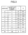
- Fig. 3 is a diagram for explaining an example of the I and Q digital values table 12.
- Fig. 4 is a diagram for explaining cancellation of noise.
- the communication apparatus 10 includes the communication antenna 11, the I and Q digital values table 12, the phase and amplitude adjusting IC 13, the W-CDMA reception module 14, the phase and amplitude controller 15, digital to analog converters (DACs) 16a and 16b, and the LSI 17.
- the communication antenna 11 the I and Q digital values table 12
- the phase and amplitude adjusting IC 13 the W-CDMA reception module 14
- the phase and amplitude controller 15 digital to analog converters (DACs) 16a and 16b
- LSI 17 digital to analog converters
- the communication antenna 11 receives a radio wave, which is transmitted from the base station, as a reception signal using a predetermined channel.
- the communication antenna 11 receives a noise signal radiated by the LSI 17, which is a noise source.
- the DACs 16a and 16b convert values of I and Q, which are received from the phase and amplitude controller 15, from a digital signal into an analog signal and outputs the analog signal to the phase and amplitude adjusting IC 13.
- the I and Q digital values table 12 stores values of I and Q, which are parameters for noise cancellation determined in advance for each of reception channels. For example, as shown in Fig. 3 , the I and Q digital values table 12 stores an "address" for uniquely identifying a reception channel number, a "reception channel number” that indicates a number of a reception channel, and values of the parameters for noise cancellation "I" and "Q" in association with one another.
- I and Q digital values table 12 optimum values of "I” and "Q" are set for each of the reception channels in advance. For example, values of I and Q can be set to optimize a bit error rate (BER) even when a simulated base station is used in an anechoic chamber. Alternatively, values of I and Q can be set to optimize noise cancellation in the respective reception channels while manually changing the values of I and Q.
- BER bit error rate
- the phase and amplitude controller 15 reads out parameters for noise cancellation corresponding to a reception channel from the I and Q digital values table 12. Specifically, when the phase and amplitude controller 15 reads out reception channel information, which indicates a reception channel on which reception is about to be started, from the W-CDMA reception module 14, the phase and amplitude controller 15 reads out values of I and Q corresponding to the reception channel from the I and Q digital values table 12 and notifies the phase and amplitude adjusting IC 13 of the values via the DACs 16a and 16b.
- the phase and amplitude adjusting IC 13 cancels a noise signal from a reception signal using the read-out parameters for noise cancellation. Specifically, the phase and amplitude adjusting IC 13 picks up a noise signal from the LSI 17. The phase and amplitude adjusting IC 13 adjusts the phase and the amplitude of the noise signal and generates a signal using the values of I and Q notified by the phase and amplitude controller 15. Thereafter, the phase and amplitude adjusting IC 13 adds, in an anti-phase, the generated signal to the reception signal received by the communication antenna 11 and cancels noise from the reception signal.
- the W-CDMA reception module 14 scans the respective reception channels at high speed, searches for a base station with which the communication apparatus 10 can communicate, and receives a reception signal from the base station via the communication antenna 11. Specifically, the W-CDMA reception module 14 transmits reception channel information, which indicates a reception channel on which reception is about to be started, to the phase and amplitude controller 15 and receives the reception signal from which noise has been cancelled by the phase and amplitude adjusting IC 13.
- the communication apparatus 10 reads out, from the I and Q digital values table 12, values of I and Q (e.g., I "-63” and Q "1021") corresponding to a reception channel on which reception is about to be started (e.g., a reception channel "CH1").
- the communication apparatus 10 cancels noise using the values of I and Q and scans the reception channel to determine whether the reception channel is a usable reception channel.
- the communication apparatus 10 starts communication using the reception channel.
- the communication apparatus 10 cancels noise using values of I and Q (e.g., I "-127” and Q "1015") corresponding to the next reception channel (e.g., a reception channel "CH2”) and scans the reception channel to determine whether the reception channel is a usable reception channel. Thereafter, the communication apparatus 10 scans reception channels "CH1" to "CHn” in the same manner until a usable reception channel is found.
- I and Q e.g., I "-127" and Q "1015"
- Fig. 5 is a flowchart of processing operations of the communication apparatus 10 according to the first embodiment.
- the phase and amplitude controller 15 of the communication apparatus 10 receives a communication start instruction (Yes at step S101).
- the phase and amplitude controller 15 reads, from the W-CDMA reception module 14, the number of a reception channel on which reception is about to be started (step S102).
- the phase and amplitude controller 15 judges whether the reception channel number has changed (when a first reception channel number is read, whether the reception channel number is read) (step S103). When the reception channel number has not changed (or the first reception channel number is not read) as a result of the judgment (No at step S103), the phase and amplitude controller 15 returns to step S102.
- the phase and amplitude controller 15 reads out values of I and Q corresponding to the reception channel number from the I and Q digital values table 12, and outputs the values to the DACs 16a and 16b (step S104).
- the phase and amplitude adjusting IC 13 cancels noise of the reception signal.
- the communication apparatus 10 cancels a noise signal from a reception signal using parameters for noise cancellation optimized for each of channels in advance. Therefore, even when the reception signal attenuates and the noise signal becomes relatively excessive in a location away from a base station, the noise signal is optimally cancelled. Therefore, it is possible to scan reception channels and start communication.
- the optimum values of "I” and “Q” are set for each of the reception channels in advance.
- the present invention is not limited to this. Values of "I” and “Q” set in advance can be changed.
- Fig. 6 is a diagram of an example of an I and Q digital values table included in a communication apparatus according to the second embodiment.
- Fig. 7 is a diagram for explaining noise cancellation processing by the communication apparatus according to the second embodiment.
- Fig. 8 is a flowchart for explaining a processing procedure of the communication apparatus according to the second embodiment.
- the communication apparatus stores values of "I” and "Q" for each of reception channels set in advance.
- the values of "I” and "Q” are rewritten by the phase and amplitude controller 15.
- the phase and amplitude controller 15 of the communication apparatus outputs to the DACs 16a and 16b using communication quality information (e.g., "BER") received from the W-CDMA reception module 14 while changing the values so that the communication quality information is optimized.
- the phase and amplitude controller 15 writes optimized values of "I” and "Q” in sections corresponding to a reception channel number of the table (in the example shown in Fig. 6 , a reception channel number "4").
- Access control processing according to the second embodiment is different from the processing by the communication apparatus 10 according to the first embodiment shown in Fig. 5 in that the values of "I" and "Q" in the I and Q digital values table are rewritten.
- the phase and amplitude controller 15 of the communication apparatus reads out values of I and Q corresponding to a reception channel number from the I and Q digital values table (step S204).
- the phase and amplitude controller 15 outputs the values of I and Q to the DACs 16a and 16b while changing the values to optimize a BER received from the W-CDMA reception module 14 (step S205).
- the phase and amplitude controller 15 writes the optimized values of I and Q in sections corresponding to the reception channel number of the I and Q digital values table (step S206). In scanning a pilot signal of the base station next time, the phase and amplitude controller 15 uses the rewritten values of I and Q.
- values of I and Q which are parameters for noise cancellation, are set in advance for each of reception channels.
- the present invention is not limited to this. Values of I and Q corresponding to a degree of opening of a cover can be set.
- a communication antenna may be provided in a cover section.
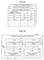
- a communication distance and an angle of the communication antenna change according to a degree of opening of the cover. Therefore, as shown in Fig. 9 , values of I and Q are set in the I and Q digital values table in association with a degree of opening of the cover (an angle of opening of the cover).
- the components of the devices shown in the figures are functionally conceptual and are not always required to be physically configured as shown in the figures.
- a specific form of distribution and integration of the devices is not limited to that shown in the figures.
- a part or all of the devices can be functionally or physically distributed and integrated in arbitrary units according to various loads and states of use.
- the phase and amplitude adjusting IC 13 and the phase and amplitude controller 15 can be integrated.
- all or an arbitrary part of the processing functions performed by the devices can be realized by a CPU and a program analyzed and executed by the CPU, or can be realized as hardware by a wired logic.
- all or a part of the kinds of processing explained as being automatically performed can be manually performed.
- all or a part of the kinds of processing explained as being manually performed can be automatically performed by a known method.
- the processing procedure, the control procedure, the specific names, and the information including the various data and parameters explained above and shown in the figures can be arbitrarily changed unless specifically noted otherwise.
- the values of the I and Q digital values table 12 can be arbitrarily changed.
- Fig. 10 is a diagram of a computer that executes a noise canceling program.
- a computer 600 as a communication apparatus is configured by connecting a hard disk (HDD) 610, a random access memory (RAM) 620, a read only memory (ROM) 630, and a central processing unit (CPU) 640 through a bus 650.
- HDD hard disk
- RAM random access memory
- ROM read only memory
- CPU central processing unit
- a noise canceling program 631 that exerts the same functions as the communication apparatuses according to the embodiments is stored in the ROM 630 in advance as shown in Fig. 10 .
- the CPU 640 reads out the noise canceling program 631 from the ROM 630 and executes the same. Consequently, as shown in Fig. 10 , the noise canceling program 631 functions as a noise canceling process 641.
- An I and Q digital values table 611 is provided in the HDD 610 as shown in Fig. 10 .
- the I and Q digital values table 611 corresponds to the I and Q digital values table 12 shown in Fig. 2 .
- the CPU 640 registers data in the I and Q digital values table 611 and reads out I and Q digital values data 621 from the I and Q digital values table 611 and stores the same in the RAM 620.
- the CPU 640 executes processing based on the I and Q digital values data 621 stored in the RAM 620.
- the apparatus cancels a noise signal from a reception signal using parameters for noise cancellation optimized for each of channels in advance. Therefore, even when the reception signal attenuates and the noise signal becomes relatively excessive in a location away from a base station, the noise signal is optimally cancelled. Therefore, it is possible to scan reception channels and start communication.
Landscapes
- Engineering & Computer Science (AREA)
- Computer Networks & Wireless Communication (AREA)
- Signal Processing (AREA)
- Noise Elimination (AREA)
- Transceivers (AREA)
Applications Claiming Priority (1)
| Application Number | Priority Date | Filing Date | Title |
|---|---|---|---|
| JP2008004935A JP5311831B2 (ja) | 2008-01-11 | 2008-01-11 | 通信装置、ノイズキャンセラ、ノイズ除去方法およびノイズ除去プログラム |
Publications (3)
| Publication Number | Publication Date |
|---|---|
| EP2079169A2 true EP2079169A2 (fr) | 2009-07-15 |
| EP2079169A3 EP2079169A3 (fr) | 2012-04-04 |
| EP2079169B1 EP2079169B1 (fr) | 2016-11-30 |
Family
ID=40568673
Family Applications (1)
| Application Number | Title | Priority Date | Filing Date |
|---|---|---|---|
| EP08165342.0A Ceased EP2079169B1 (fr) | 2008-01-11 | 2008-09-29 | Appareil de communication, circuit antiparasite, procédé antibruit, et programme antibruit |
Country Status (3)
| Country | Link |
|---|---|
| US (1) | US8428540B2 (fr) |
| EP (1) | EP2079169B1 (fr) |
| JP (1) | JP5311831B2 (fr) |
Families Citing this family (7)
| Publication number | Priority date | Publication date | Assignee | Title |
|---|---|---|---|---|
| US8135372B2 (en) * | 2009-09-08 | 2012-03-13 | Bae Systems Information And Elecronic Systems Integration Inc. | Integrated cancellation circuit for RF converter spurious tones |
| JP5196593B2 (ja) * | 2010-02-18 | 2013-05-15 | パナソニック株式会社 | 無線端末 |
| WO2012008028A1 (fr) * | 2010-07-14 | 2012-01-19 | 富士通株式会社 | Dispositif de commande d'annulation du bruit, programme de commande d'annulation du bruit et procédé de commande d'annulation du bruit |
| JP5686181B2 (ja) * | 2011-03-18 | 2015-03-18 | 富士通株式会社 | ノイズキャンセルパラメータの設定を行う情報処理装置およびノイズキャンセルパラメータ設定プログラム |
| US10152960B2 (en) | 2015-09-22 | 2018-12-11 | Cirrus Logic, Inc. | Systems and methods for distributed adaptive noise cancellation |
| CN109951198B (zh) * | 2017-12-20 | 2022-06-07 | 三星电子株式会社 | 执行选择性噪声滤波的无线通信设备及操作该设备的方法 |
| US12592731B2 (en) * | 2021-03-02 | 2026-03-31 | Sony Group Corporation | Noise canceling apparatus, noise canceling method, and electronic equipment |
Citations (2)
| Publication number | Priority date | Publication date | Assignee | Title |
|---|---|---|---|---|
| JPH02233026A (ja) | 1989-03-07 | 1990-09-14 | Matsushita Electric Ind Co Ltd | テレビジョン受像機 |
| JP2004236171A (ja) | 2003-01-31 | 2004-08-19 | Ntt Docomo Inc | 無線通信端末 |
Family Cites Families (23)
| Publication number | Priority date | Publication date | Assignee | Title |
|---|---|---|---|---|
| US4736455A (en) | 1985-12-23 | 1988-04-05 | Nippon Telegraph And Telephone Corporation | Interference cancellation system |
| EP0371433B1 (fr) | 1988-11-28 | 1994-10-12 | Nec Corporation | Démodulateur à annuleurs d'interférences multiples répondant aux corrélations entre signaux indésirés et signaux d'erreur |
| DE69535621T2 (de) * | 1994-09-02 | 2008-02-07 | Matsushita Electric Industrial Co., Ltd., Kadoma | Erkennungsvorrichtung zur Modulationsgrad |
| JPH08335915A (ja) | 1995-06-08 | 1996-12-17 | Matsushita Electric Ind Co Ltd | 電磁波障害除去方法 |
| JPH1127160A (ja) * | 1997-07-04 | 1999-01-29 | Kokusai Electric Co Ltd | 無線情報端末 |
| EP1069693B1 (fr) * | 1999-07-15 | 2004-10-13 | Mitsubishi Denki Kabushiki Kaisha | Dispositif de réduction de bruit |
| JP3368879B2 (ja) * | 1999-12-22 | 2003-01-20 | 三菱電機株式会社 | マルチパスノイズ除去装置、オーディオ出力装置およびfm受信機 |
| US20020044614A1 (en) * | 2000-09-12 | 2002-04-18 | Molnar Karl James | Methods and systems for reducing interference using co-channel interference mapping |
| US6915112B1 (en) * | 2000-11-12 | 2005-07-05 | Intel Corporation | Active cancellation tuning to reduce a wireless coupled transmit signal |
| FR2825550B1 (fr) * | 2001-05-30 | 2003-09-05 | Mitsubishi Electric Inf Tech | Dispositif et procede de demodulation numerique d'un signal recu par selection d'un filtre et recepteur de communication numerique le comportant |
| US6968171B2 (en) * | 2002-06-04 | 2005-11-22 | Sierra Wireless, Inc. | Adaptive noise reduction system for a wireless receiver |
| JP3776872B2 (ja) | 2002-11-21 | 2006-05-17 | Necインフロンティア株式会社 | ノイズ低減装置及びそれを用いた無線lan基地局装置 |
| JP2004228920A (ja) * | 2003-01-23 | 2004-08-12 | Sony Ericsson Mobilecommunications Japan Inc | 携帯通信端末 |
| JP4214992B2 (ja) * | 2004-12-13 | 2009-01-28 | パナソニック株式会社 | 高周波受信器とこれに用いる集積回路及び、これらを用いた携帯機器、ならびにこれに用いる送信器と、前記高周波受信器および前記携帯機器の製造方法 |
| EP1834321B1 (fr) * | 2004-12-14 | 2014-07-09 | Intersil Americas LLC | Procede et systeme de reduction de l'interference de signaux |
| US7787648B1 (en) * | 2005-08-26 | 2010-08-31 | At&T Mobility Ii Llc | Active cancellation hearing assistance device |
| JP4277848B2 (ja) | 2005-11-21 | 2009-06-10 | トヨタ自動車株式会社 | 車載受信装置 |
| KR100764437B1 (ko) * | 2006-02-17 | 2007-10-05 | 삼성전기주식회사 | 전화신호 제거 회로, 디지털 방송 수신 회로 및 휴대용디지털 방송 수신기 |
| JP4632971B2 (ja) * | 2006-03-03 | 2011-02-16 | Necカシオモバイルコミュニケーションズ株式会社 | 撮像機能を有する端末、および、プログラム |
| US7929933B2 (en) * | 2006-10-23 | 2011-04-19 | Panasonic Corporation | Noise suppression apparatus, FM receiving apparatus and FM receiving apparatus adjustment method |
| JP4941338B2 (ja) * | 2008-02-01 | 2012-05-30 | 富士通株式会社 | 通信装置、ノイズ除去方法及びコンピュータプログラム |
| JP4881913B2 (ja) * | 2008-05-29 | 2012-02-22 | 本田技研工業株式会社 | 能動型騒音制御装置 |
| US8135372B2 (en) * | 2009-09-08 | 2012-03-13 | Bae Systems Information And Elecronic Systems Integration Inc. | Integrated cancellation circuit for RF converter spurious tones |
-
2008
- 2008-01-11 JP JP2008004935A patent/JP5311831B2/ja not_active Expired - Fee Related
- 2008-09-23 US US12/232,755 patent/US8428540B2/en not_active Expired - Fee Related
- 2008-09-29 EP EP08165342.0A patent/EP2079169B1/fr not_active Ceased
Patent Citations (2)
| Publication number | Priority date | Publication date | Assignee | Title |
|---|---|---|---|---|
| JPH02233026A (ja) | 1989-03-07 | 1990-09-14 | Matsushita Electric Ind Co Ltd | テレビジョン受像機 |
| JP2004236171A (ja) | 2003-01-31 | 2004-08-19 | Ntt Docomo Inc | 無線通信端末 |
Also Published As
| Publication number | Publication date |
|---|---|
| EP2079169A3 (fr) | 2012-04-04 |
| JP2009171059A (ja) | 2009-07-30 |
| JP5311831B2 (ja) | 2013-10-09 |
| EP2079169B1 (fr) | 2016-11-30 |
| US20090181632A1 (en) | 2009-07-16 |
| US8428540B2 (en) | 2013-04-23 |
Similar Documents
| Publication | Publication Date | Title |
|---|---|---|
| EP2079169B1 (fr) | Appareil de communication, circuit antiparasite, procédé antibruit, et programme antibruit | |
| US8103235B2 (en) | Communicating apparatus, noise canceling method and memory product | |
| CN101895939B (zh) | 一种通信方法和处理通信信号的系统 | |
| CN105900341B (zh) | 使用rx分集天线的机会主义主动干扰消除的方法和装置 | |
| KR20170115539A (ko) | Gnss 수신기 및 하나 이상의 rat 트랜시버들의 공존을 관리하기 위한 방법 및 장치 | |
| CN102970752A (zh) | 用于多种无线通信技术之间的共存的分组类型欺骗 | |
| US8406274B1 (en) | Scheduled gain control in collocated wireless receivers using forward timed signal strength predictions | |
| GB2389484A (en) | Channel measurement technique for a radio communication terminal | |
| US9632184B2 (en) | Systems and methods for managing the coexistence of a GNSS receiver and a RAT transceiver | |
| JP2018207321A (ja) | キャンセル装置、キャンセル方法、および無線通信装置 | |
| EP2334123B1 (fr) | Procédé de correction de puissance s'adaptant à de multiples bandes passantes de signal | |
| JP2005086448A (ja) | リピータ装置 | |
| US9124323B2 (en) | Interference reduction method | |
| JP2009111630A (ja) | 移動無線端末装置 | |
| KR102380152B1 (ko) | 위성 안테나 빔의 지향 방법 및 장치, 컴퓨터 판독 가능한 기록 매체 및 컴퓨터 프로그램 | |
| US20090042512A1 (en) | Mobile communication system, base station, and inter-cell interference reduction method | |
| US8918058B2 (en) | Wireless communication apparatus and wireless communication method | |
| US12520313B2 (en) | User equipment and communication methods for semi-static DL scheduling | |
| JP4129467B2 (ja) | 移動通信端末、及び電波干渉回避方法 | |
| JP5739964B2 (ja) | アンテナ装置 | |
| JP4786524B2 (ja) | 基地局アンテナのキャリブレーション方法、及び通信基地局 | |
| KR20050090751A (ko) | 지에스엠 이동 단말기의 동적 전송 파워 보정 방법 및이에 적용되는 전송 파워 보정 시스템 | |
| US20210181295A1 (en) | Positioning system, positioning method, and recording medium | |
| JP4841502B2 (ja) | 回り込みキャンセラ回路 | |
| KR20170021167A (ko) | 이동기지국의 셀간 간섭 완화 방법 |
Legal Events
| Date | Code | Title | Description |
|---|---|---|---|
| PUAI | Public reference made under article 153(3) epc to a published international application that has entered the european phase |
Free format text: ORIGINAL CODE: 0009012 |
|
| AK | Designated contracting states |
Kind code of ref document: A2 Designated state(s): AT BE BG CH CY CZ DE DK EE ES FI FR GB GR HR HU IE IS IT LI LT LU LV MC MT NL NO PL PT RO SE SI SK TR |
|
| AX | Request for extension of the european patent |
Extension state: AL BA MK RS |
|
| PUAL | Search report despatched |
Free format text: ORIGINAL CODE: 0009013 |
|
| AK | Designated contracting states |
Kind code of ref document: A3 Designated state(s): AT BE BG CH CY CZ DE DK EE ES FI FR GB GR HR HU IE IS IT LI LT LU LV MC MT NL NO PL PT RO SE SI SK TR |
|
| AX | Request for extension of the european patent |
Extension state: AL BA MK RS |
|
| RIC1 | Information provided on ipc code assigned before grant |
Ipc: H04B 1/10 20060101ALI20120301BHEP Ipc: H04B 1/12 20060101AFI20120301BHEP |
|
| 17P | Request for examination filed |
Effective date: 20121001 |
|
| AKX | Designation fees paid |
Designated state(s): DE FR GB |
|
| 17Q | First examination report despatched |
Effective date: 20150127 |
|
| REG | Reference to a national code |
Ref country code: DE Ref legal event code: R079 Ref document number: 602008047606 Country of ref document: DE Free format text: PREVIOUS MAIN CLASS: H04B0001120000 Ipc: H04B0001707000 |
|
| GRAP | Despatch of communication of intention to grant a patent |
Free format text: ORIGINAL CODE: EPIDOSNIGR1 |
|
| RIC1 | Information provided on ipc code assigned before grant |
Ipc: H04B 1/707 20060101AFI20160623BHEP Ipc: H04B 1/10 20060101ALI20160623BHEP Ipc: H04B 1/12 20060101ALI20160623BHEP |
|
| INTG | Intention to grant announced |
Effective date: 20160707 |
|
| GRAS | Grant fee paid |
Free format text: ORIGINAL CODE: EPIDOSNIGR3 |
|
| GRAA | (expected) grant |
Free format text: ORIGINAL CODE: 0009210 |
|
| AK | Designated contracting states |
Kind code of ref document: B1 Designated state(s): DE FR GB |
|
| REG | Reference to a national code |
Ref country code: GB Ref legal event code: FG4D |
|
| REG | Reference to a national code |
Ref country code: DE Ref legal event code: R096 Ref document number: 602008047606 Country of ref document: DE |
|
| REG | Reference to a national code |
Ref country code: FR Ref legal event code: PLFP Year of fee payment: 10 |
|
| REG | Reference to a national code |
Ref country code: DE Ref legal event code: R097 Ref document number: 602008047606 Country of ref document: DE |
|
| PLBE | No opposition filed within time limit |
Free format text: ORIGINAL CODE: 0009261 |
|
| STAA | Information on the status of an ep patent application or granted ep patent |
Free format text: STATUS: NO OPPOSITION FILED WITHIN TIME LIMIT |
|
| 26N | No opposition filed |
Effective date: 20170831 |
|
| REG | Reference to a national code |
Ref country code: FR Ref legal event code: PLFP Year of fee payment: 11 |
|
| PGFP | Annual fee paid to national office [announced via postgrant information from national office to epo] |
Ref country code: GB Payment date: 20230810 Year of fee payment: 16 |
|
| PGFP | Annual fee paid to national office [announced via postgrant information from national office to epo] |
Ref country code: FR Payment date: 20230808 Year of fee payment: 16 Ref country code: DE Payment date: 20230802 Year of fee payment: 16 |
|
| REG | Reference to a national code |
Ref country code: DE Ref legal event code: R119 Ref document number: 602008047606 Country of ref document: DE |
|
| GBPC | Gb: european patent ceased through non-payment of renewal fee |
Effective date: 20240929 |
|
| PG25 | Lapsed in a contracting state [announced via postgrant information from national office to epo] |
Ref country code: DE Free format text: LAPSE BECAUSE OF NON-PAYMENT OF DUE FEES Effective date: 20250401 |
|
| PG25 | Lapsed in a contracting state [announced via postgrant information from national office to epo] |
Ref country code: GB Free format text: LAPSE BECAUSE OF NON-PAYMENT OF DUE FEES Effective date: 20240929 |
|
| PG25 | Lapsed in a contracting state [announced via postgrant information from national office to epo] |
Ref country code: FR Free format text: LAPSE BECAUSE OF NON-PAYMENT OF DUE FEES Effective date: 20240930 |