EP2079211A1 - Verfahren zur drahtlosen kommunikation und vorrichtung dafür - Google Patents
Verfahren zur drahtlosen kommunikation und vorrichtung dafür Download PDFInfo
- Publication number
- EP2079211A1 EP2079211A1 EP07830267A EP07830267A EP2079211A1 EP 2079211 A1 EP2079211 A1 EP 2079211A1 EP 07830267 A EP07830267 A EP 07830267A EP 07830267 A EP07830267 A EP 07830267A EP 2079211 A1 EP2079211 A1 EP 2079211A1
- Authority
- EP
- European Patent Office
- Prior art keywords
- modulation scheme
- throughput
- wireless communication
- retransmission rate
- quality
- Prior art date
- Legal status (The legal status is an assumption and is not a legal conclusion. Google has not performed a legal analysis and makes no representation as to the accuracy of the status listed.)
- Withdrawn
Links
Images

Classifications
-
- H—ELECTRICITY
- H04—ELECTRIC COMMUNICATION TECHNIQUE
- H04L—TRANSMISSION OF DIGITAL INFORMATION, e.g. TELEGRAPHIC COMMUNICATION
- H04L27/00—Modulated-carrier systems
- H04L27/0008—Modulated-carrier systems arrangements for allowing a transmitter or receiver to use more than one type of modulation
-
- H—ELECTRICITY
- H04—ELECTRIC COMMUNICATION TECHNIQUE
- H04L—TRANSMISSION OF DIGITAL INFORMATION, e.g. TELEGRAPHIC COMMUNICATION
- H04L1/00—Arrangements for detecting or preventing errors in the information received
- H04L1/0001—Systems modifying transmission characteristics according to link quality, e.g. power backoff
- H04L1/0002—Systems modifying transmission characteristics according to link quality, e.g. power backoff by adapting the transmission rate
- H04L1/0003—Systems modifying transmission characteristics according to link quality, e.g. power backoff by adapting the transmission rate by switching between different modulation schemes
-
- H—ELECTRICITY
- H04—ELECTRIC COMMUNICATION TECHNIQUE
- H04L—TRANSMISSION OF DIGITAL INFORMATION, e.g. TELEGRAPHIC COMMUNICATION
- H04L1/00—Arrangements for detecting or preventing errors in the information received
- H04L1/0001—Systems modifying transmission characteristics according to link quality, e.g. power backoff
- H04L1/0015—Systems modifying transmission characteristics according to link quality, e.g. power backoff characterised by the adaptation strategy
- H04L1/0019—Systems modifying transmission characteristics according to link quality, e.g. power backoff characterised by the adaptation strategy in which mode-switching is based on a statistical approach
-
- H—ELECTRICITY
- H04—ELECTRIC COMMUNICATION TECHNIQUE
- H04L—TRANSMISSION OF DIGITAL INFORMATION, e.g. TELEGRAPHIC COMMUNICATION
- H04L27/00—Modulated-carrier systems
-
- H—ELECTRICITY
- H04—ELECTRIC COMMUNICATION TECHNIQUE
- H04L—TRANSMISSION OF DIGITAL INFORMATION, e.g. TELEGRAPHIC COMMUNICATION
- H04L1/00—Arrangements for detecting or preventing errors in the information received
- H04L1/12—Arrangements for detecting or preventing errors in the information received by using return channel
- H04L1/16—Arrangements for detecting or preventing errors in the information received by using return channel in which the return channel carries supervisory signals, e.g. repetition request signals
-
- H—ELECTRICITY
- H04—ELECTRIC COMMUNICATION TECHNIQUE
- H04L—TRANSMISSION OF DIGITAL INFORMATION, e.g. TELEGRAPHIC COMMUNICATION
- H04L1/00—Arrangements for detecting or preventing errors in the information received
- H04L1/20—Arrangements for detecting or preventing errors in the information received using signal quality detector
-
- Y—GENERAL TAGGING OF NEW TECHNOLOGICAL DEVELOPMENTS; GENERAL TAGGING OF CROSS-SECTIONAL TECHNOLOGIES SPANNING OVER SEVERAL SECTIONS OF THE IPC; TECHNICAL SUBJECTS COVERED BY FORMER USPC CROSS-REFERENCE ART COLLECTIONS [XRACs] AND DIGESTS
- Y02—TECHNOLOGIES OR APPLICATIONS FOR MITIGATION OR ADAPTATION AGAINST CLIMATE CHANGE
- Y02D—CLIMATE CHANGE MITIGATION TECHNOLOGIES IN INFORMATION AND COMMUNICATION TECHNOLOGIES [ICT], I.E. INFORMATION AND COMMUNICATION TECHNOLOGIES AIMING AT THE REDUCTION OF THEIR OWN ENERGY USE
- Y02D30/00—Reducing energy consumption in communication networks
- Y02D30/70—Reducing energy consumption in communication networks in wireless communication networks
Definitions
- the present invention relates to a wireless communication method and a wireless communication apparatus for carrying out the method, and more particularly to a wireless communication method capable of maintaining throughput at a maximum in wireless communication using an adaptive modulation scheme and an apparatus therefor.
- the transmission quality easily varies depending on time due to an effect of fading, rain or the like.
- the reception power becomes less in an environment abounding with noise and interference waves, so that signals are more easily affected by noise and thus the transmission quality deteriorates.
- an adaptive modulation scheme is conventionally proposed in order to deal with the above time-dependent variation of transmission quality.
- the transmission efficiency is preferential when the transmission quality is favorable. Therefore, data is transmitted using a modulation scheme requiring more reception power per 1 bit and having a larger multi-value number - i.e., a higher throughput modulation scheme such as 16QAM (Quadrature Amplitude Modulation) which is 16-value modulation mapping 4 bits on a complex plane. As a result, a large volume of coded data can be transmitted within a short time.
- a modulation scheme requiring more reception power per 1 bit and having a larger multi-value number - i.e., a higher throughput modulation scheme such as 16QAM (Quadrature Amplitude Modulation) which is 16-value modulation mapping 4 bits on a complex plane.
- Table 1 shows various adaptive modulation schemes in descending order of throughput achieved thereby.
- the table assumes communication between a base station and a mobile terminal, in which a signal from the base station to the mobile terminal is a downlink signal and a signal from the mobile terminal to the base station is an uplink signal. It is noted that the values in the table are of one example and not particularly limited thereto.
- Table 1 Multi-value number Modulation scheme Throughput (downlink) (kbps) Throughput (uplink) (kbps) 2 BPSK Low ⁇ about 480 ⁇ High Low ⁇ about 170 ⁇ High 4 QPSK 8 8PSK 12 12QAM 16 16QAM 24 24QAM
- a modulation scheme is selected according to a propagation path.
- the selected modulation scheme does not directly relate to throughput which is a final indicator in communication system and thus an inadequate modulation scheme may be selected. It is supposed, for example, that a propagation path condition is estimated to be deteriorated by the conventional method of estimating a propagation path and a modulation scheme having a smaller multi-value number is thus selected.
- the modulation scheme having a large multi-value number originally achieves high throughput, and thus the throughput is not necessarily lower than that in a modulation scheme having a smaller multi-value number even when the deterioration of propagation path condition degrades a reception condition.
- the conventional method estimates a propagation path condition wrongly, so that an inadequate modulation scheme is selected.
- a propagation path is estimated from fading pitch explained in JP-A-2005-318533 , for example, it is possible that the propagation path condition is wrongly estimated since the fading pitch is basically of random phenomenon and varies over time even in a same propagation path.
- the variation is not promptly reflected when a mobile terminal moves at high speed, so that the propagation path condition is wrongly estimated.
- An object of the invention is to provide a wireless communication method solving the above problems, maintaining throughput at a maximum in a wireless communication method using the adaptive modulation scheme and being easily attained since the estimation of propagation path is not necessary and the calculation is thus simplified, as well as reducing the power consumption, and a wireless communication apparatus for carrying out the method.
- a wireless communication method is:
- a wireless communication method of an embodiment of the invention is characterized in that wireless communication is performed in the second modulation scheme when the comparison result shows that the estimated throughput is lower than the maximum throughput in the second modulation scheme.
- a wireless communication apparatus of another embodiment of the invention achieved as an apparatus is as follows:
- the invention makes it possible to provide wireless communication techniques (method and apparatus) using an adaptive modulation scheme which maintains throughput at a maximum as to a propagation path where the transmission quality varies depending on time due to fading, rain or the like.
- the communication between a base station and a mobile terminal is supposed as a typical example, in which a signal from the base station to the mobile terminal is referred to as a downlink signal and a signal from the mobile terminal to the base station is referred to as an uplink signal.
- FIG. 1 is a block diagram showing a configuration of the wireless communication apparatus of the embodiment.
- a wireless communication apparatus 100 shown in FIG. 1 comprises a duplexer 110, an RF unit 120, a data detection unit 130, a signal quality estimating unit 140, a retransmission rate calculation unit 150, a throughput estimating unit 160, a modulation scheme request unit 170, a transmission unit 180 and an antenna ANT. Furthermore, the modulation scheme request unit 170 is provided with a selection unit 171 and a comparison unit 172.
- the duplexer 110 switches the antenna ANT between transmission and reception.
- the RF unit 120 converts a received high-frequency signal to an adequate frequency (baseband in general) to perform digitalization.
- the data detection unit 130 detects a received signal and outputs information about frame reception failure and a currently-adopted modulation scheme to the retransmission rate calculation unit 150 and the throughput estimating unit 160.
- the signal quality estimating unit 140 estimates (grasps) the quality of received signals.
- SINR is an indicator representing the quality of a received signal (Signal to Interference and Noise Ratio)
- the quality of received signals is estimated according not to a propagation path but to a reception condition, and then a request for an adequate modulation scheme (first modulation scheme) is made to a transmitting side based on results of the estimation.
- This estimation uses known portions in a received frame (or a received slot; hereinafter referred to equally as a frame without distinguishing between a frame and a slot), namely data received without errors.
- a reception condition is estimated using the known portions in a received frame.
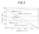
- FIG. 2 is a diagram showing relations between retransmission rate and throughput when retransmission is requested. The relations are shown in a calculation formula or a map relating retransmission rate to throughput.
- the dotted lines in FIG. 2 show throughput without retransmission in case of 16QAM, 8PSK and QPSK among modulation schemes shown in Table 1.
- the solid line and the dash dotted line show the variation of throughput with retransmission in case of 16QAM and 8PSK respectively.
- FIG. 2 is a diagram showing the deterioration of throughput due to retransmission and the shown values are not particularly limited thereto.
- the throughput is substantially the same as in a modulation scheme having a one-level smaller multi-value number. That is, in this state the transmission efficiency is more favorable when used a modulation scheme having a one-level smaller multi-value number and requiring less power.
- the throughput when the retransmission rate is about 0.4 is substantially the same as the throughput in a modulation scheme having a one-level smaller multi-value number.
- the retransmission rate may be calculated for every 2-5 frames. That is, "Total number of frames" in the denominator of the formula (2) may be set to 2-5 frames.
- the throughput estimating unit 160 estimates current throughput from a current modulation scheme (first modulation scheme) and retransmission rate input from the data detection unit 130 and the retransmission rate calculation unit 150 respectively, based on relations shown in FIG. 2 .
- the current modulation scheme is 16QAM and the retransmission rate is 0. 4
- the throughput is estimated to be about 550 kbps.
- the modulation scheme request unit 170 selects the most adequate modulation scheme according to the quality of received signals and the retransmission rate input respectively from the signal quality estimating unit 140 and the retransmission rate calculation unit 150, and transmits a request for the selected modulation scheme to a base station via the transmission unit 180.
- the base station transmits a downlink signal to be transmitted next, to a mobile terminal (not shown) using the requested modulation scheme.
- the operation in the modulation scheme request unit 170 will be described in detail with reference to a flow chart.
- the transmission unit 180 forms transmitted data as transmission frames, changes frequency up to transmission frequency and outputs the transmission frames into the duplexer 110.
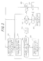
- FIG. 3 is a flow chart of the modulation scheme request unit 170.
- the modulation scheme request unit 170 selects an adequate modulation scheme (first modulation scheme) in the selection unit 171 according to the quality of received signals estimated by the signal quality estimating unit 140 and transmits the request to the base station, as well as resetting control variables j and k to 0 (Step S10).
- Step S12 the comparison unit 172 compares and determines whether the estimated throughput is lower than that in a modulation scheme having a one-level smaller multi-value number (second modulation scheme) than that in a current modulation scheme.
- the determination is performed by using the map of FIG.2 relating retransmission rate to throughout, or a calculation formula.
- the modulation scheme request unit 170 outputs data requesting the modulation scheme having a one-level smaller multi-value number into the transmission unit 180 and resets j to 0 (Step S13).
- Step S12 a determination method in Step S12.
- a current modulation scheme is 16 QAM
- the throughput with retransmission in case of 16 QAM is substantially the same as the ideal throughput in a modulation scheme having a one-level smaller multi-value number when the retransmission rate is about 0.4.
- BPSK one-level smaller multi-value number
- the modulation scheme request unit 170 can request a modulation scheme based on the quality of received signals estimated by the signal quality estimating unit 140 and thus the process returns to Step S10.
- k ⁇ 1 (k>1) is set in Step S15, it is meant that the retransmission rate is high and there is requested a modulation scheme having a one-level smaller multi-value number than that in a modulation scheme requested in the modulation scheme request unit 170 based on the quality of received signals estimated by the signal quality estimating unit 140 (i. e., it is meant that the process has passed Step S 13).
- L>random number value it is meant that, in a modulation scheme requested in Step S 13, the estimated throughput is higher, at the number of times of the random number in Step S12, than ideal throughput in a modulation scheme having a one-level smaller multi-value number than that in a current modulation scheme.
- Step S19 When "L>random number value" is determined in Step S19 , the process returns to Step S10 and the modulation scheme request unit 170 requests a modulation scheme based on the quality of received signals estimated again in the signal quality estimating unit 140. Otherwise, the modulation scheme request unit 170 maintains a current modulation scheme for a while or requests a modulation scheme based on throughput estimated from the retransmission rate.
- the communication method of the invention has been described as above as to the case in which the communication method of the invention is carried out as an apparatus.
- the communication method can be attained as software, namely a program or a storage medium with a program recorded. It will be appreciated that these also fall within the scope of the invention.
Landscapes
- Engineering & Computer Science (AREA)
- Signal Processing (AREA)
- Computer Networks & Wireless Communication (AREA)
- Quality & Reliability (AREA)
- Physics & Mathematics (AREA)
- Probability & Statistics with Applications (AREA)
- Mobile Radio Communication Systems (AREA)
- Detection And Prevention Of Errors In Transmission (AREA)
- Digital Transmission Methods That Use Modulated Carrier Waves (AREA)
- Communication Control (AREA)
Applications Claiming Priority (2)
| Application Number | Priority Date | Filing Date | Title |
|---|---|---|---|
| JP2006294238A JP2008113159A (ja) | 2006-10-30 | 2006-10-30 | 無線通信方法及びその装置 |
| PCT/JP2007/070533 WO2008053731A1 (en) | 2006-10-30 | 2007-10-22 | Wireless communication method and apparatus thereof |
Publications (2)
| Publication Number | Publication Date |
|---|---|
| EP2079211A1 true EP2079211A1 (de) | 2009-07-15 |
| EP2079211A4 EP2079211A4 (de) | 2012-10-24 |
Family
ID=39344074
Family Applications (1)
| Application Number | Title | Priority Date | Filing Date |
|---|---|---|---|
| EP07830267A Withdrawn EP2079211A4 (de) | 2006-10-30 | 2007-10-22 | Verfahren zur drahtlosen kommunikation und vorrichtung dafür |
Country Status (5)
| Country | Link |
|---|---|
| US (1) | US20100136915A1 (de) |
| EP (1) | EP2079211A4 (de) |
| JP (1) | JP2008113159A (de) |
| KR (1) | KR20090086205A (de) |
| WO (1) | WO2008053731A1 (de) |
Cited By (1)
| Publication number | Priority date | Publication date | Assignee | Title |
|---|---|---|---|---|
| KR101284743B1 (ko) | 2009-07-21 | 2013-07-17 | 지티이 코포레이션 | 업링크중 재전송 판정에 사용되는 방법 및 장치 |
Families Citing this family (2)
| Publication number | Priority date | Publication date | Assignee | Title |
|---|---|---|---|---|
| JP5997088B2 (ja) * | 2013-03-29 | 2016-09-28 | 株式会社日立製作所 | 動的帯域割当方法、olt、及びponシステム |
| EP3062553B1 (de) * | 2013-10-24 | 2021-06-02 | Mitsubishi Electric Corporation | Mobilstation und basisstation |
Family Cites Families (7)
| Publication number | Priority date | Publication date | Assignee | Title |
|---|---|---|---|---|
| EP1137217A1 (de) * | 2000-03-20 | 2001-09-26 | Telefonaktiebolaget Lm Ericsson | Verhandlung über ARQ-Parameter in einem Datenpaketübertragungssystem mit Verbindungsanpassung |
| GB2385754B (en) * | 2002-02-25 | 2005-01-12 | Toshiba Res Europ Ltd | Adaptive modulation for wireless networks |
| WO2004107695A1 (ja) * | 2003-05-27 | 2004-12-09 | Nec Corporation | 適応変調において適切な閾値で変調方式を選択するデータ通信装置 |
| JP4463813B2 (ja) * | 2003-07-25 | 2010-05-19 | パナソニック株式会社 | 伝送品質評価を備えたマルチキャリア送受信装置および方法 |
| JP4215601B2 (ja) * | 2003-09-05 | 2009-01-28 | 富士通株式会社 | 無線通信装置 |
| JP4376658B2 (ja) * | 2004-02-27 | 2009-12-02 | 京セラ株式会社 | 基地局装置、移動体端末及び移動体通信システム |
| JP4628150B2 (ja) | 2004-03-29 | 2011-02-09 | パナソニック株式会社 | 通信装置及び通信方法 |
-
2006
- 2006-10-30 JP JP2006294238A patent/JP2008113159A/ja not_active Withdrawn
-
2007
- 2007-10-22 EP EP07830267A patent/EP2079211A4/de not_active Withdrawn
- 2007-10-22 KR KR1020097009053A patent/KR20090086205A/ko not_active Ceased
- 2007-10-22 US US12/447,642 patent/US20100136915A1/en not_active Abandoned
- 2007-10-22 WO PCT/JP2007/070533 patent/WO2008053731A1/ja not_active Ceased
Cited By (1)
| Publication number | Priority date | Publication date | Assignee | Title |
|---|---|---|---|---|
| KR101284743B1 (ko) | 2009-07-21 | 2013-07-17 | 지티이 코포레이션 | 업링크중 재전송 판정에 사용되는 방법 및 장치 |
Also Published As
| Publication number | Publication date |
|---|---|
| JP2008113159A (ja) | 2008-05-15 |
| KR20090086205A (ko) | 2009-08-11 |
| EP2079211A4 (de) | 2012-10-24 |
| WO2008053731A1 (en) | 2008-05-08 |
| US20100136915A1 (en) | 2010-06-03 |
Similar Documents
| Publication | Publication Date | Title |
|---|---|---|
| US7277492B2 (en) | Transmission apparatus, transmission control method, reception apparatus, and reception control method | |
| EP0963074B1 (de) | Schätzung der Konstellationsgrösse für Systemen mit adaptiver Modulation | |
| US7418241B2 (en) | System and techniques for enhancing the reliability of feedback in a wireless communications system | |
| US6359934B1 (en) | Adaptive modulation method | |
| US8861499B1 (en) | Data rate adaptation in multiple-in-multiple-out systems | |
| US7298784B2 (en) | Reception method, reception apparatus and wireless transmission system using adaptive modulation scheme | |
| JP3898192B2 (ja) | 適応変調方式を使用した無線通信方法及び無線通信装置 | |
| US7656960B2 (en) | Adaptive modulation method and coding rate control method | |
| US20070087772A1 (en) | Method for uplink scheduling in a wireless mobile communication system | |
| US7768984B2 (en) | Apparatus and method for receiving a signal in a communication system | |
| US7352696B2 (en) | Method and apparatus to select an adaptation technique in a wireless network | |
| Kamio et al. | Performance of modulation-level-controlled adaptive-modulation under limited transmission delay time for land mobile communications | |
| US20040213182A1 (en) | Apparatus and method for controlling a reverse rate in a mobile communication system supporting packet data service | |
| US20050136844A1 (en) | Method and apparatus for automatic data rate control using channel correlation in a wireless communication system | |
| US20050164644A1 (en) | Radio communication device receiver device and reception manner selecting method | |
| JP2005252745A (ja) | 適応変調方法並びにデータレート制御方法 | |
| EP2163060B1 (de) | Setzen des leistungspegels der informationselemente in der ofdma-map gemäss dem kanalzustand | |
| EP2502377B1 (de) | Verfahren und Basisstation zur Detektion eines HARQ-ACK Kodewortes | |
| JP3993469B2 (ja) | 移動通信システムおよび適応変調方法 | |
| US8750236B2 (en) | Selecting a transmission mode between a subscriber and a base station | |
| US20100136915A1 (en) | Wireless Communication Method and Apparatus Therefor | |
| US8325859B2 (en) | Communication device and control method | |
| CN101317346A (zh) | 无线基站装置和无线基站装置的控制方法 | |
| JP4206104B2 (ja) | 適応変調方式を使用した無線通信方法及び無線通信装置 | |
| JP2007158483A (ja) | 基地局及び無線通信方法 |
Legal Events
| Date | Code | Title | Description |
|---|---|---|---|
| PUAI | Public reference made under article 153(3) epc to a published international application that has entered the european phase |
Free format text: ORIGINAL CODE: 0009012 |
|
| 17P | Request for examination filed |
Effective date: 20090527 |
|
| AK | Designated contracting states |
Kind code of ref document: A1 Designated state(s): AT BE BG CH CY CZ DE DK EE ES FI FR GB GR HU IE IS IT LI LT LU LV MC MT NL PL PT RO SE SI SK TR |
|
| DAX | Request for extension of the european patent (deleted) | ||
| A4 | Supplementary search report drawn up and despatched |
Effective date: 20120921 |
|
| RIC1 | Information provided on ipc code assigned before grant |
Ipc: H04L 27/00 20060101AFI20120917BHEP Ipc: H04L 1/16 20060101ALN20120917BHEP Ipc: H04L 1/20 20060101ALN20120917BHEP Ipc: H04L 1/00 20060101ALI20120917BHEP |
|
| STAA | Information on the status of an ep patent application or granted ep patent |
Free format text: STATUS: THE APPLICATION IS DEEMED TO BE WITHDRAWN |
|
| 18D | Application deemed to be withdrawn |
Effective date: 20130410 |