EP2079278A2 - Unidirektionale Leuchtdiodentreiberschaltung in bidirektionaler paralleler Stromrezonanz - Google Patents
Unidirektionale Leuchtdiodentreiberschaltung in bidirektionaler paralleler Stromrezonanz Download PDFInfo
- Publication number
- EP2079278A2 EP2079278A2 EP09250084A EP09250084A EP2079278A2 EP 2079278 A2 EP2079278 A2 EP 2079278A2 EP 09250084 A EP09250084 A EP 09250084A EP 09250084 A EP09250084 A EP 09250084A EP 2079278 A2 EP2079278 A2 EP 2079278A2
- Authority
- EP
- European Patent Office
- Prior art keywords
- impedance
- directional
- power
- light emitting
- emitting diode
- Prior art date
- Legal status (The legal status is an assumption and is not a legal conclusion. Google has not performed a legal analysis and makes no representation as to the accuracy of the status listed.)
- Withdrawn
Links
- 230000001939 inductive effect Effects 0.000 claims abstract description 77
- 239000003990 capacitor Substances 0.000 claims description 49
- 238000004146 energy storage Methods 0.000 claims description 6
- 238000004804 winding Methods 0.000 description 45
- 238000010586 diagram Methods 0.000 description 26
- 239000007787 solid Substances 0.000 description 11
- 230000000694 effects Effects 0.000 description 8
- 238000007599 discharging Methods 0.000 description 7
- 230000002159 abnormal effect Effects 0.000 description 4
- 238000009434 installation Methods 0.000 description 4
- 230000010349 pulsation Effects 0.000 description 4
- 238000006243 chemical reaction Methods 0.000 description 2
- 238000009825 accumulation Methods 0.000 description 1
- 239000003086 colorant Substances 0.000 description 1
- 230000000750 progressive effect Effects 0.000 description 1
- 239000002699 waste material Substances 0.000 description 1
Images



Classifications
-
- H—ELECTRICITY
- H05—ELECTRIC TECHNIQUES NOT OTHERWISE PROVIDED FOR
- H05B—ELECTRIC HEATING; ELECTRIC LIGHT SOURCES NOT OTHERWISE PROVIDED FOR; CIRCUIT ARRANGEMENTS FOR ELECTRIC LIGHT SOURCES, IN GENERAL
- H05B45/00—Circuit arrangements for operating light-emitting diodes [LED]
- H05B45/30—Driver circuits
- H05B45/37—Converter circuits
Definitions
- the uni-directional light emitting diode drive circuit in bi-directional power parallel resonance is disclosed by that by using a bi-directional power as the power source, the first impedance is constituted by the capacitive impedance component, or the inductive impedance component or the resistive impedance component, and the second impedance is constituted by the inductive impedance component and the capacitive impedance component in parallel connection, whereof its inherent parallel resonance frequency is the same as the pulse period of the pulsed power to appear parallel resonance status, whereof it characterized in that two ends of the first impedance and the second impedance in series connection are provided to receive the bi-directional power, whereby the bi-directional power input is divided by the first impedance and the second impedance of parallel resonance in series connection to produce a divided power which is rectified by a rectifier device to an uni-directional DC power, whereby to drive the uni-directional conducting light emitting diode.
- the conventional light emitting diode drive circuit using AC or DC power source is usually series connected with current limit resistors as the impedance to limit the current to the light emitting diode, whereof the voltage drop of the series connected resistive impedance always result in waste of power and accumulation of heat which are the imperfections.
- the present invention is disclosed by that a bi-directional power is used as the power source, the first impedance is constituted by capacitive impedance, or inductive impedance component, or resistive impedance component;
- At least one capacitive impedance and at least one inductive impedance component in parallel connection constitute a second impedance, whereof the inherent parallel resonance frequency of the second impedance is the same as the frequency or period of a bi-directional power to generate a low energy-consuming alternated polarity energy storage status of a parallel resonance frequency.
- the two ends of the first impedance and the second impedance in series connection are provided to receive the bi-directional power as the following:
- the bi-directional power input is divided by the first impedance and the second impedance of parallel resonance in series connection, whereof their divided power is rectified by a rectifier device to an uni-directional DC power to drive the uni-directional conducting light emitting diode, whereof it is characterized in that if a high frequency bi-directional power is used in the uni-directional light emitting diode drive circuit of bi-directional power parallel resonance, then its volume and weight can be effectively reduced as well as the cost can be lowered.
- the uni-directional light emitting diode drive circuit in bi-directional power parallel resonance, whereof at least one capacitive impedance component, or inductive impedance component or resistive impedance component constitutes the first impedance, while at least one capacitive impedance component and at least one inductive impedance component are in parallel connection to constitute the second impedance, whereof in a bi-directional power input, their inherent parallel resonance frequency after the parallel connection is the same as the frequency or period of the bi-directional power to appear parallel resonance status;
- the two ends of at least one first impedance and at least one second impedance in series connection are provided to receive a bi-directional power input from power source, whereby the bi-directional power from power source forms the divided power at the second impedance in parallel resonance, and the said corresponding divided power of the second impedance in parallel resonance is provided to the AC input ends of a rectifier device, and through DC output ends of the said rectifier device to provide DC power output;
- At least one light emitting diode constitutes the uni-directional conducting light emitting diode set to be driven by the DC power output from the rectifier device;
- the input ends of at least one rectifier device are provided to receive the divided power across the two ends of the first impedance, or to receive the divided power from the second impedance;
- At least one uni-directional conducting light emitting diode set is driven by the rectified DC power, whereby to constitute the uni-directional light emitting diode drive circuit of pulsed power in parallel resonance.
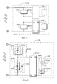
- FIG. 1 is the schematic block diagram of the uni-directional light emitting diode drive circuit in bi-directional power parallel resonance, in which the circuit function is operated through the uni-directional light emitting diode drive circuit (U100) as shown in FIG. 1 , whereof it is comprised of:
- the uni-directional conducting light emitting diode set (L100) can be selected to be installed one set or more than one sets as needed, whereof it is arranged to be driven by the DC power outputted from the rectifier device (BR101);
- the light emitting diode (LED101) which constitutes the uni-directional conducting light emitting diode set (L100) in the uni-directional light emitting diode drive circuit (U100) of the uni-directional light emitting diode drive circuit in bi-directional power parallel resonance includes the following selections:
- FIG. 5 is a circuit example schematic diagram illustrating that a charge/discharge device is parallel connected across the two ends of the light emitting diode in the circuit of FIG. 3 .
- FIG. 4 and FIG. 5 are comprised of that:
- the first impedance (Z101), the second impedance (Z102), the rectifier device (BR101) and the uni-directional conducting light emitting diode set (L100) as well as the light emitting diode (LED101) and various aforesaid optional auxiliary circuit components as shown in the circuit examples of FIGS. 1 ⁇ 5 are based on application needs, whereof they can be optionally installed or not installed as needed and the installation quantity include constitution by one, wherein if more than one are selected, the corresponding polarity relationship shall be determined based on circuit function requirement to do series connection, or parallel connection or series and parallel connections; thereof it is constituted as the following:
- active modulating circuit devices can be further optionally combined as needed, whereof various applied circuits are as following:
- the uni-directional light emitting diode drive circuit of bi-directional power in parallel resonance in which the optionally installed inductive impedance component (I200) of the second impedance (Z102) can be further replaced by the power supply side winding of a transformer with inductive effect, whereof the transformer can be a self-coupled transformer (ST200) with self-coupled voltage change winding or a transformer (IT200) with separating type voltage change winding;
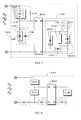
- FIG. 11 is a circuit example schematic diagram of the present invention illustrating that the inductive impedance component of the second impedance is replaced by the self-coupled voltage change power supply side winding of the self-coupled transformer thereby to constitute a voltage rise, whereof as shown in FIG.
- the self-coupled transformer (ST200) has a self-coupled voltage change winding (W0) with voltage raising function
- the b, c taps of the self-coupled voltage change winding (W0) of the self-coupled transformer (ST200) are the power supply side which replace the inductive impedance component (I200) of the second impedance (Z102) to be parallel connected with a capacitor (C200), whereof its inherent parallel resonance frequency after the parallel connection is the same as the frequency or period of the bi-directional power from the power source to appear a parallel resonance status, thereby to constitute the second impedance (Z102) which is series connected with the capacitor (C100) of the first impedance (Z101), further the capacitor (C200) can be optionally selected parallel connected with the a, c taps or b, c taps of the self-coupled transformer (ST200), or other selected taps as needed, whereof the a, c output taps of the self-coupled voltage change winding (W0) of the self-
- FIG. 12 is a circuit example schematic diagram of the present invention illustrating that the inductive impedance component of the second impedance is replaced by the self-coupled voltage change power supply side winding of the self-coupled transformer thereby to constitute a voltage drop, whereof as shown in FIG.
- the self-coupled transformer (ST200) has a self-coupled voltage change winding (W0) with voltage drop function
- the a, c ends of the self-coupled voltage change winding (W0) of the self-coupled transformer (ST200) are the power supply side which replace the inductive impedance component (I200) of the second impedance (Z102) to be parallel connected with the capacitor (C200), whereof its inherent parallel resonance frequency after parallel connection is the same the frequency or period of the bi-directional power from the power source to appear a parallel resonance status, thereby to constitute the second impedance (Z102) which is series connected with the capacitor (C100) of the first impedance (Z101), further, the capacitor (C200) can be optionally parallel connected with the a, c taps or b, c taps of the self-coupled transformer (ST200), or other selected taps as needed, whereof the b, c output ends of the self-coupled voltage change winding (W0) of the self-coupled transformer (
- FIG. 13 is a circuit example schematic diagram of the present invention illustrating that the inductive impedance component of the second impedance is replaced by the primary side winding of the separating type transformer with separating type voltage change winding, whereof as shown in FIG. 13 , the separating type transformer (IT200) is comprised of a primary side winding (W1) and a secondary side winding (W2), in which the primary side winding (W1) and the secondary side winding (W2) are separated, whereof the primary side winding (W1) is parallel connected with the capacitor (C200), whereof its inherent parallel resonance frequency after parallel connection is the same as the frequency or period of the bi-directional power from the power source to appear a parallel resonance status, thereby to constitute the second impedance (Z102) which is series connected with the capacitor (C100) of the first impedance (Z101), further, the capacitor (C200) can be optionally parallel connected with the a, c taps or b, c taps of the self-coupled transformer (ST200), or other selected tap
- the inductive impedance component (I200) of the second impedance (Z102) is replaced by the power supply side winding of the transformer and is parallel connected with the capacitor (C200) to appear parallel resonance, whereby to constitute the second impedance (Z102), whereof the secondary side of the separating type transformer (IT200) provides AC power of voltage rise or voltage drop to the AC input ends of the rectifier device (BR101) while the DC output ends of the rectifier device (BR101) are used to drive the uni-directional conducting light emitting diode set (L100).
- Color of the individual light emitting diodes (LED101) of the uni-directional conducting light emitting diode set (L100) in the uni-directional light emitting diode drive circuit (U100) of the uni-directional light emitting diode drive circuit in bi-directional power parallel resonance can be optionally selected to be constituted by one or more than one colors.
- the relationships of location arrangement between the individual light emitting diodes (LED101) of the uni-directional conducting light emitting diode set (L100) in the uni-directional light emitting diode drive circuit (U100) of the uni-directional light emitting diode drive circuit in bi-directional power parallel resonance include the following: 1) sequentially linear arrangement; 2) sequentially distributed in a plane; 3) crisscross-linear arrangement; 4) crisscross distribution in a plane; 5) arrangement based on particular geometric positions in a plane; 6) arrangement based on 3D geometric position.
- the uni-directional light emitting diode drive circuit in bi-directional power parallel resonance in which the embodiments of its uni-directional light emitting diode drive circuit (U100) are constituted by circuit components which include: 1) It is constituted by individual circuit components which are inter-connected; 2) At least two circuit components are combined to at least two partial functioning units which are further inter-connected; 3) All components are integrated together to one structure.
- progressive performances of power saving, low heat loss and low cost can be provided by the uni-directional light emitting diode drive circuit in bi-directional power parallel resonance through the charging/discharging by the uni-polar capacitor to drive the light emitting diode.
- Preferably embodiments provide a uni-directional light emitting diode drive circuit in bi-directional power parallel resonance, which is that a bi-directional power is used as the power source, the first impedance is constituted by capacitive impedance, or inductive impedance component, or resistive impedance component;
- At least one capacitive impedance and at least one inductive impedance component in parallel connection constitute the second impedance, whereof the inherent parallel resonance frequency of the second impedance is the same as the frequency or period of a bi-directional power to generate a low energy-consuming alternated polarity energy storage status of a parallel resonance frequency;
- the two ends of the first impedance and the second impedance in series connection are provided to receive the bi-directional power as the following:
- the bi-directional power input is divided by the first impedance and the second impedance of parallel resonance in series connection, whereof their divided power is rectified by a rectifier device to an uni-directional DC power to drive the uni-directional conducting light emitting diode, whereof it is characterized in that if a high frequency bi-directional power is used in the uni-directional light emitting diode drive circuit of bi-directional power parallel resonance, then its volume and weight can be effectively reduced as well as the cost can be lowered;
- the first impedance, the second impedance, the rectifier device and the uni-directional conducting light emitting diode set as well as the light emitting diode and various optional auxiliary circuit components are based on application needs, whereof they can be optionally installed or not installed as needed and the installation quantity include constitution by one, wherein if more than one are selected, the corresponding polarity relationship shall be determined based on circuit function requirement to do series connection, or parallel connection or series and parallel connections.
- At least one capacitive impedance component, or inductive impedance component or resistive impedance component constitutes the first impedance, while at least one capacitive impedance component and at least one inductive impedance component are in parallel connection to constitute the second impedance, whereof in a bi-directional power input, their inherent parallel resonance frequency after the parallel connection is the same as the frequency or period of the bi-directional power to appear parallel resonance status;
- the two ends of at least one first impedance and at least one second impedance in series connection are provided to receive a bi-directional power input from power source, whereby the bi-directional power from power source forms the divided power at the second impedance in parallel resonance, and the said corresponding divided power of the second impedance in parallel resonance is provided to the AC input ends of a rectifier device, and through DC output ends of the said rectifier device to provide DC power output;
- At least one light emitting diode constitutes the uni-directional conducting light emitting diode set to be driven by the DC power output from the rectifier device;
- the input ends of at least one rectifier device are provided to receive the divided power across the two ends of the first impedance, or to receive the divided power from the second impedance;
- At least one uni-directional conducting light emitting diode set is driven by the rectified DC power, whereby to constitute the uni-directional light emitting diode drive circuit of pulsed power in parallel resonance; whereof it is comprised of:
- the uni-directional conducting light emitting diode set (L100) can be selected to be installed one set or more than one sets as needed, whereof it is arranged to be driven by the DC power outputted from the rectifier device (BR101).
- the uni-directional light emitting diode drive circuit (U100) is by means of the uni-directional conducting light emitting diode set (L100) through a divided power distribution effect formed by the parallel connection between the rectifier device (BR101) and the second impedance (Z102) to reduce the voltage variation rate across the two ends of uni-directional conducting light emitting diode set (L100) corresponding to the power source of voltage variation.
- the light emitting diode (LED101) which constitutes the uni-directional conducting light emitting diode set (L100) in the uni-directional light emitting diode drive circuit (U100) includes the uni-directional conducting light emitting diode set (L100) is constituted by a forward current polarity light emitting diode, or two or more than two forward current polarity light emitting diodes in series connection or parallel connection, or three or more than three forward current polarity light emitting diodes in series connection, parallel connection or series and parallel connection, whereof one set or more than one sets of the uni-directional conducting light emitting diode set (L100) can be optionally selected as needed.
- a zener diode can be further parallel connected across the two ends of the light emitting diode (LED101) of the uni-directional conducting light emitting diode set (L100) in the uni-directional light emitting diode drive circuit (U100) of the uni-directional light emitting diode drive circuit in bi-directional power parallel resonance, or the zener diode can be first series connected with at least one diode to jointly produce the function of zener voltage effect, then to be parallel connected across the two ends of the light emitting diode (LED101); whereof it is constituted by the following:
- the light emitting diode (LED101) can be further installed with a charge/discharge device (ESD101), whereof random power charging or discharging can be provided by the charge/discharge device (ESD101) to stabilize the lighting stability of the light emitting diode (LED101), whereby to reduce its lighting pulsation, or in case of power supply off, reserved power can be supplied by the charge/discharge device (ESD101) to drive the light emitting diode (LED101) to emit light continuously; whereof it is comprised of that:
- an uni-directional conducting light emitting diode set (L100) or more than one uni-directional conducting light emitting diode sets (L100) in series connection, parallel connection or series and parallel connection can be optionally installed as needed in the uni-directional light emitting diode drive circuit (U100), whereof if one or more than one sets are installed, it can be driven by the divided power of a common impedance (Z102) through its matched rectifier device (BR101), or it can be individually driven by the divided power of multiple second impedances (Z102) in series or parallel connection, whereof each of the multiple second impedances (Z102) is installed with a rectifier device (BR101) individually to drive its corresponding matched uni-directional conducting light emitting diode set (L100) individually.
- BR101 rectifier device
- ESD101 charge/discharge device
- the light emitting diode (LED101) of the uni-directional conducting light emitting diode set (L100) is driven by continuous DC power to emit light.
- the charge/discharge device (ESD101) is not installed, current conduction to light emitting diode (LED101) is intermittent, whereby referring to the input voltage wave shape and duty cycle of current conduction, the light emitting forward current and the peak of light emitting forward voltage of each light emitting diode in the uni-directional conducting light emitting diode set (L100) can be correspondingly selected for the light emitting diode (LED101); if current conduction to light emitting diode (LED101) is intermittent, the peak of light emitting forward voltage can be correspondingly selected based on the duty cycle of current conduction as long as the principle of that the peak of light emitting forward voltage does not damage the light emitting diode (LED 101) is followed.
- the charge/discharge device (ESD101) is not installed, based on the value and wave shape of the light emitting forward voltage, the corresponding current value and wave shape from the forward voltage vs. forward current ratio are produced; however the peak of light emitting forward current shall follow the principle not to damage the light emitting diode (LED101).
- the bi-directional power includes that:
- the uni-directional light emitting diode drive circuit in bi-directional power parallel resonance is series connected to the power modulator of series connection type, whereof the power modulator of series connection type is constituted by the following:
- the uni-directional light emitting diode drive circuit in bi-directional power parallel resonance is parallel connected to a power modulator of parallel connection type, whereof the power modulator of parallel connection type is constituted by the following:
- the uni-directional light emitting diode drive circuit in bi-directional power parallel resonance is driven by the power outputted from a DC to AC inverter, whereof it is mainly comprised of:
- the uni-directional light emitting diode drive circuit (U100) is arranged to be series connected with a least one conventional impedance component (500) and to be further parallel connected with the power source, whereof the impedance (500) includes that:
- the optionally installed inductive impedance component (I200) of the second impedance (Z102) can be further replaced by the power supply side winding of a transformer with inductive effect, whereof the self-coupled transformer (ST200) has a self-coupled voltage change winding (W0) with voltage raising function, the b, c taps of the self-coupled voltage change winding (W0) of the self-coupled transformer (ST200) are the power supply side which replace the inductive impedance component (I200) of the second impedance (Z102) to be parallel connected with a capacitor (C200), whereof its inherent parallel resonance frequency after the parallel connection is the same as the frequency or period of the bi-directional power from the power source to appear a parallel resonance status, thereby to constitute the second impedance (Z102) which is series connected with the capacitor (C100) of the first impedance (Z101), further the capacitor (C200) can be optionally selected parallel connected with the a, c taps or b, c taps
- the optionally installed inductive impedance component (I200) of the second impedance (Z102) can be further replaced by the power supply side winding of a transformer with inductive effect, whereof the self-coupled transformer (ST200) has a self-coupled voltage change winding (W0) with voltage drop function, the a, c ends of the self-coupled voltage change winding (W0) of the self-coupled transformer (ST200) are the power supply side which replace the inductive impedance component (I200) of the second impedance (Z102) to be parallel connected with the capacitor (C200), whereof its inherent parallel resonance frequency after parallel connection is the same the frequency or period of the bi-directional power from the power source to appear a parallel resonance status, thereby to constitute the second impedance (Z102) which is series connected with the capacitor (C100) of the first impedance (Z101), further, the capacitor (C200) can be optionally parallel connected with the a, c taps or b, c taps of the self-
- the optionally installed inductive impedance component (I200) of the second impedance (Z102) can be further replaced by the power supply side winding of a transformer with inductive effect, whereof the separating type transformer (IT200) is comprised of a primary side winding (W1) and a secondary side winding (W2), in which the primary side winding (W1) and the secondary side winding (W2) are separated, whereof the primary side winding (W1) is parallel connected with the capacitor (C200), whereof its inherent parallel resonance frequency after parallel connection is the same as the frequency or period of the bi-directional power from the power source to appear a parallel resonance status, thereby to constitute the second impedance (Z102) which is series connected with the capacitor (C100) of the first impedance (Z101), further, the capacitor (C200) can be optionally parallel connected with the a, c taps or b, c taps of the self-coupled transformer (ST200), or other selected taps as needed, whereof the output voltage of the secondary side wind
- the inductive impedance component (I200) of the second impedance (Z102) is replaced by the power supply side winding of the transformer and is parallel connected with the capacitor (C200) to appear parallel resonance, whereby to constitute the second impedance (Z102), whereof the secondary side of the separating type transformer (IT200) provides AC power of voltage rise or voltage drop to the AC input ends of the rectifier device (BR101) while the DC output ends of the rectifier device (BR101) are used to drive the uni-directional conducting light emitting diode set (L100).
Landscapes
- Led Devices (AREA)
- Circuit Arrangement For Electric Light Sources In General (AREA)
Applications Claiming Priority (1)
| Application Number | Priority Date | Filing Date | Title |
|---|---|---|---|
| US2082508P | 2008-01-14 | 2008-01-14 |
Publications (2)
| Publication Number | Publication Date |
|---|---|
| EP2079278A2 true EP2079278A2 (de) | 2009-07-15 |
| EP2079278A3 EP2079278A3 (de) | 2011-03-30 |
Family
ID=40626772
Family Applications (1)
| Application Number | Title | Priority Date | Filing Date |
|---|---|---|---|
| EP09250084A Withdrawn EP2079278A3 (de) | 2008-01-14 | 2009-01-14 | Unidirektionale Leuchtdiodentreiberschaltung in bidirektionaler paralleler Stromrezonanz |
Country Status (6)
| Country | Link |
|---|---|
| US (1) | US20090179886A1 (de) |
| EP (1) | EP2079278A3 (de) |
| JP (1) | JP2009170916A (de) |
| CN (1) | CN101489326A (de) |
| CA (1) | CA2649540A1 (de) |
| TW (1) | TW200932061A (de) |
Cited By (5)
| Publication number | Priority date | Publication date | Assignee | Title |
|---|---|---|---|---|
| GB2464211A (en) * | 2008-10-08 | 2010-04-14 | Holdip Ltd | Power adaptor having resonant circuit for solid state lighting |
| US8242711B2 (en) | 2007-03-30 | 2012-08-14 | Hold IP Limited | Lighting systems |
| US9124193B2 (en) | 2008-10-08 | 2015-09-01 | Holdip Limited | Power adaptors |
| US9736894B2 (en) | 2013-12-12 | 2017-08-15 | Verdi Vision Limited | Improvements relating to power adaptors |
| US10790762B2 (en) | 2013-05-23 | 2020-09-29 | Adp Corporate Limited | Relating to power adaptors |
Families Citing this family (6)
| Publication number | Priority date | Publication date | Assignee | Title |
|---|---|---|---|---|
| KR20130080035A (ko) * | 2010-09-08 | 2013-07-11 | 후이저우 라이트 엔진 리미티드 | 전자식 트랜스포머 구동 led 장치를 위한 안정화 회로 |
| CN102185491B (zh) * | 2011-04-07 | 2014-04-09 | 中国科学院电工研究所 | 混联电桥型阻抗网络功率变换器 |
| CN103731950B (zh) * | 2012-10-12 | 2016-08-24 | 台达电子企业管理(上海)有限公司 | 照明装置及其降压方法 |
| WO2020049853A1 (ja) * | 2018-09-05 | 2020-03-12 | 三菱電機株式会社 | 非接触給電システムおよび送電装置 |
| US20200361040A1 (en) * | 2019-05-14 | 2020-11-19 | Illinois Tool Works Inc. | Method and apparatus for mechanically coupling a motor to an electrically isolated pump |
| CN114269039B (zh) * | 2022-03-01 | 2022-06-14 | 南昌硅基半导体科技有限公司 | 一种高电光调制带宽的led器件 |
Family Cites Families (11)
| Publication number | Priority date | Publication date | Assignee | Title |
|---|---|---|---|---|
| US3875421A (en) * | 1973-05-14 | 1975-04-01 | Needs Inc | Bicycle light system |
| US5939837A (en) * | 1997-07-15 | 1999-08-17 | Magnetek, Inc. | Electronic ballast circuit for independently increasing the power factor and decreasing the crest factor |
| EP1137151A4 (de) * | 1998-09-07 | 2004-03-31 | Kenichi Suzuki | Stromsparschaltung |
| EP1164689A3 (de) * | 2000-06-16 | 2003-09-10 | FORFAS, (trading as PEI Technologies) | Einstufiger Wechselstrom/Gleichstrom-Wandler |
| US20020043943A1 (en) * | 2000-10-10 | 2002-04-18 | Menzer Randy L. | LED array primary display light sources employing dynamically switchable bypass circuitry |
| US6411045B1 (en) * | 2000-12-14 | 2002-06-25 | General Electric Company | Light emitting diode power supply |
| US6580230B2 (en) * | 2001-01-22 | 2003-06-17 | 1513660 Ontario Inc. | Energy conservation dimmer device for gaseous discharge devices |
| US6985370B2 (en) * | 2002-05-24 | 2006-01-10 | David Kerstetter | AC power line filter |
| DE102006022819A1 (de) * | 2005-05-23 | 2007-01-04 | Infineon Technologies Ag | Schaltungsanordnung zum Versorgen einer Last mit einem Ausgangsstrom |
| DE102006022845B4 (de) * | 2005-05-23 | 2016-01-07 | Infineon Technologies Ag | Ansteuerschaltung für eine Schaltereinheit einer getakteten Leistungsversorgungsschaltung und Resonanzkonverter |
| US7889519B2 (en) * | 2006-01-12 | 2011-02-15 | Massachusetts Institute Of Technology | Methods and apparatus for a resonant converter |
-
2009
- 2009-01-12 US US12/351,918 patent/US20090179886A1/en not_active Abandoned
- 2009-01-13 CA CA002649540A patent/CA2649540A1/en not_active Abandoned
- 2009-01-13 TW TW098101067A patent/TW200932061A/zh unknown
- 2009-01-14 EP EP09250084A patent/EP2079278A3/de not_active Withdrawn
- 2009-01-14 JP JP2009005359A patent/JP2009170916A/ja active Pending
- 2009-01-14 CN CNA200910002673XA patent/CN101489326A/zh active Pending
Cited By (7)
| Publication number | Priority date | Publication date | Assignee | Title |
|---|---|---|---|---|
| US8242711B2 (en) | 2007-03-30 | 2012-08-14 | Hold IP Limited | Lighting systems |
| GB2464211A (en) * | 2008-10-08 | 2010-04-14 | Holdip Ltd | Power adaptor having resonant circuit for solid state lighting |
| GB2464211B (en) * | 2008-10-08 | 2013-04-10 | Holdip Ltd | Improvements relating to lighting systems |
| US9124193B2 (en) | 2008-10-08 | 2015-09-01 | Holdip Limited | Power adaptors |
| US9888533B2 (en) | 2008-10-08 | 2018-02-06 | Holdip Limited | Power adaptors |
| US10790762B2 (en) | 2013-05-23 | 2020-09-29 | Adp Corporate Limited | Relating to power adaptors |
| US9736894B2 (en) | 2013-12-12 | 2017-08-15 | Verdi Vision Limited | Improvements relating to power adaptors |
Also Published As
| Publication number | Publication date |
|---|---|
| US20090179886A1 (en) | 2009-07-16 |
| EP2079278A3 (de) | 2011-03-30 |
| CA2649540A1 (en) | 2009-07-14 |
| JP2009170916A (ja) | 2009-07-30 |
| TW200932061A (en) | 2009-07-16 |
| CN101489326A (zh) | 2009-07-22 |
Similar Documents
| Publication | Publication Date | Title |
|---|---|---|
| EP2079278A2 (de) | Unidirektionale Leuchtdiodentreiberschaltung in bidirektionaler paralleler Stromrezonanz | |
| US8063571B2 (en) | Bi-directional light emitting diode drive circuit in bi-directional divided power impedance | |
| US8063587B2 (en) | Bi-directional light emitting diode drive circuit in bi-directional power parallel resonance | |
| US8054004B2 (en) | Bipolar (dis)charging LED drive method and circuit thereof | |
| US8067901B2 (en) | Bi-directional light emitting diode drive circuit in pulsed power parallel resonance | |
| US8072161B2 (en) | Bi-directional light emitting diode drive circuit in pulsed power non-resonance | |
| CA2649545C (en) | Uni-directional light emitting diode drive circuit in bi-directional divided power impedance | |
| US20090224688A1 (en) | Unipolar (dis)charging led drive method and circuit thereof | |
| US8049428B2 (en) | Uni-directional light emitting diode drive circuit in pulsed power series resonance | |
| US8058820B2 (en) | Uni-directional light emitting diode drive circuit in pulsed power parallel resonance | |
| US8058814B2 (en) | Bi-directional light emitting diode drive circuit in pulsed power series resonance | |
| US8054007B2 (en) | Bi-directional light emitting diode drive circuit in bi-directional power series resonance | |
| US8049440B2 (en) | Uni-directional light emitting diode drive circuit in pulsed power non-resonance | |
| US8164271B2 (en) | Uni-directional light emitting diode drive circuit in bi-directional power series resonance |
Legal Events
| Date | Code | Title | Description |
|---|---|---|---|
| PUAI | Public reference made under article 153(3) epc to a published international application that has entered the european phase |
Free format text: ORIGINAL CODE: 0009012 |
|
| AK | Designated contracting states |
Kind code of ref document: A2 Designated state(s): AT BE BG CH CY CZ DE DK EE ES FI FR GB GR HR HU IE IS IT LI LT LU LV MC MK MT NL NO PL PT RO SE SI SK TR |
|
| AX | Request for extension of the european patent |
Extension state: AL BA RS |
|
| PUAL | Search report despatched |
Free format text: ORIGINAL CODE: 0009013 |
|
| AK | Designated contracting states |
Kind code of ref document: A3 Designated state(s): AT BE BG CH CY CZ DE DK EE ES FI FR GB GR HR HU IE IS IT LI LT LU LV MC MK MT NL NO PL PT RO SE SI SK TR |
|
| AX | Request for extension of the european patent |
Extension state: AL BA RS |
|
| AKY | No designation fees paid | ||
| REG | Reference to a national code |
Ref country code: DE Ref legal event code: R108 |
|
| STAA | Information on the status of an ep patent application or granted ep patent |
Free format text: STATUS: THE APPLICATION IS DEEMED TO BE WITHDRAWN |
|
| REG | Reference to a national code |
Ref country code: DE Ref legal event code: R108 Effective date: 20111207 |
|
| 18D | Application deemed to be withdrawn |
Effective date: 20110802 |