EP2079409B1 - Gasweiterleitung in einer gefässzugangsvorrichtung - Google Patents
Gasweiterleitung in einer gefässzugangsvorrichtung Download PDFInfo
- Publication number
- EP2079409B1 EP2079409B1 EP07844823.0A EP07844823A EP2079409B1 EP 2079409 B1 EP2079409 B1 EP 2079409B1 EP 07844823 A EP07844823 A EP 07844823A EP 2079409 B1 EP2079409 B1 EP 2079409B1
- Authority
- EP
- European Patent Office
- Prior art keywords
- septum
- receptacle
- gas chamber
- volume
- access device
- Prior art date
- Legal status (The legal status is an assumption and is not a legal conclusion. Google has not performed a legal analysis and makes no representation as to the accuracy of the status listed.)
- Active
Links
Images



Classifications
-
- A—HUMAN NECESSITIES
- A61—MEDICAL OR VETERINARY SCIENCE; HYGIENE
- A61M—DEVICES FOR INTRODUCING MEDIA INTO, OR ONTO, THE BODY; DEVICES FOR TRANSDUCING BODY MEDIA OR FOR TAKING MEDIA FROM THE BODY; DEVICES FOR PRODUCING OR ENDING SLEEP OR STUPOR
- A61M39/00—Tubes, tube connectors, tube couplings, valves, access sites or the like, specially adapted for medical use
- A61M39/02—Access sites
- A61M39/04—Access sites having pierceable self-sealing members
- A61M39/045—Access sites having pierceable self-sealing members pre-slit to be pierced by blunt instrument
-
- A—HUMAN NECESSITIES
- A61—MEDICAL OR VETERINARY SCIENCE; HYGIENE
- A61M—DEVICES FOR INTRODUCING MEDIA INTO, OR ONTO, THE BODY; DEVICES FOR TRANSDUCING BODY MEDIA OR FOR TAKING MEDIA FROM THE BODY; DEVICES FOR PRODUCING OR ENDING SLEEP OR STUPOR
- A61M39/00—Tubes, tube connectors, tube couplings, valves, access sites or the like, specially adapted for medical use
- A61M39/22—Valves or arrangement of valves
- A61M39/26—Valves closing automatically on disconnecting the line and opening on reconnection thereof
-
- A—HUMAN NECESSITIES
- A61—MEDICAL OR VETERINARY SCIENCE; HYGIENE
- A61M—DEVICES FOR INTRODUCING MEDIA INTO, OR ONTO, THE BODY; DEVICES FOR TRANSDUCING BODY MEDIA OR FOR TAKING MEDIA FROM THE BODY; DEVICES FOR PRODUCING OR ENDING SLEEP OR STUPOR
- A61M39/00—Tubes, tube connectors, tube couplings, valves, access sites or the like, specially adapted for medical use
- A61M2039/0036—Tubes, tube connectors, tube couplings, valves, access sites or the like, specially adapted for medical use characterised by a septum having particular features, e.g. having venting channels or being made from antimicrobial or self-lubricating elastomer
-
- A—HUMAN NECESSITIES
- A61—MEDICAL OR VETERINARY SCIENCE; HYGIENE
- A61M—DEVICES FOR INTRODUCING MEDIA INTO, OR ONTO, THE BODY; DEVICES FOR TRANSDUCING BODY MEDIA OR FOR TAKING MEDIA FROM THE BODY; DEVICES FOR PRODUCING OR ENDING SLEEP OR STUPOR
- A61M39/00—Tubes, tube connectors, tube couplings, valves, access sites or the like, specially adapted for medical use
- A61M39/22—Valves or arrangement of valves
- A61M39/26—Valves closing automatically on disconnecting the line and opening on reconnection thereof
- A61M2039/266—Valves closing automatically on disconnecting the line and opening on reconnection thereof where the valve comprises venting channels, e.g. to insure better connection, to help decreasing the fluid space upon disconnection, or to help the fluid space to remain the same during disconnection
-
- A—HUMAN NECESSITIES
- A61—MEDICAL OR VETERINARY SCIENCE; HYGIENE
- A61M—DEVICES FOR INTRODUCING MEDIA INTO, OR ONTO, THE BODY; DEVICES FOR TRANSDUCING BODY MEDIA OR FOR TAKING MEDIA FROM THE BODY; DEVICES FOR PRODUCING OR ENDING SLEEP OR STUPOR
- A61M2205/00—General characteristics of the apparatus
- A61M2205/58—Means for facilitating use, e.g. by people with impaired vision
Definitions
- Infusion therapy is one of the most common health care procedures. Hospitalized, home care, and other patients receive fluids, pharmaceuticals, and blood products via a vascular access device inserted into the vascular system. Infusion therapy may be used to treat an infection, provide anesthesia or analgesia, provide nutritional support, treat cancerous growths, maintain blood pressure and heart rhythm, or many other clinically significant uses.
- vascular access device may access a patient's peripheral or central vasculature.
- the vascular access device may be indwelling for short term (days), moderate term (weeks), or long term (months to years).
- the vascular access device may be used for continuous infusion therapy or for intermittent therapy.
- a common vascular access device is a plastic catheter that is inserted into a patient's vein.
- the catheter length may vary from a few centimeters for peripheral access to many centimeters for central access.
- the catheter may be inserted transcutaneously or may be surgically implanted beneath the patient's skin.
- the catheter, or any other vascular access device attached thereto, may have a single lumen or multiple lumens for infusion of many fluids simultaneously.
- the vascular access device commonly includes a Luer adapter to which other medical devices may be attached.
- an administration set may be attached to a vascular access device at one end and an intravenous (IV) bag at the other.
- the administration set is a fluid conduit for the continuous infusion of fluids and pharmaceuticals.
- an IV access device is a vascular access device that may be attached to another vascular access device, closes the vascular access device, and allows for intermittent infusion or injection of fluids and pharmaceuticals.
- An IV access device may include a housing and a septum for closing the system. The septum may be opened with a blunt cannula or a male Luer of a medical device.
- CBSI catheter related blood stream infection
- CVC central venous catheter
- vascular access devices prevent complications, such as infection resulting in CRBSIs, by providing a septum that functions properly during attachment and/or access of the vascular access device by other medical devices. Septa that function properly will act, in part, as infection barriers between the internal and external environments of the vascular access device during attachment and/or access by other medical devices. By functioning properly as infection barriers, septa minimize CRBSI's and other complications.
- a vascular access device including a body and a septum at least partially housed within the body is for example disclosed in US 2004/073171 . This device has a gas chamber housed between the body and the septum.
- a receptacle is located within the body for saving gas from the gas chamber through a vent connecting the gas chamber to the receptacle.
- Another vascular access device is known from US 2004/206924 .
- the body of this device comprises a vent providing a gas passageway to the environment to ease deformation of the septum.
- FIG 1 An embodiment of the vascular access device according to the invention is shown in figures 3 and 4 . It has been developed in response to problems and needs in the art that have not yet been fully resolved by currently available vascular access systems, devices, and methods. Thus, these systems, devices, and methods are developed to provide proper septum functionality by providing gas chamber venting and displacement structures and methods.
- a medical device may include a vascular access device that includes a body and a septum at least partially housed within the body, a gas chamber housed between the body and the septum, and a receptacle within the body for receiving gas from the gas chamber as the septum is actuated.
- the medical device may also include a vent connecting the gas chamber to the receptacle.
- the receptacle may be a neighboring gas chamber that is near the gas chamber of the device.
- the vascular access device may include a cavity below the septum of sufficient volume to receive the receptacle as the receptacle is expanded in volume and to simultaneously permit a separate access device to communicate fluid with the cavity of the device.
- the septum may also include a bottom disk that is thin enough to cause the bottom disk to balloon and create the receptacle as the septum is actuated and the gas chamber decreases in volume.
- the receptacle may be an elastomer in communication with the gas chamber.
- the elastomer may expand and the receptacle may increase in volume as the gas chamber decreases in volume.
- the gas chamber may conversely increase in volume as the elastomer contracts and the receptacle decreases in volume.
- a method of displacing gas within a medical device may include providing a vascular access device including a body, a septum housed within the body, and a gas chamber between the body and the septum, providing a receptacle within the body, and transferring gas between the gas chamber and the receptacle. Transferring gas between the gas chamber and the receptacle may also include transferring gas through a vent that connects the gas chamber to the receptacle.
- the method may also include increasing the total effective volume of the gas chamber by placing the gas chamber in communication with the receptacle, which receptacle may include a volume. Further, if the receptacle includes a volume, the method may also include decreasing the pressure required to compress the gas chamber by placing the gas chamber in communication with the volume of the receptacle, thus increasing the overall combined volume of the receptacle and the gas chamber.
- the method may also include ballooning the septum to provide the receptacle.
- the method may further include providing a cavity capable of receiving the ballooning septum and simultaneously permitting a separate access device to communicate fluid with the cavity.
- the method may also include expanding the receptacle while decreasing the volume of the gas chamber, and conversely contracting the receptacle while increasing the volume of the gas chamber.
- a medical device may include a means for accessing the vascular system of a patient including a body, a septum at least partially housed within the body, and a gas chamber between the body and a portion of the septum.
- the medical device may also include a means for receiving gas from the gas chamber, and the means for receiving gas from the gas chamber may reside within the means for accessing the vascular system of a patient.
- the means for receiving gas from the gas chamber may increase the overall effective volume of the gas chamber.
- the septum may also balloon to create the means for receiving gas from the gas chamber.
- the means for receiving gas from the gas chamber may be an elastomer in communication with the gas chamber.
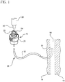
- a vascular access device (also referred to as an extravascular device, intravenous access device, access port, and/or any device attached to or functioning with an extravascular system) 10 is used to introduce a substance via a catheter 12 across the skin 14 and into a blood vessel 16 of a patient 18.
- the vascular access device 10 includes a body 20 with a lumen and a septum 22 placed within the lumen.
- the septum 22 has a slit 24 through which a separate extravascular device 26, such as a syringe, may introduce a substance into the vascular access device 10.
- the device 10 and all structures used in combination therewith may form a larger extravascular system 28.
- a tip 30 of the separate device 26 may be inserted into the device 10 through the slit 24 of the septum 22.
- the tip 30 will serve to communicate fluid through the device 10 and the end 32 of the catheter 12 when the device 10 is in use.
- the two opposing slit 24 surfaces of the septum 22 will separate in opposing lateral directions and will stretch the slit 24 surfaces of the septum 22 in an axial direction, thus increasing the overall height of the septum 22.
- the seal between the device 10 and the tip 30 is rendered more effective.
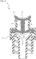
- a vascular access device 10 includes a body 20, a septum 22 at least partially housed within the body 20, at least one gas chamber 34 housed between the body 20 and the septum 22, and a receptacle 36 within the body 20 for receiving gas from the gas chamber 34 as the septum 22 is actuated.
- a vent 38 also housed within the body 20, connects the gas chamber 34 to the receptacle 36.
- the receptacle 36 may be a neighboring gas chamber that is close in proximity to the gas chamber 34.
- the purpose of the receptacle 36 is to increase the total effective volume of the gas chamber 34 by placing the gas chamber 34 in communication with the receptacle 36 by means of the vent 38. By increasing the total effective volume of the gas chamber 34, the septum 22 will be able to function properly.
- the volume of the gas chamber 34 decreases, sending gas through the vent 38 and into the receptacle 36. While the total combined volume decreases during septum actuation and access, the percentage of gas within the volume that is compressed is much smaller in relation to the total combined volume than it would otherwise be if the gas chamber 34 was not connected to any other neighboring gas chamber. Thus, in previous vascular access devices without septum vents, the chamber 34 would reach a compression ratio of greater than 90 to 95 percent, causing only 5 to 10 percent of the total volume of the chamber 34 to remain during septum 22 access.
- the total overall volume of the gas chamber 34, vent 38, and receptacle 36 is much larger than a conventional gas chamber, when the gas chamber 34 is nearly fully compressed, a large amount of volume, i.e., about 40 to 70 percent, remains uncompressed.
- the volume of the neighboring gas chamber or receptacle 36 may be increased in order to further increase the overall volume and reduce the percentage of volume compressed when the gas chamber 34 is collapsed upon septum 22 access.
- the receptacle 36 may reside at any point within the device 10, so long as the receptacle 36 is in communication with the gas chamber 34.
- the septum 22 and other portions of the device 10 may be secured under pressure in order to prevent leakage of fluid within the device or microbial ingress within the device from a surrounding environment.
- a vascular access device 10 includes a body 20 and a septum 22 at least partially housed within the body 20.
- a gas chamber 34 resides between the septum 22 and the body 20.
- the septum 22 includes a bottom disk 40 that is thin enough to cause the bottom disk 40 to balloon and create a receptacle 36 as the septum 22 is actuated and the gas chamber 34 decreases in volume upon insertion of the tip 30 of a separate access device 26.
- the gas chamber 34 is in full volume.
- the volume of the gas chamber 34 is transferred downward into the ballooning portion of the bottom disk 40 of the septum 22.
- the device 10 includes a cavity 42 below the bottom disk 40 of the septum 22.
- the cavity 42 is of sufficient volume to receive the receptacle 36 and simultaneously permit the tip 30 of the separate access device 26 to communicate fluid with the cavity through a fluid transfer channel 44.
- the bottom disk 40 of the septum 22 is thinned and optimized to allow the bottom disk 40 to balloon into the base and chamber 42 of the device 10.
- the septum 22 need not necessarily balloon in order for the volume of the gas chamber 34 to be fully transferred into the receptacle 36, so long as the volume of the cavity 42 is large enough to receive the receptacle 36.
- the volume of the cavity may be increased by either lengthening the cavity 42 or widening the walls of the body 20 surrounding the cavity 42 in a lateral direction 46.
- the bottom disk 40 of the septum 22 may be thinned or otherwise structured or replaced with a material capable of ballooning to a point at which a user will be able to easily access the septum 22 by inserting the tip 30 of a separate access device 26 with minimal force.
- the ballooning bottom disk 40 should be sufficiently resilient in order to provide the force necessary to return the septum 22 to its original position upon retraction of the tip 30 from the septum 22.
- the resiliency of the bottom disk will cause the volume of the receptacle 36 to decrease as the volume of the gas chamber 34 is increased, returning to its original gas chamber 34 position.
- a vascular access device 10 includes a body 20, a septum 22 at least partially housed within the body 20, and at least one gas chamber 34 housed between the septum 22 and the body 20, and an elastomer 48 in communication with the gas chamber 34.
- the gas chamber 34 In its resting state as shown in Figure 5 , the gas chamber 34 resides at maximum volume and the elastomer 48 is not expanded.
- Figure 6 illustrates the functionality of the elastomer 48 upon insertion of the tip 30 of a separate access device 26 into the septum 22.
- the vascular access device 10 of Figure 5 is shown in cross section view with the elastomer 48 expanded, causing an increase in volume within the elastomer.
- the increase in volume within the elastomer is a receptacle 50 for receiving gas from the gas chamber 34.
- the elastomer 48 expands and the receptacle 50 increases in volume as the gas chamber 34 decreases in volume.
- the resilient nature of the elastomer 48 causes the elastomer 48 to contract, consequently causing the gas chamber 34 to increase in volume as the receptacle 50 decreases in volume and the elastomer 48 returns to its original resting position as shown in Figure 5 .
- air may be displaced or otherwise transferred from the gas chamber 34 into a receptacle 50 that is in communication with the gas chamber 34.
- the elastomer 48 and receptacle 50 may be located at any functional or non-functional area of the device 10.
- the elastomer may be placed upon the shoulder of the body 20 as shown in Figure 6A .
Landscapes
- Health & Medical Sciences (AREA)
- Heart & Thoracic Surgery (AREA)
- Pulmonology (AREA)
- Engineering & Computer Science (AREA)
- Anesthesiology (AREA)
- Biomedical Technology (AREA)
- Hematology (AREA)
- Life Sciences & Earth Sciences (AREA)
- Animal Behavior & Ethology (AREA)
- General Health & Medical Sciences (AREA)
- Public Health (AREA)
- Veterinary Medicine (AREA)
- Infusion, Injection, And Reservoir Apparatuses (AREA)
- External Artificial Organs (AREA)
Claims (10)
- Gefäßzugangsvorrichtung, die umfasst:einen Körper (20),ein Septum (22), das zumindest teilweise in dem Körper (20) angeordnet ist, wobei das Septum eine Bodenscheibe (40) aufweist,eine Gaskammer (34), die zwischen dem Körper (20) und dem Septum (22) angeordnet ist, wobei sich das Volumen der Gaskammer (34) beim Einsetzen einer Spitze einer separaten Zugangsvorrichtung verkleinert, undeine Aufnahmeeinrichtung (36) in dem Körper (20) zum Aufnehmen von Gas aus der Gaskammer (34), wenn das Septum (22) betätigt wird, wobei die Aufnahmeeinrichtung eine benachbarte Gaskammer (36) ist,dadurch gekennzeichnet, dasssich die Bodenscheibe (40) aufbläht und die Aufnahmeeinrichtung (36) bildet, wenn das Septum (22) betätigt wird, unddie Gefäßzugangsvorrichtung ferner einen Hohlraum (42) unter der Bodenscheibe (40) des Septums (22) umfasst, wobei der Hohlraum (42) ein ausreichendes Volumen zum Aufnehmen der Aufnahmeeinrichtung (36) aufweist, wobei ein Fluidübertragungskanal (44) verbleibt.
- Medizinische Vorrichtung nach Anspruch 1, bei der die Vorrichtung einen Hohlraum (42) unter dem Septum (22) mit einem ausreichenden Volumen zum Aufnehmen der Aufnahmeeinrichtung (36) aufweist und gleichzeitig ermöglicht, dass eine separate Zugangsvorrichtung mit dem Hohlraum (42) in Fluidverbindung steht.
- Medizinische Vorrichtung nach Anspruch 2, bei der das Septum (22) eine Bodenscheibe (40) aufweist, die dünn genug ist, um zu bewirken, dass sich die Bodenscheibe (40) aufbläht und die Aufnahmeeinrichtung (36) bildet, wenn das Septum (22) betätigt wird, und sich das Volumen der Gaskammer (34) verkleinert.
- Medizinische Vorrichtung nach Anspruch 1, bei der die Aufnahmeeinrichtung (36) ein Elastomer ist, das mit der Gaskammer (34) in Verbindung steht, wobei sich das Elastomer vorzugsweise dehnt und sich das Volumen der Aufnahmeeinrichtung (36) vorzugsweise vergrößert, wenn sich das Volumen der Gaskammer (34) verkleinert.
- Medizinische Vorrichtung nach Anspruch 4, bei der sich das Volumen der Gaskammer (34) vergrößert, wenn sich das Elastomer zusammenzieht, und sich das Volumen der Aufnahmeeinrichtung (36) verkleinert.
- Verfahren zum Weiterleiten von Gas in einer medizinischen Vorrichtung, das umfasst:Bereitstellen einer Gefäßzugangsvorrichtung, wobei die Vorrichtung einen Körper (20), ein Septum (22), das in dem Körper (20) angeordnet ist, wobei das Septum eine Bodenscheibe (40) aufweist, und eine Gaskammer (34) zwischen dem Körper (20) und dem Septum (22) aufweist; undBereitstellen einer Aufnahmeeinrichtung (36) in dem Körper (20), wobei die Aufnahmeeinrichtung eine benachbarte Gaskammer (36) ist;gekennzeichnet durchÜbertragen von Gas zwischen der Gaskammer (34) und der Aufnahmeeinrichtung (36);Aufblähen des Septums (22) zum Bilden der Aufnahmeeinrichtung (36); und Bereitstellen eines Hohlraums, der in der Lage ist, das sich aufblähende Septum aufzunehmen, wobei ein Fluidkanal (44) verbleibt.
- Verfahren nach Anspruch 6, das ferner das Vergrößern des effektiven Gesamtvolumens der Gaskammer (34) durch Platzieren der Gaskammer (34) in Verbindung mit der Aufnahmeeinrichtung (36) umfasst, wobei die Aufnahmeeinrichtung (36) ein Volumen aufweist.
- Verfahren nach Anspruch 6, bei dem die Aufnahmeeinrichtung (36) ein Volumen aufweist, und das ferner das Verringern des Drucks, der zum Komprimieren der Gaskammer erforderlich ist, durch Platzieren der Gaskammer (34) in Verbindung mit dem Volumen der Aufnahmeeinrichtung (36) umfasst.
- Verfahren nach Anspruch 6, das ferner das Aufblähen des Septums (22) zum Bilden der Aufnahmeeinrichtung (36) umfasst und vorzugsweise ferner das Bereitstellen eines Hohlraums (42) umfasst, der in der Lage ist, das sich aufblähende Septum (22) aufzunehmen, und gleichzeitiges Ermöglichen, dass eine separate Zugangsvorrichtung in Fluidverbindung mit dem Hohlraum (42) steht.
- Verfahren nach Anspruch 6, das ferner das Dehnen der Aufnahmeeinrichtung (36), während sich das Volumen der Gaskammer (34) verkleinert, umfasst und/oder ferner das Zusammenziehen der Aufnahmeeinrichtung (36), während sich das Volumen der Gaskammer (34) vergrößert, umfasst.
Applications Claiming Priority (3)
| Application Number | Priority Date | Filing Date | Title |
|---|---|---|---|
| US86411306P | 2006-11-02 | 2006-11-02 | |
| US11/931,597 US8366676B2 (en) | 2006-11-02 | 2007-10-31 | Vascular access device gas displacement |
| PCT/US2007/083367 WO2008057959A2 (en) | 2006-11-02 | 2007-11-01 | Vascular access device gas displacement |
Publications (3)
| Publication Number | Publication Date |
|---|---|
| EP2079409A2 EP2079409A2 (de) | 2009-07-22 |
| EP2079409A4 EP2079409A4 (de) | 2014-04-09 |
| EP2079409B1 true EP2079409B1 (de) | 2018-08-01 |
Family
ID=39360607
Family Applications (1)
| Application Number | Title | Priority Date | Filing Date |
|---|---|---|---|
| EP07844823.0A Active EP2079409B1 (de) | 2006-11-02 | 2007-11-01 | Gasweiterleitung in einer gefässzugangsvorrichtung |
Country Status (8)
| Country | Link |
|---|---|
| US (1) | US8366676B2 (de) |
| EP (1) | EP2079409B1 (de) |
| JP (1) | JP5264753B2 (de) |
| CN (1) | CN101583390B (de) |
| AU (1) | AU2007317454B2 (de) |
| BR (1) | BRPI0718045B8 (de) |
| ES (1) | ES2692861T3 (de) |
| WO (1) | WO2008057959A2 (de) |
Families Citing this family (22)
| Publication number | Priority date | Publication date | Assignee | Title |
|---|---|---|---|---|
| US20060161115A1 (en) | 2004-11-05 | 2006-07-20 | Fangrow Thomas F | Soft-grip medical connector |
| ES2362449T3 (es) | 2006-10-25 | 2011-07-05 | Icu Medical, Inc. | Conector médico. |
| US9168366B2 (en) | 2008-12-19 | 2015-10-27 | Icu Medical, Inc. | Medical connector with closeable luer connector |
| US8454579B2 (en) | 2009-03-25 | 2013-06-04 | Icu Medical, Inc. | Medical connector with automatic valves and volume regulator |
| US8323249B2 (en) | 2009-08-14 | 2012-12-04 | The Regents Of The University Of Michigan | Integrated vascular delivery system |
| USD644731S1 (en) | 2010-03-23 | 2011-09-06 | Icu Medical, Inc. | Medical connector |
| US8758306B2 (en) | 2010-05-17 | 2014-06-24 | Icu Medical, Inc. | Medical connectors and methods of use |
| WO2011146772A1 (en) | 2010-05-19 | 2011-11-24 | Tangent Medical Technologies Llc | Safety needle system operable with a medical device |
| US8771230B2 (en) | 2010-05-19 | 2014-07-08 | Tangent Medical Technologies, Llc | Integrated vascular delivery system |
| WO2012106613A1 (en) * | 2011-02-04 | 2012-08-09 | Merit Medical Systems, Inc. | Gas adaptor and method of use |
| ES2664517T3 (es) | 2011-09-09 | 2018-04-19 | Icu Medical, Inc. | Conectores médicos con interfaces de acoplamiento resistentes a fluidos |
| AU2013342123B2 (en) | 2012-11-12 | 2018-08-02 | Icu Medical, Inc. | Medical connector |
| WO2014149566A1 (en) | 2013-03-15 | 2014-09-25 | Icu Medical , Inc. | Medical connector |
| EP3079739B1 (de) | 2013-12-11 | 2023-02-22 | ICU Medical, Inc. | Rückschlagventil |
| AU2015214400B2 (en) | 2014-02-04 | 2019-10-03 | Icu Medical, Inc. | Self-priming systems and methods |
| US20150337974A1 (en) * | 2014-05-23 | 2015-11-26 | Charles Allen | Inflation valve cap apparatus and method |
| US20150337975A1 (en) * | 2014-05-23 | 2015-11-26 | Charles Allen | Inflation valve cap apparatus and method |
| US10436336B2 (en) * | 2014-11-13 | 2019-10-08 | Charles Allen | Cap with valve for inflation |
| USD793551S1 (en) | 2014-12-03 | 2017-08-01 | Icu Medical, Inc. | Fluid manifold |
| USD786427S1 (en) | 2014-12-03 | 2017-05-09 | Icu Medical, Inc. | Fluid manifold |
| EP4617198A3 (de) * | 2020-01-24 | 2025-12-10 | Boehringer Ingelheim Vetmedica GmbH | Verbindungsanordnung, verbindungssystem, behälter und behältersystem |
| USD1105422S1 (en) | 2024-02-09 | 2025-12-09 | Icu Medical, Inc. | Medical connector cover |
Family Cites Families (35)
| Publication number | Priority date | Publication date | Assignee | Title |
|---|---|---|---|---|
| US4765588A (en) * | 1986-08-18 | 1988-08-23 | Vernay Laboratories, Inc. | Check valve for use with a syringe |
| GB8627808D0 (en) * | 1986-11-20 | 1986-12-17 | Cox J A | Sampling liquids from human/animal body |
| US5251873B1 (en) * | 1992-06-04 | 1995-05-02 | Vernay Laboratories | Medical coupling site. |
| US5295658A (en) * | 1987-04-27 | 1994-03-22 | Vernay Laboratories, Inc. | Medical coupling site including slit reinforcing members |
| GB9103122D0 (en) * | 1991-02-14 | 1991-04-03 | Wallace Ltd H G | Resealable sampling port |
| US5501426A (en) * | 1992-06-04 | 1996-03-26 | Vernay Laboratories, Inc. | Medical coupling site valve body |
| US5533708A (en) * | 1992-06-04 | 1996-07-09 | Vernay Laboratories, Inc. | Medical coupling site valve body |
| US6068011A (en) * | 1993-10-13 | 2000-05-30 | Paradis; Joseph R. | Control of fluid flow |
| WO1995015195A1 (en) * | 1993-11-30 | 1995-06-08 | Medex, Inc. | Plastic needleless valve housing for standard male luer locks |
| US5549651A (en) * | 1994-05-25 | 1996-08-27 | Lynn; Lawrence A. | Luer-receiving medical valve and fluid transfer method |
| US7033339B1 (en) * | 1998-05-29 | 2006-04-25 | Becton Dickinson And Company (Part Interest) | Self sealing luer receiving stopcock |
| US5474544A (en) * | 1994-05-25 | 1995-12-12 | Lynn; Lawrence A. | Luer-receiving medical valve |
| US5820601A (en) * | 1994-06-20 | 1998-10-13 | Critical Device Corporation | Needleless injection site |
| US7789864B2 (en) * | 1996-11-18 | 2010-09-07 | Nypro Inc. | Luer-activated valve |
| US6050978A (en) * | 1997-05-09 | 2000-04-18 | Becton Dickinson And Company | Needleless valve connector |
| US5957898A (en) * | 1997-05-20 | 1999-09-28 | Baxter International Inc. | Needleless connector |
| EP0923391B1 (de) * | 1997-05-20 | 2006-08-09 | Baxter International Inc. | Nadelloses kupplungsstück |
| US6029946A (en) * | 1997-09-15 | 2000-02-29 | Tiva Medical Inc. | Needleless valve |
| DE69940669D1 (de) * | 1998-05-29 | 2009-05-14 | Lawrence A Lynn | Lueradapter und Methode zum Flüssigkeitstransfer |
| US6706022B1 (en) * | 1999-07-27 | 2004-03-16 | Alaris Medical Systems, Inc. | Needleless medical connector with expandable valve mechanism |
| US6695817B1 (en) * | 2000-07-11 | 2004-02-24 | Icu Medical, Inc. | Medical valve with positive flow characteristics |
| WO2002034326A2 (en) * | 2000-10-23 | 2002-05-02 | Nypro, Inc. | Anti-drawback medical valve |
| US6595964B2 (en) * | 2000-12-22 | 2003-07-22 | Baxter International Inc. | Luer activated thread coupler |
| BRPI0206669B8 (pt) * | 2001-01-24 | 2021-06-22 | Becton Dickinson Co | dispositivo médico compreendendo revestimento lubrificante |
| JP2005500142A (ja) * | 2001-08-22 | 2005-01-06 | ナイプロ・インク | 拡張部材を備える医療用弁 |
| WO2003018105A1 (en) * | 2001-08-23 | 2003-03-06 | Occupational & Medical Innovations Ltd | A valve for use with a syringe and which prevents backflow |
| US7037302B2 (en) * | 2001-09-07 | 2006-05-02 | Patricia B. Vaillancourt, legal representative | Positive flow needleless connector |
| US6802490B2 (en) * | 2001-11-29 | 2004-10-12 | Alaris Medical Systems, Inc. | Needle free medical connector with expanded valve mechanism and method of fluid flow control |
| US6908459B2 (en) * | 2001-12-07 | 2005-06-21 | Becton, Dickinson And Company | Needleless luer access connector |
| US6651956B2 (en) * | 2002-01-31 | 2003-11-25 | Halkey-Roberts Corporation | Slit-type swabable valve |
| US7244249B2 (en) * | 2002-05-08 | 2007-07-17 | Cardinal Health 303, Inc. | Needle-free medical connector with expandable valve mechanism and method of fluid flow control |
| US7306579B2 (en) * | 2002-08-12 | 2007-12-11 | Jms Co., Ltd. | Needleless port |
| US20040073171A1 (en) * | 2002-10-10 | 2004-04-15 | Rogers Bobby E. | Needle-free valve and catheter assembly |
| US20070225635A1 (en) * | 2006-03-16 | 2007-09-27 | Lynn Lawrence A | Mechanically anti-infective access system and method |
| US7981090B2 (en) * | 2006-10-18 | 2011-07-19 | Baxter International Inc. | Luer activated device |
-
2007
- 2007-10-31 US US11/931,597 patent/US8366676B2/en active Active
- 2007-11-01 ES ES07844823.0T patent/ES2692861T3/es active Active
- 2007-11-01 AU AU2007317454A patent/AU2007317454B2/en active Active
- 2007-11-01 CN CN2007800406973A patent/CN101583390B/zh active Active
- 2007-11-01 JP JP2009536398A patent/JP5264753B2/ja active Active
- 2007-11-01 BR BRPI0718045A patent/BRPI0718045B8/pt active IP Right Grant
- 2007-11-01 EP EP07844823.0A patent/EP2079409B1/de active Active
- 2007-11-01 WO PCT/US2007/083367 patent/WO2008057959A2/en not_active Ceased
Non-Patent Citations (1)
| Title |
|---|
| None * |
Also Published As
| Publication number | Publication date |
|---|---|
| AU2007317454A1 (en) | 2008-05-15 |
| US8366676B2 (en) | 2013-02-05 |
| US20080108973A1 (en) | 2008-05-08 |
| WO2008057959A9 (en) | 2009-07-16 |
| CN101583390B (zh) | 2012-07-04 |
| ES2692861T3 (es) | 2018-12-05 |
| JP2010508987A (ja) | 2010-03-25 |
| BRPI0718045A2 (pt) | 2013-11-12 |
| BRPI0718045B1 (pt) | 2018-12-04 |
| WO2008057959A2 (en) | 2008-05-15 |
| EP2079409A4 (de) | 2014-04-09 |
| CN101583390A (zh) | 2009-11-18 |
| BRPI0718045B8 (pt) | 2021-06-22 |
| JP5264753B2 (ja) | 2013-08-14 |
| AU2007317454B2 (en) | 2013-03-28 |
| EP2079409A2 (de) | 2009-07-22 |
Similar Documents
| Publication | Publication Date | Title |
|---|---|---|
| US8366676B2 (en) | Vascular access device gas displacement | |
| EP3207955B1 (de) | Austausch der kammer einer gefässzugangsvorrichtung | |
| EP2079499B1 (de) | Entlüftung der kammer einer gefässzugangseinrichtung | |
| US12194249B2 (en) | Multiple-use intravenous catheter assembly septum and septum actuator | |
| EP0923391B1 (de) | Nadelloses kupplungsstück | |
| US20080027415A1 (en) | Vascular access device volume displacement | |
| CN220110187U (zh) | 外周静脉内导管组件 | |
| CN120919487A (zh) | 具有改进的背压性能和防泄漏的导管组件近端口连接器 |
Legal Events
| Date | Code | Title | Description |
|---|---|---|---|
| PUAI | Public reference made under article 153(3) epc to a published international application that has entered the european phase |
Free format text: ORIGINAL CODE: 0009012 |
|
| 17P | Request for examination filed |
Effective date: 20090507 |
|
| AK | Designated contracting states |
Kind code of ref document: A2 Designated state(s): AT BE BG CH CY CZ DE DK EE ES FI FR GB GR HU IE IS IT LI LT LU LV MC MT NL PL PT RO SE SI SK TR |
|
| R17D | Deferred search report published (corrected) |
Effective date: 20090716 |
|
| DAX | Request for extension of the european patent (deleted) | ||
| REG | Reference to a national code |
Ref country code: DE Ref legal event code: R079 Ref document number: 602007055596 Country of ref document: DE Free format text: PREVIOUS MAIN CLASS: A61F0005440000 Ipc: A61M0039260000 |
|
| A4 | Supplementary search report drawn up and despatched |
Effective date: 20140312 |
|
| RIC1 | Information provided on ipc code assigned before grant |
Ipc: A61M 39/04 20060101ALI20140306BHEP Ipc: A61M 39/26 20060101AFI20140306BHEP |
|
| RAP1 | Party data changed (applicant data changed or rights of an application transferred) |
Owner name: BECTON, DICKINSON AND COMPANY |
|
| STAA | Information on the status of an ep patent application or granted ep patent |
Free format text: STATUS: EXAMINATION IS IN PROGRESS |
|
| 17Q | First examination report despatched |
Effective date: 20170608 |
|
| GRAP | Despatch of communication of intention to grant a patent |
Free format text: ORIGINAL CODE: EPIDOSNIGR1 |
|
| STAA | Information on the status of an ep patent application or granted ep patent |
Free format text: STATUS: GRANT OF PATENT IS INTENDED |
|
| INTG | Intention to grant announced |
Effective date: 20180216 |
|
| INTG | Intention to grant announced |
Effective date: 20180216 |
|
| GRAS | Grant fee paid |
Free format text: ORIGINAL CODE: EPIDOSNIGR3 |
|
| GRAA | (expected) grant |
Free format text: ORIGINAL CODE: 0009210 |
|
| STAA | Information on the status of an ep patent application or granted ep patent |
Free format text: STATUS: THE PATENT HAS BEEN GRANTED |
|
| AK | Designated contracting states |
Kind code of ref document: B1 Designated state(s): AT BE BG CH CY CZ DE DK EE ES FI FR GB GR HU IE IS IT LI LT LU LV MC MT NL PL PT RO SE SI SK TR |
|
| REG | Reference to a national code |
Ref country code: GB Ref legal event code: FG4D |
|
| REG | Reference to a national code |
Ref country code: CH Ref legal event code: EP Ref country code: AT Ref legal event code: REF Ref document number: 1023596 Country of ref document: AT Kind code of ref document: T Effective date: 20180815 |
|
| REG | Reference to a national code |
Ref country code: IE Ref legal event code: FG4D |
|
| REG | Reference to a national code |
Ref country code: DE Ref legal event code: R096 Ref document number: 602007055596 Country of ref document: DE |
|
| REG | Reference to a national code |
Ref country code: FR Ref legal event code: PLFP Year of fee payment: 12 |
|
| REG | Reference to a national code |
Ref country code: ES Ref legal event code: FG2A Ref document number: 2692861 Country of ref document: ES Kind code of ref document: T3 Effective date: 20181205 Ref country code: NL Ref legal event code: MP Effective date: 20180801 |
|
| REG | Reference to a national code |
Ref country code: LT Ref legal event code: MG4D |
|
| REG | Reference to a national code |
Ref country code: AT Ref legal event code: MK05 Ref document number: 1023596 Country of ref document: AT Kind code of ref document: T Effective date: 20180801 |
|
| PG25 | Lapsed in a contracting state [announced via postgrant information from national office to epo] |
Ref country code: LT Free format text: LAPSE BECAUSE OF FAILURE TO SUBMIT A TRANSLATION OF THE DESCRIPTION OR TO PAY THE FEE WITHIN THE PRESCRIBED TIME-LIMIT Effective date: 20180801 Ref country code: AT Free format text: LAPSE BECAUSE OF FAILURE TO SUBMIT A TRANSLATION OF THE DESCRIPTION OR TO PAY THE FEE WITHIN THE PRESCRIBED TIME-LIMIT Effective date: 20180801 Ref country code: PL Free format text: LAPSE BECAUSE OF FAILURE TO SUBMIT A TRANSLATION OF THE DESCRIPTION OR TO PAY THE FEE WITHIN THE PRESCRIBED TIME-LIMIT Effective date: 20180801 Ref country code: IS Free format text: LAPSE BECAUSE OF FAILURE TO SUBMIT A TRANSLATION OF THE DESCRIPTION OR TO PAY THE FEE WITHIN THE PRESCRIBED TIME-LIMIT Effective date: 20181201 Ref country code: NL Free format text: LAPSE BECAUSE OF FAILURE TO SUBMIT A TRANSLATION OF THE DESCRIPTION OR TO PAY THE FEE WITHIN THE PRESCRIBED TIME-LIMIT Effective date: 20180801 Ref country code: SE Free format text: LAPSE BECAUSE OF FAILURE TO SUBMIT A TRANSLATION OF THE DESCRIPTION OR TO PAY THE FEE WITHIN THE PRESCRIBED TIME-LIMIT Effective date: 20180801 Ref country code: BG Free format text: LAPSE BECAUSE OF FAILURE TO SUBMIT A TRANSLATION OF THE DESCRIPTION OR TO PAY THE FEE WITHIN THE PRESCRIBED TIME-LIMIT Effective date: 20181101 Ref country code: FI Free format text: LAPSE BECAUSE OF FAILURE TO SUBMIT A TRANSLATION OF THE DESCRIPTION OR TO PAY THE FEE WITHIN THE PRESCRIBED TIME-LIMIT Effective date: 20180801 Ref country code: GR Free format text: LAPSE BECAUSE OF FAILURE TO SUBMIT A TRANSLATION OF THE DESCRIPTION OR TO PAY THE FEE WITHIN THE PRESCRIBED TIME-LIMIT Effective date: 20181102 |
|
| PG25 | Lapsed in a contracting state [announced via postgrant information from national office to epo] |
Ref country code: LV Free format text: LAPSE BECAUSE OF FAILURE TO SUBMIT A TRANSLATION OF THE DESCRIPTION OR TO PAY THE FEE WITHIN THE PRESCRIBED TIME-LIMIT Effective date: 20180801 |
|
| PG25 | Lapsed in a contracting state [announced via postgrant information from national office to epo] |
Ref country code: EE Free format text: LAPSE BECAUSE OF FAILURE TO SUBMIT A TRANSLATION OF THE DESCRIPTION OR TO PAY THE FEE WITHIN THE PRESCRIBED TIME-LIMIT Effective date: 20180801 Ref country code: RO Free format text: LAPSE BECAUSE OF FAILURE TO SUBMIT A TRANSLATION OF THE DESCRIPTION OR TO PAY THE FEE WITHIN THE PRESCRIBED TIME-LIMIT Effective date: 20180801 Ref country code: CZ Free format text: LAPSE BECAUSE OF FAILURE TO SUBMIT A TRANSLATION OF THE DESCRIPTION OR TO PAY THE FEE WITHIN THE PRESCRIBED TIME-LIMIT Effective date: 20180801 |
|
| REG | Reference to a national code |
Ref country code: DE Ref legal event code: R097 Ref document number: 602007055596 Country of ref document: DE |
|
| PG25 | Lapsed in a contracting state [announced via postgrant information from national office to epo] |
Ref country code: SK Free format text: LAPSE BECAUSE OF FAILURE TO SUBMIT A TRANSLATION OF THE DESCRIPTION OR TO PAY THE FEE WITHIN THE PRESCRIBED TIME-LIMIT Effective date: 20180801 Ref country code: DK Free format text: LAPSE BECAUSE OF FAILURE TO SUBMIT A TRANSLATION OF THE DESCRIPTION OR TO PAY THE FEE WITHIN THE PRESCRIBED TIME-LIMIT Effective date: 20180801 |
|
| PLBE | No opposition filed within time limit |
Free format text: ORIGINAL CODE: 0009261 |
|
| STAA | Information on the status of an ep patent application or granted ep patent |
Free format text: STATUS: NO OPPOSITION FILED WITHIN TIME LIMIT |
|
| REG | Reference to a national code |
Ref country code: CH Ref legal event code: PL |
|
| 26N | No opposition filed |
Effective date: 20190503 |
|
| PG25 | Lapsed in a contracting state [announced via postgrant information from national office to epo] |
Ref country code: LU Free format text: LAPSE BECAUSE OF NON-PAYMENT OF DUE FEES Effective date: 20181101 Ref country code: MC Free format text: LAPSE BECAUSE OF FAILURE TO SUBMIT A TRANSLATION OF THE DESCRIPTION OR TO PAY THE FEE WITHIN THE PRESCRIBED TIME-LIMIT Effective date: 20180801 |
|
| REG | Reference to a national code |
Ref country code: IE Ref legal event code: MM4A |
|
| PG25 | Lapsed in a contracting state [announced via postgrant information from national office to epo] |
Ref country code: SI Free format text: LAPSE BECAUSE OF FAILURE TO SUBMIT A TRANSLATION OF THE DESCRIPTION OR TO PAY THE FEE WITHIN THE PRESCRIBED TIME-LIMIT Effective date: 20180801 Ref country code: CH Free format text: LAPSE BECAUSE OF NON-PAYMENT OF DUE FEES Effective date: 20181130 Ref country code: LI Free format text: LAPSE BECAUSE OF NON-PAYMENT OF DUE FEES Effective date: 20181130 |
|
| PG25 | Lapsed in a contracting state [announced via postgrant information from national office to epo] |
Ref country code: IE Free format text: LAPSE BECAUSE OF NON-PAYMENT OF DUE FEES Effective date: 20181101 |
|
| PG25 | Lapsed in a contracting state [announced via postgrant information from national office to epo] |
Ref country code: MT Free format text: LAPSE BECAUSE OF NON-PAYMENT OF DUE FEES Effective date: 20181101 |
|
| PG25 | Lapsed in a contracting state [announced via postgrant information from national office to epo] |
Ref country code: TR Free format text: LAPSE BECAUSE OF FAILURE TO SUBMIT A TRANSLATION OF THE DESCRIPTION OR TO PAY THE FEE WITHIN THE PRESCRIBED TIME-LIMIT Effective date: 20180801 |
|
| PG25 | Lapsed in a contracting state [announced via postgrant information from national office to epo] |
Ref country code: PT Free format text: LAPSE BECAUSE OF FAILURE TO SUBMIT A TRANSLATION OF THE DESCRIPTION OR TO PAY THE FEE WITHIN THE PRESCRIBED TIME-LIMIT Effective date: 20180801 |
|
| PG25 | Lapsed in a contracting state [announced via postgrant information from national office to epo] |
Ref country code: HU Free format text: LAPSE BECAUSE OF FAILURE TO SUBMIT A TRANSLATION OF THE DESCRIPTION OR TO PAY THE FEE WITHIN THE PRESCRIBED TIME-LIMIT; INVALID AB INITIO Effective date: 20071101 Ref country code: CY Free format text: LAPSE BECAUSE OF FAILURE TO SUBMIT A TRANSLATION OF THE DESCRIPTION OR TO PAY THE FEE WITHIN THE PRESCRIBED TIME-LIMIT Effective date: 20180801 |
|
| PGFP | Annual fee paid to national office [announced via postgrant information from national office to epo] |
Ref country code: DE Payment date: 20241022 Year of fee payment: 18 |
|
| PGFP | Annual fee paid to national office [announced via postgrant information from national office to epo] |
Ref country code: GB Payment date: 20251023 Year of fee payment: 19 |
|
| PGFP | Annual fee paid to national office [announced via postgrant information from national office to epo] |
Ref country code: IT Payment date: 20251022 Year of fee payment: 19 |
|
| PGFP | Annual fee paid to national office [announced via postgrant information from national office to epo] |
Ref country code: FR Payment date: 20251023 Year of fee payment: 19 |
|
| PGFP | Annual fee paid to national office [announced via postgrant information from national office to epo] |
Ref country code: BE Payment date: 20251022 Year of fee payment: 19 |
|
| PGFP | Annual fee paid to national office [announced via postgrant information from national office to epo] |
Ref country code: ES Payment date: 20251201 Year of fee payment: 19 |