EP2079948B1 - Vorrichtung zur öffnung/schliessung von ventilen oder ähnlichem - Google Patents
Vorrichtung zur öffnung/schliessung von ventilen oder ähnlichem Download PDFInfo
- Publication number
- EP2079948B1 EP2079948B1 EP07848135.5A EP07848135A EP2079948B1 EP 2079948 B1 EP2079948 B1 EP 2079948B1 EP 07848135 A EP07848135 A EP 07848135A EP 2079948 B1 EP2079948 B1 EP 2079948B1
- Authority
- EP
- European Patent Office
- Prior art keywords
- valve
- drive wheel
- pins
- handwheel
- collar
- Prior art date
- Legal status (The legal status is an assumption and is not a legal conclusion. Google has not performed a legal analysis and makes no representation as to the accuracy of the status listed.)
- Not-in-force
Links
Images
Classifications
-
- F—MECHANICAL ENGINEERING; LIGHTING; HEATING; WEAPONS; BLASTING
- F16—ENGINEERING ELEMENTS AND UNITS; GENERAL MEASURES FOR PRODUCING AND MAINTAINING EFFECTIVE FUNCTIONING OF MACHINES OR INSTALLATIONS; THERMAL INSULATION IN GENERAL
- F16K—VALVES; TAPS; COCKS; ACTUATING-FLOATS; DEVICES FOR VENTING OR AERATING
- F16K31/00—Actuating devices; Operating means; Releasing devices
- F16K31/44—Mechanical actuating means
-
- F—MECHANICAL ENGINEERING; LIGHTING; HEATING; WEAPONS; BLASTING
- F16—ENGINEERING ELEMENTS AND UNITS; GENERAL MEASURES FOR PRODUCING AND MAINTAINING EFFECTIVE FUNCTIONING OF MACHINES OR INSTALLATIONS; THERMAL INSULATION IN GENERAL
- F16K—VALVES; TAPS; COCKS; ACTUATING-FLOATS; DEVICES FOR VENTING OR AERATING
- F16K31/00—Actuating devices; Operating means; Releasing devices
- F16K31/02—Actuating devices; Operating means; Releasing devices electric; magnetic
- F16K31/04—Actuating devices; Operating means; Releasing devices electric; magnetic using a motor
- F16K31/05—Actuating devices; Operating means; Releasing devices electric; magnetic using a motor specially adapted for operating hand-operated valves or for combined motor and hand operation
-
- B—PERFORMING OPERATIONS; TRANSPORTING
- B25—HAND TOOLS; PORTABLE POWER-DRIVEN TOOLS; MANIPULATORS
- B25B—TOOLS OR BENCH DEVICES NOT OTHERWISE PROVIDED FOR, FOR FASTENING, CONNECTING, DISENGAGING, OR HOLDING
- B25B19/00—Impact wrenches or screwdrivers
-
- F—MECHANICAL ENGINEERING; LIGHTING; HEATING; WEAPONS; BLASTING
- F16—ENGINEERING ELEMENTS AND UNITS; GENERAL MEASURES FOR PRODUCING AND MAINTAINING EFFECTIVE FUNCTIONING OF MACHINES OR INSTALLATIONS; THERMAL INSULATION IN GENERAL
- F16K—VALVES; TAPS; COCKS; ACTUATING-FLOATS; DEVICES FOR VENTING OR AERATING
- F16K31/00—Actuating devices; Operating means; Releasing devices
- F16K31/12—Actuating devices; Operating means; Releasing devices actuated by fluid
- F16K31/14—Actuating devices; Operating means; Releasing devices actuated by fluid for mounting on, or in combination with, hand-actuated valves
-
- F—MECHANICAL ENGINEERING; LIGHTING; HEATING; WEAPONS; BLASTING
- F16—ENGINEERING ELEMENTS AND UNITS; GENERAL MEASURES FOR PRODUCING AND MAINTAINING EFFECTIVE FUNCTIONING OF MACHINES OR INSTALLATIONS; THERMAL INSULATION IN GENERAL
- F16K—VALVES; TAPS; COCKS; ACTUATING-FLOATS; DEVICES FOR VENTING OR AERATING
- F16K31/00—Actuating devices; Operating means; Releasing devices
- F16K31/12—Actuating devices; Operating means; Releasing devices actuated by fluid
- F16K31/16—Actuating devices; Operating means; Releasing devices actuated by fluid with a mechanism, other than pulling-or pushing-rod, between fluid motor and closure member
Definitions
- the present invention relates to a device for opening or closing valves or similar.
- Manually-operated valves are of very many different types and very many size classes. The smallest control very small flows, whereas in various production plants really massive valves are used, the operation of which demands work requiring great strength, especially if the valves are used relatively infrequently, or the process conditions are such that they may jam shut, and they cannot be closed/opened easily with the strength of one man.
- valves In larger production plants, there may be hundreds of valves, so that it is easy to understand that during extensive operations there is a great deal of work in closing and opening valves. Particularly if valves are only used, for example, during annual service or longer breaks in production, there may be numerous valves that have jammed shut and therefore require a great deal of extra work. Turning the valve is work demanding physical strength, but it is also work associated with a considerable risk of causing various stress injuries etc. Strong torsional movements often lead to sprains of some degree and similar injuries. In addition, these operations take much time, which is away from productive work.
- a quite common valve construction is a so-called slide valve, in which the rotation of a handwheel causes the valve spindle to rise and fall, when the slide attached to it correspondingly opens and closes the flow channel. Between the spindle and the handwheel there is a threaded joint, through which a linear movement is transmitted to the spindle when the handwheel is rotated.
- the diameter of the handwheel can be in the order of even a metre. While this of course provides plenty of force for the rotation, nevertheless the force is often too little to perform the work smoothly and correspondingly the work takes place more slowly.
- a device for opening and closing valves is disclosed.
- the device may be connected to a valve and comprises a rotatable coupler connectable to a handwheel on the valve using bolts and nuts.
- a retrofittable electric valve operating mechanism which can be attached to a manual valve while allowing the manual feature to be utilized.
- a valve handle engaging member on the operating mechanism is provided with elongate tongs designed to engage valve handles of various types.
- the present invention is intended to create a device for opening/closing valves, the suitability of which device for different types of valve is ensured and which can be used where suitable operating power, particularly compressed air can be found.
- the construction of the device according to the invention is designed to take account of both usability and work safety. At the same time, the device is nevertheless simple and economical to manufacture.
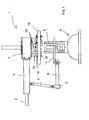
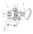
- the main components of the device 1 are the following: An inlet connection 2 to bring operating power, mainly compressed air, to the device 1.
- an inlet connection there could be, for example, an electrical connection for operating the device with the aid of an electric motor.
- the device can typically include an arm component 3 of a suitable length.
- a suitable operating switch is located in a practical place, especially in connection with the arm 3.
- the actual torsion head is marked with the reference number 4.
- arms 5 and 6 are used in the device according to the invention, of which at the end of the latter there is an attachment element 7, which is set to rest on the valve body, in such a way that the valve body supports it between or around its components.
- the distance between the components of the attachment element can be adjusted to be suitable for different constructions and can be locked in their positions.
- the arm 6 is preferably of an adjustable length, for example, in such a way that the arm 6 runs through a loop or eye 5' at the end of the arm 5 in such a way that it slides and can be locked in the desired position. It is obvious that there is a numerous group of adjustable arm constructions, so that the most appropriate of them is selected for use in connection with the invention. By means of this arrangement, manual control of the torsional forces is unnecessary, though when handling valves in normal conditions, which they do not jam badly, use of this arrangement is not needed.
- the operating power for example a pressure medium
- the operating power is brought from the connector 2 to the motor or similar creating a rotation motion in the torsion head 4, and which produces torque, which is transmitted to the shaft of the torsion head.
- Rotation takes place alternatively clockwise or counter-clockwise, depending on whether it is wished to use the device for opening or closing.
- the valve itself can be formed of a valve body 8, a valve spindle 9, and a handwheel 10.
- the structures can vary a great deal, the problems described above being particularly caused by variations in the construction of the handwheel.
- the handwheel 10 there can be two or more spokes, the shape of which can vary, so that according to the present invention the intention is to create a device model that will fit all constructions. Because, as shown in the figures, the spindle 9 often rises above the handwheel 10 when opening, the device must adapt to this construction too.
- the valve as such naturally does not belong to the scope of protection of the present invention.
- the torsion head 4 is formed of a body and a rotating totality mounted on it by bearings, which is operated by the operating force transmitted to it from the drive machine.
- the actual rotation mechanism is not described in greater detail here, because rotating pneumatic tools, for example, embody entirely conventional technology. Most usually the rotational mechanisms are based on interlocking gear wheels.
- the torsion head is ring-shaped, so that the valve spindle 9 can be fitted through the opening 11 remaining in the centre of the torsion head 4.
- the opening 11 is sufficiently wide for any spindle 9 whatever in normal use to fit through it freely.
- a hollow shaft 12 to which is connected an essentially discoid component 14 with a hole concentric with the shaft and which hereinafter is referred to an the drive wheel, runs through the torsion head 4.
- a desired number of collars 13 are, in turn, attached to the upper side of the discoid component 14.
- the collar-pin combinations 13, 15 rotate along with the discoid drive wheel 14, when the shaft 12 rotates it.
- the device according to the invention fits any spoke distribution whatever that may be in the handwheel 10.
- the pins that coincide with the spokes of the handwheel retract. However, those that coincide with a free space remain protruding and can press against the spoke of the handwheel to receive the lateral torsional forces acting on them during rotation.
- the pins 15 are further supported in the direction of the torsional force on the drive wheel 14, penetrating its openings.
- Reference number 16 in the figures marks the means, with the aid of which it is ensured that the device according to the invention remains in place, in such a way that the forks, pivoted at one end around a pivot pin 17, place their ends around the spoke, thus preventing the device from lifting off the during operation.
- the forks of the means 16 operate together, in which case they rotate around the pivot pin 17 in a symmetrical manner, being connected to each other, typically by gearing.
- the means 16 to be attached to the edge of the drive wheel 14 in such a way that they can be slid along the outer edge of the disc to the desired position, which ensures that the means 16 can be moved precisely to the location of a spoke of the hand wheel of the valve and locked around it.
- the number of the means 16 can be selected as desired, generally they are a few.
- the means 16 can also be constructed to be detachable and to only be set in place when required.
- the components 16 can be locked to the ring, in which case they can also be used in addition to/in place of the pins to receive the torsional force.
- the device also operates excellently as a general-purpose device, for example, with roughly the pin density shown in the figures. The number is chosen according to the application if the device is made for a specific application, in which the type of valve is known.
- the components for improving the control of the total device 1 which are marked in the figures with the reference numbers 5, 6 and 7, are optional. They are only one example of the means that can be used, if such are needed at all. There are other alternatives too. The same also applies to the means 16.
- the operation of the embodiment is as follows.
- the device is connected by a suitable connector, for example, to a network supplying compressed aid, or in the case of an electrically powered device to the electricity network.
- the torsion head 4 is slid around the valve spindle 9 and the device laid against the handwheel 10.
- the pins 15 coinciding with the spokes of the handwheel then retract while the others settle into the spaces between the spokes.
- the means 16 are attached if necessary, as are the support arms 5, 6 and 7.
- the direction of rotation of the device is selected, i.e. the valve closing or opening direction and rotation is started for as long as needed to achieve the desired degree of opening or closing. After this, the device is detached from the valve.
- the device according to the invention is also highly suitable for opening and closing valves, in which the spindle does not rise above the plane of the torsion wheel, but, as stated, the invention particularly permits the opening and closing of valves, in which the spindle rises above the torsion wheel.
- the diameter of the drive wheel 14 and also the location and the number of the pin/collar combinations 13, 15 on the drive wheel are defined case-specifically, but in the basic construction preferably in such a way that the construction will suit most valve constructions.
- the pins 15 may be in a retracted condition inside the collar-like components 13, wherefrom they can be pushed out for connecting into the handwheel 10 of the valve for instance pneumatically. Those pins which are located just above the spokes of the handwheel cannot, naturally, be pushed out and they remain inside the collar-like components. Those pins, on the other hand, which are located between the spokes will be pushed out. It is also possible that the pins can be retracted for instance pneumatically after the use.
Landscapes
- Engineering & Computer Science (AREA)
- General Engineering & Computer Science (AREA)
- Mechanical Engineering (AREA)
- Mechanically-Actuated Valves (AREA)
Claims (8)
- Vorrichtung zum Öffnen und Schließen von Ventilen o. ä., wobei die Vorrichtung (1) geeignet ist, mit einem Ventil in der Bediensituation verbunden zu sein, und eine Drehbewegung erzeugt, wobei die Vorrichtung (1) einen Torsionskopf (4) mit einem drehbaren Antriebsrad (14) aufweist, das mit einem Handrad (10) des Ventils verbunden sein kann, wobei mehrere Stifte (15) im Antriebsrad (14) einwärts und auswärts beweglich sind, dadurch gekennzeichnet, dass die Stifte (15) in kragenartigen Komponenten (13) angeordnet sind, die am Antriebsrad (14) befestigt sind, wobei in der Bediensituation:- die Stifte (15) geeignet sind, sich in die kragenartigen Komponenten (13) gegen eine Federkraft oder eine pneumatische Kraft zurückzuziehen, wenn sie auf ein Hindernis stoßen, z. B. eine Speiche des Handrads (10);- oder die Stifte (15) geeignet sind, aus den kragenartigen Komponenten (13) in einem im Wesentlichen freien Raum zum Verbinden mit dem Handrad (10) des Ventils ausgeschoben zu werden, wogegen die über den Speichen des Handrads (10) liegenden Stifte (15) nicht ausgeschoben werden können und innerhalb der kragenartigen Komponenten bleiben.
- Vorrichtung nach Anspruch 1, dadurch gekennzeichnet, dass die kragenartigen Komponenten am Antriebsrad (14) im Wesentlichen in rechten Winkeln zu dessen Ebene befestigt sind.
- Vorrichtung nach einem der vorstehenden Ansprüche, dadurch gekennzeichnet, dass sich in der Vorrichtung ein Hilfsarm (5, 6, 7) befindet, der in der Bediensituation auf dem Ventilkörper ruht, um für zusätzliche Abstützung gegen die Torsionskraft zu sorgen.
- Vorrichtung nach einem der vorstehenden Ansprüche, dadurch gekennzeichnet, dass der Torsionskopf (4) der Vorrichtung (1), eine von ihm ausgehende Wellenkomponente (12) und sein Antriebsrad (14) mit einer Mittelöffnung ausgestattet sind, um den Durchgang einer Ventilspindel (9) in der Bediensituation zu ermöglichen.
- Vorrichtung nach einem der vorstehenden Ansprüche, dadurch gekennzeichnet, dass Befestigungseinrichtungen (16, 17) mit dem Antriebsrad (14) zur Befestigung an einer Speiche des Ventils verbunden sind.
- Vorrichtung nach Anspruch 5, dadurch gekennzeichnet, dass die Befestigungseinrichtungen (16, 17) am Umfang des Antriebsrads (14) entlang verschoben werden können.
- Vorrichtung nach Anspruch 5, dadurch gekennzeichnet, dass die Befestigungseinrichtungen (16, 17) an Ort und Stelle arretiert werden können, um Kräfte aufzunehmen.
- Vorrichtung nach einem der vorstehenden Ansprüche, dadurch gekennzeichnet, dass die Vorrichtung druckluftbetrieben ist und ihre Drehrichtung geändert werden kann.
Applications Claiming Priority (2)
| Application Number | Priority Date | Filing Date | Title |
|---|---|---|---|
| FI20060977A FI118821B (fi) | 2006-11-07 | 2006-11-07 | Laite venttiilien tai vastaavien avaamiseksi/sulkemiseksi |
| PCT/FI2007/000266 WO2008056022A1 (en) | 2006-11-07 | 2007-11-06 | Device for opening/closing valves or similar |
Publications (3)
| Publication Number | Publication Date |
|---|---|
| EP2079948A1 EP2079948A1 (de) | 2009-07-22 |
| EP2079948A4 EP2079948A4 (de) | 2013-02-27 |
| EP2079948B1 true EP2079948B1 (de) | 2014-05-21 |
Family
ID=37482434
Family Applications (1)
| Application Number | Title | Priority Date | Filing Date |
|---|---|---|---|
| EP07848135.5A Not-in-force EP2079948B1 (de) | 2006-11-07 | 2007-11-06 | Vorrichtung zur öffnung/schliessung von ventilen oder ähnlichem |
Country Status (4)
| Country | Link |
|---|---|
| US (1) | US20100108928A1 (de) |
| EP (1) | EP2079948B1 (de) |
| FI (1) | FI118821B (de) |
| WO (1) | WO2008056022A1 (de) |
Families Citing this family (7)
| Publication number | Priority date | Publication date | Assignee | Title |
|---|---|---|---|---|
| DE102011055759B4 (de) * | 2011-11-28 | 2014-08-14 | Rainer Soppa | Wasser- und/oder Erdgasschutzsystem |
| CN103016826B (zh) * | 2012-12-20 | 2015-03-04 | 张小良 | 一种气动应急开关阀门的装置 |
| CN104295787A (zh) * | 2014-10-08 | 2015-01-21 | 赵继鹏 | 微型减速电机单轴直连截止阀杆开关阀装置 |
| CN104343993A (zh) * | 2014-10-23 | 2015-02-11 | 赵继鹏 | 塑料手动截止阀加装减速电机万向节组成电动截止阀装置 |
| CN111496743A (zh) * | 2020-04-16 | 2020-08-07 | 天津国投津能发电有限公司 | 便携式阀门自动操作执行装置 |
| CN115199800A (zh) * | 2021-04-09 | 2022-10-18 | 宝武碳业科技股份有限公司 | 一种用于手动阀上手轮连杆的自适应挡块装置 |
| CN113977510A (zh) * | 2021-11-03 | 2022-01-28 | 深圳环惠技术有限公司 | 一种高效便携式万能开阀器 |
Family Cites Families (12)
| Publication number | Priority date | Publication date | Assignee | Title |
|---|---|---|---|---|
| US1931751A (en) * | 1931-04-13 | 1933-10-24 | Cicero C Brown | Jar for valves |
| DE625297C (de) * | 1933-02-07 | 1936-02-06 | Naamlooze Vennootschap Nieuwe | Kolbenventil |
| GB1446005A (en) * | 1973-08-10 | 1976-08-11 | Rotork Ltd | Motor driven actuating mechanisms |
| JPS6093098U (ja) * | 1983-12-01 | 1985-06-25 | 日本酸素株式会社 | 容器弁の遠隔開閉器具 |
| US4527715A (en) * | 1984-02-08 | 1985-07-09 | Cvd Equipment Corp. | Automatic valve shut-off system |
| US4665386A (en) * | 1986-04-21 | 1987-05-12 | Haws Spencer K | Auxiliary knob for gas valve to annunciate open condition |
| US4994001A (en) * | 1988-03-24 | 1991-02-19 | Limitorque Corporation | Valve actuator differential worm planetary gear drive |
| GB2266560B (en) * | 1992-04-24 | 1995-05-31 | Ciba Geigy Ag | Valve manipulation system |
| US5257771A (en) * | 1993-02-17 | 1993-11-02 | Midland Manufacturing Corp. | Powered actuator for valve |
| US6065735A (en) * | 1997-09-04 | 2000-05-23 | Clark; Garry E. | Electric valve universal retrofit configuration having misalignment correction |
| ATE266168T1 (de) * | 1999-06-29 | 2004-05-15 | Ampo S Coop | Ventil für anlagen zur aluminiumproduktion |
| US6662821B2 (en) * | 2001-01-23 | 2003-12-16 | Rapid Emergency Shutoff Systems, Inc. | System and method for closing an existing valve in response to a detected leak |
-
2006
- 2006-11-07 FI FI20060977A patent/FI118821B/fi active
-
2007
- 2007-11-06 WO PCT/FI2007/000266 patent/WO2008056022A1/en not_active Ceased
- 2007-11-06 EP EP07848135.5A patent/EP2079948B1/de not_active Not-in-force
- 2007-11-06 US US12/513,385 patent/US20100108928A1/en not_active Abandoned
Also Published As
| Publication number | Publication date |
|---|---|
| US20100108928A1 (en) | 2010-05-06 |
| EP2079948A4 (de) | 2013-02-27 |
| FI118821B (fi) | 2008-03-31 |
| FI20060977A0 (fi) | 2006-11-07 |
| WO2008056022A1 (en) | 2008-05-15 |
| EP2079948A1 (de) | 2009-07-22 |
Similar Documents
| Publication | Publication Date | Title |
|---|---|---|
| US20100108928A1 (en) | Device for Opening/Closing Valves | |
| CA1235111A (en) | Power tongs with improved hydraulic drive | |
| TWI464042B (zh) | 用於栓緊緊固件之具有安全裝置的設備 | |
| KR102019510B1 (ko) | 고정식 핸드휠을 갖는 대형 수동밸브 구동장치 | |
| WO2003046297A2 (en) | Spread-style implement coupler for construction machines | |
| CA2090551C (en) | Powered actuator for valve | |
| JPH07286678A (ja) | 回転弁の駆動装置 | |
| AU2007314154B2 (en) | Torque reaction mechanism for a valve arrangement | |
| CN105351602B (zh) | 气动执行机构用手动自动切换离合装置 | |
| KR101415215B1 (ko) | 능동형 나이프게이트 밸브 | |
| EP3344880B1 (de) | Kreiselpumpe mit hydraulisch angetriebenem drehantrieb | |
| EP3321550B1 (de) | Verbesserte struktur eines kugelventils und betriebsschlüssel dafür | |
| GB2363351A (en) | Power tongs door latch | |
| CN101156012B (zh) | 浆体阀离合器机构、浆体阀及在浆体阀内研磨阀闭合部件的方法 | |
| EP1238221B1 (de) | Ventilhandrad | |
| US6578645B2 (en) | Throttle valve | |
| WO2007135721A1 (ja) | 弁駆動装置 | |
| KR100482723B1 (ko) | 밸브의 개폐장치 | |
| CN212601647U (zh) | 一种焊接球阀快速开关工具 | |
| AU2007314155B2 (en) | Valve operation | |
| AU2006200575B2 (en) | Slurry valve clutch mechanism | |
| DE102016117358B4 (de) | Elektro-pneumatischer-Stellantrieb | |
| KR20230086901A (ko) | 유로 개폐용 밸브 구동 장치 | |
| KR20020055610A (ko) | 대형 수동밸브 개폐장치 |
Legal Events
| Date | Code | Title | Description |
|---|---|---|---|
| PUAI | Public reference made under article 153(3) epc to a published international application that has entered the european phase |
Free format text: ORIGINAL CODE: 0009012 |
|
| 17P | Request for examination filed |
Effective date: 20090512 |
|
| AK | Designated contracting states |
Kind code of ref document: A1 Designated state(s): AT BE BG CH CY CZ DE DK EE ES FI FR GB GR HU IE IS IT LI LT LU LV MC MT NL PL PT RO SE SI SK TR |
|
| DAX | Request for extension of the european patent (deleted) | ||
| A4 | Supplementary search report drawn up and despatched |
Effective date: 20130130 |
|
| RIC1 | Information provided on ipc code assigned before grant |
Ipc: F16K 31/14 20060101ALI20130124BHEP Ipc: F16K 1/02 20060101ALI20130124BHEP Ipc: F16K 31/50 20060101ALI20130124BHEP Ipc: F16K 31/16 20060101ALI20130124BHEP Ipc: F16K 31/05 20060101AFI20130124BHEP |
|
| RIC1 | Information provided on ipc code assigned before grant |
Ipc: F16K 31/14 20060101ALI20130930BHEP Ipc: F16K 1/02 20060101ALI20130930BHEP Ipc: F16K 31/05 20060101AFI20130930BHEP Ipc: F16K 31/16 20060101ALI20130930BHEP Ipc: F16K 31/50 20060101ALI20130930BHEP |
|
| GRAP | Despatch of communication of intention to grant a patent |
Free format text: ORIGINAL CODE: EPIDOSNIGR1 |
|
| INTG | Intention to grant announced |
Effective date: 20131219 |
|
| GRAS | Grant fee paid |
Free format text: ORIGINAL CODE: EPIDOSNIGR3 |
|
| GRAA | (expected) grant |
Free format text: ORIGINAL CODE: 0009210 |
|
| AK | Designated contracting states |
Kind code of ref document: B1 Designated state(s): AT BE BG CH CY CZ DE DK EE ES FI FR GB GR HU IE IS IT LI LT LU LV MC MT NL PL PT RO SE SI SK TR |
|
| REG | Reference to a national code |
Ref country code: GB Ref legal event code: FG4D |
|
| REG | Reference to a national code |
Ref country code: CH Ref legal event code: EP |
|
| REG | Reference to a national code |
Ref country code: AT Ref legal event code: REF Ref document number: 669774 Country of ref document: AT Kind code of ref document: T Effective date: 20140615 |
|
| RAP2 | Party data changed (patent owner data changed or rights of a patent transferred) |
Owner name: SOLANTIE, JUHA |
|
| REG | Reference to a national code |
Ref country code: IE Ref legal event code: FG4D |
|
| RIN2 | Information on inventor provided after grant (corrected) |
Inventor name: SOLANTIE, JUHA |
|
| REG | Reference to a national code |
Ref country code: DE Ref legal event code: R096 Ref document number: 602007036895 Country of ref document: DE Effective date: 20140703 |
|
| REG | Reference to a national code |
Ref country code: SE Ref legal event code: TRGR |
|
| REG | Reference to a national code |
Ref country code: NL Ref legal event code: T3 |
|
| REG | Reference to a national code |
Ref country code: AT Ref legal event code: MK05 Ref document number: 669774 Country of ref document: AT Kind code of ref document: T Effective date: 20140521 |
|
| REG | Reference to a national code |
Ref country code: LT Ref legal event code: MG4D |
|
| PG25 | Lapsed in a contracting state [announced via postgrant information from national office to epo] |
Ref country code: GR Free format text: LAPSE BECAUSE OF FAILURE TO SUBMIT A TRANSLATION OF THE DESCRIPTION OR TO PAY THE FEE WITHIN THE PRESCRIBED TIME-LIMIT Effective date: 20140822 Ref country code: LT Free format text: LAPSE BECAUSE OF FAILURE TO SUBMIT A TRANSLATION OF THE DESCRIPTION OR TO PAY THE FEE WITHIN THE PRESCRIBED TIME-LIMIT Effective date: 20140521 Ref country code: IS Free format text: LAPSE BECAUSE OF FAILURE TO SUBMIT A TRANSLATION OF THE DESCRIPTION OR TO PAY THE FEE WITHIN THE PRESCRIBED TIME-LIMIT Effective date: 20140921 Ref country code: FI Free format text: LAPSE BECAUSE OF FAILURE TO SUBMIT A TRANSLATION OF THE DESCRIPTION OR TO PAY THE FEE WITHIN THE PRESCRIBED TIME-LIMIT Effective date: 20140521 |
|
| PG25 | Lapsed in a contracting state [announced via postgrant information from national office to epo] |
Ref country code: ES Free format text: LAPSE BECAUSE OF FAILURE TO SUBMIT A TRANSLATION OF THE DESCRIPTION OR TO PAY THE FEE WITHIN THE PRESCRIBED TIME-LIMIT Effective date: 20140521 Ref country code: LV Free format text: LAPSE BECAUSE OF FAILURE TO SUBMIT A TRANSLATION OF THE DESCRIPTION OR TO PAY THE FEE WITHIN THE PRESCRIBED TIME-LIMIT Effective date: 20140521 Ref country code: PL Free format text: LAPSE BECAUSE OF FAILURE TO SUBMIT A TRANSLATION OF THE DESCRIPTION OR TO PAY THE FEE WITHIN THE PRESCRIBED TIME-LIMIT Effective date: 20140521 Ref country code: AT Free format text: LAPSE BECAUSE OF FAILURE TO SUBMIT A TRANSLATION OF THE DESCRIPTION OR TO PAY THE FEE WITHIN THE PRESCRIBED TIME-LIMIT Effective date: 20140521 |
|
| PG25 | Lapsed in a contracting state [announced via postgrant information from national office to epo] |
Ref country code: PT Free format text: LAPSE BECAUSE OF FAILURE TO SUBMIT A TRANSLATION OF THE DESCRIPTION OR TO PAY THE FEE WITHIN THE PRESCRIBED TIME-LIMIT Effective date: 20140922 |
|
| PG25 | Lapsed in a contracting state [announced via postgrant information from national office to epo] |
Ref country code: RO Free format text: LAPSE BECAUSE OF FAILURE TO SUBMIT A TRANSLATION OF THE DESCRIPTION OR TO PAY THE FEE WITHIN THE PRESCRIBED TIME-LIMIT Effective date: 20140521 Ref country code: EE Free format text: LAPSE BECAUSE OF FAILURE TO SUBMIT A TRANSLATION OF THE DESCRIPTION OR TO PAY THE FEE WITHIN THE PRESCRIBED TIME-LIMIT Effective date: 20140521 Ref country code: DK Free format text: LAPSE BECAUSE OF FAILURE TO SUBMIT A TRANSLATION OF THE DESCRIPTION OR TO PAY THE FEE WITHIN THE PRESCRIBED TIME-LIMIT Effective date: 20140521 Ref country code: CZ Free format text: LAPSE BECAUSE OF FAILURE TO SUBMIT A TRANSLATION OF THE DESCRIPTION OR TO PAY THE FEE WITHIN THE PRESCRIBED TIME-LIMIT Effective date: 20140521 Ref country code: SK Free format text: LAPSE BECAUSE OF FAILURE TO SUBMIT A TRANSLATION OF THE DESCRIPTION OR TO PAY THE FEE WITHIN THE PRESCRIBED TIME-LIMIT Effective date: 20140521 Ref country code: BE Free format text: LAPSE BECAUSE OF FAILURE TO SUBMIT A TRANSLATION OF THE DESCRIPTION OR TO PAY THE FEE WITHIN THE PRESCRIBED TIME-LIMIT Effective date: 20140521 |
|
| REG | Reference to a national code |
Ref country code: DE Ref legal event code: R097 Ref document number: 602007036895 Country of ref document: DE |
|
| PLBE | No opposition filed within time limit |
Free format text: ORIGINAL CODE: 0009261 |
|
| STAA | Information on the status of an ep patent application or granted ep patent |
Free format text: STATUS: NO OPPOSITION FILED WITHIN TIME LIMIT |
|
| 26N | No opposition filed |
Effective date: 20150224 |
|
| REG | Reference to a national code |
Ref country code: DE Ref legal event code: R097 Ref document number: 602007036895 Country of ref document: DE Effective date: 20150224 |
|
| PG25 | Lapsed in a contracting state [announced via postgrant information from national office to epo] |
Ref country code: MC Free format text: LAPSE BECAUSE OF FAILURE TO SUBMIT A TRANSLATION OF THE DESCRIPTION OR TO PAY THE FEE WITHIN THE PRESCRIBED TIME-LIMIT Effective date: 20140521 Ref country code: LU Free format text: LAPSE BECAUSE OF FAILURE TO SUBMIT A TRANSLATION OF THE DESCRIPTION OR TO PAY THE FEE WITHIN THE PRESCRIBED TIME-LIMIT Effective date: 20141106 |
|
| REG | Reference to a national code |
Ref country code: CH Ref legal event code: PL |
|
| PG25 | Lapsed in a contracting state [announced via postgrant information from national office to epo] |
Ref country code: LI Free format text: LAPSE BECAUSE OF NON-PAYMENT OF DUE FEES Effective date: 20141130 Ref country code: SI Free format text: LAPSE BECAUSE OF FAILURE TO SUBMIT A TRANSLATION OF THE DESCRIPTION OR TO PAY THE FEE WITHIN THE PRESCRIBED TIME-LIMIT Effective date: 20140521 Ref country code: CH Free format text: LAPSE BECAUSE OF NON-PAYMENT OF DUE FEES Effective date: 20141130 |
|
| REG | Reference to a national code |
Ref country code: IE Ref legal event code: MM4A |
|
| PG25 | Lapsed in a contracting state [announced via postgrant information from national office to epo] |
Ref country code: IE Free format text: LAPSE BECAUSE OF NON-PAYMENT OF DUE FEES Effective date: 20141106 |
|
| REG | Reference to a national code |
Ref country code: FR Ref legal event code: PLFP Year of fee payment: 9 |
|
| PG25 | Lapsed in a contracting state [announced via postgrant information from national office to epo] |
Ref country code: BG Free format text: LAPSE BECAUSE OF FAILURE TO SUBMIT A TRANSLATION OF THE DESCRIPTION OR TO PAY THE FEE WITHIN THE PRESCRIBED TIME-LIMIT Effective date: 20140521 |
|
| PG25 | Lapsed in a contracting state [announced via postgrant information from national office to epo] |
Ref country code: CY Free format text: LAPSE BECAUSE OF FAILURE TO SUBMIT A TRANSLATION OF THE DESCRIPTION OR TO PAY THE FEE WITHIN THE PRESCRIBED TIME-LIMIT Effective date: 20140521 |
|
| PG25 | Lapsed in a contracting state [announced via postgrant information from national office to epo] |
Ref country code: HU Free format text: LAPSE BECAUSE OF FAILURE TO SUBMIT A TRANSLATION OF THE DESCRIPTION OR TO PAY THE FEE WITHIN THE PRESCRIBED TIME-LIMIT; INVALID AB INITIO Effective date: 20071106 Ref country code: TR Free format text: LAPSE BECAUSE OF FAILURE TO SUBMIT A TRANSLATION OF THE DESCRIPTION OR TO PAY THE FEE WITHIN THE PRESCRIBED TIME-LIMIT Effective date: 20140521 Ref country code: MT Free format text: LAPSE BECAUSE OF FAILURE TO SUBMIT A TRANSLATION OF THE DESCRIPTION OR TO PAY THE FEE WITHIN THE PRESCRIBED TIME-LIMIT Effective date: 20140521 |
|
| REG | Reference to a national code |
Ref country code: FR Ref legal event code: PLFP Year of fee payment: 10 |
|
| REG | Reference to a national code |
Ref country code: FR Ref legal event code: PLFP Year of fee payment: 11 |
|
| PGFP | Annual fee paid to national office [announced via postgrant information from national office to epo] |
Ref country code: FR Payment date: 20191129 Year of fee payment: 13 |
|
| PG25 | Lapsed in a contracting state [announced via postgrant information from national office to epo] |
Ref country code: FR Free format text: LAPSE BECAUSE OF NON-PAYMENT OF DUE FEES Effective date: 20201130 |
|
| PGFP | Annual fee paid to national office [announced via postgrant information from national office to epo] |
Ref country code: GB Payment date: 20211119 Year of fee payment: 15 |
|
| PGFP | Annual fee paid to national office [announced via postgrant information from national office to epo] |
Ref country code: IT Payment date: 20211122 Year of fee payment: 15 |
|
| PGFP | Annual fee paid to national office [announced via postgrant information from national office to epo] |
Ref country code: SE Payment date: 20221118 Year of fee payment: 16 Ref country code: NL Payment date: 20221118 Year of fee payment: 16 Ref country code: DE Payment date: 20221123 Year of fee payment: 16 |
|
| GBPC | Gb: european patent ceased through non-payment of renewal fee |
Effective date: 20221106 |
|
| PG25 | Lapsed in a contracting state [announced via postgrant information from national office to epo] |
Ref country code: IT Free format text: LAPSE BECAUSE OF NON-PAYMENT OF DUE FEES Effective date: 20221106 Ref country code: GB Free format text: LAPSE BECAUSE OF NON-PAYMENT OF DUE FEES Effective date: 20221106 |
|
| REG | Reference to a national code |
Ref country code: DE Ref legal event code: R119 Ref document number: 602007036895 Country of ref document: DE |
|
| REG | Reference to a national code |
Ref country code: SE Ref legal event code: EUG |
|
| REG | Reference to a national code |
Ref country code: NL Ref legal event code: MM Effective date: 20231201 |
|
| PG25 | Lapsed in a contracting state [announced via postgrant information from national office to epo] |
Ref country code: SE Free format text: LAPSE BECAUSE OF NON-PAYMENT OF DUE FEES Effective date: 20231107 |
|
| PG25 | Lapsed in a contracting state [announced via postgrant information from national office to epo] |
Ref country code: NL Free format text: LAPSE BECAUSE OF NON-PAYMENT OF DUE FEES Effective date: 20231201 |
|
| PG25 | Lapsed in a contracting state [announced via postgrant information from national office to epo] |
Ref country code: NL Free format text: LAPSE BECAUSE OF NON-PAYMENT OF DUE FEES Effective date: 20231201 |
|
| PG25 | Lapsed in a contracting state [announced via postgrant information from national office to epo] |
Ref country code: DE Free format text: LAPSE BECAUSE OF NON-PAYMENT OF DUE FEES Effective date: 20240601 |
|
| PG25 | Lapsed in a contracting state [announced via postgrant information from national office to epo] |
Ref country code: DE Free format text: LAPSE BECAUSE OF NON-PAYMENT OF DUE FEES Effective date: 20240601 |