EP2080020B1 - Zwei- oder mehrdimensionale kapillare elektrophorese in einem einzelkapillar - Google Patents
Zwei- oder mehrdimensionale kapillare elektrophorese in einem einzelkapillar Download PDFInfo
- Publication number
- EP2080020B1 EP2080020B1 EP07858445A EP07858445A EP2080020B1 EP 2080020 B1 EP2080020 B1 EP 2080020B1 EP 07858445 A EP07858445 A EP 07858445A EP 07858445 A EP07858445 A EP 07858445A EP 2080020 B1 EP2080020 B1 EP 2080020B1
- Authority
- EP
- European Patent Office
- Prior art keywords
- capillary
- fraction
- medium
- compounds
- separation
- Prior art date
- Legal status (The legal status is an assumption and is not a legal conclusion. Google has not performed a legal analysis and makes no representation as to the accuracy of the status listed.)
- Not-in-force
Links
- 238000000539 two dimensional gel electrophoresis Methods 0.000 title description 3
- 238000001844 multi-dimensional electrophoresis Methods 0.000 title 1
- 238000000926 separation method Methods 0.000 claims abstract description 146
- 150000001875 compounds Chemical class 0.000 claims abstract description 106
- 239000000203 mixture Substances 0.000 claims abstract description 94
- 238000000034 method Methods 0.000 claims abstract description 91
- 238000001962 electrophoresis Methods 0.000 claims abstract description 70
- 238000005251 capillar electrophoresis Methods 0.000 claims abstract description 32
- 230000008569 process Effects 0.000 claims description 48
- 230000005012 migration Effects 0.000 claims description 46
- 238000013508 migration Methods 0.000 claims description 46
- 239000000470 constituent Substances 0.000 claims description 23
- 239000000243 solution Substances 0.000 claims description 18
- 239000003792 electrolyte Substances 0.000 claims description 16
- 238000004458 analytical method Methods 0.000 claims description 15
- 230000000694 effects Effects 0.000 claims description 11
- 102000004169 proteins and genes Human genes 0.000 claims description 10
- 108090000623 proteins and genes Proteins 0.000 claims description 10
- 238000002347 injection Methods 0.000 claims description 9
- 239000007924 injection Substances 0.000 claims description 9
- 229920000642 polymer Polymers 0.000 claims description 9
- 102000004196 processed proteins & peptides Human genes 0.000 claims description 9
- 108090000765 processed proteins & peptides Proteins 0.000 claims description 9
- 229920001059 synthetic polymer Polymers 0.000 claims description 5
- 150000004676 glycans Chemical class 0.000 claims description 4
- 229920001282 polysaccharide Polymers 0.000 claims description 4
- 239000005017 polysaccharide Substances 0.000 claims description 4
- 239000002253 acid Substances 0.000 claims description 3
- 150000007513 acids Chemical class 0.000 claims description 3
- 239000000084 colloidal system Substances 0.000 claims description 3
- 239000008280 blood Substances 0.000 claims description 2
- 210000004369 blood Anatomy 0.000 claims description 2
- 239000004021 humic acid Substances 0.000 claims description 2
- 239000002105 nanoparticle Substances 0.000 claims description 2
- 150000007523 nucleic acids Chemical class 0.000 claims description 2
- 102000039446 nucleic acids Human genes 0.000 claims description 2
- 108020004707 nucleic acids Proteins 0.000 claims description 2
- 210000002700 urine Anatomy 0.000 claims description 2
- -1 latexes Substances 0.000 claims 1
- 239000002609 medium Substances 0.000 description 104
- 235000021183 entrée Nutrition 0.000 description 12
- 239000000523 sample Substances 0.000 description 10
- 229940024606 amino acid Drugs 0.000 description 9
- 235000001014 amino acid Nutrition 0.000 description 9
- 150000001413 amino acids Chemical class 0.000 description 9
- 238000010586 diagram Methods 0.000 description 9
- 230000008901 benefit Effects 0.000 description 8
- 230000008878 coupling Effects 0.000 description 8
- 238000010168 coupling process Methods 0.000 description 8
- 238000005859 coupling reaction Methods 0.000 description 8
- 239000012535 impurity Substances 0.000 description 8
- 235000018102 proteins Nutrition 0.000 description 8
- 238000000746 purification Methods 0.000 description 8
- 239000000126 substance Substances 0.000 description 7
- CSCPPACGZOOCGX-UHFFFAOYSA-N Acetone Chemical compound CC(C)=O CSCPPACGZOOCGX-UHFFFAOYSA-N 0.000 description 6
- DBMJMQXJHONAFJ-UHFFFAOYSA-M Sodium laurylsulphate Chemical compound [Na+].CCCCCCCCCCCCOS([O-])(=O)=O DBMJMQXJHONAFJ-UHFFFAOYSA-M 0.000 description 5
- 239000006185 dispersion Substances 0.000 description 5
- 238000002955 isolation Methods 0.000 description 5
- 235000019333 sodium laurylsulphate Nutrition 0.000 description 5
- KFZMGEQAYNKOFK-UHFFFAOYSA-N Isopropanol Chemical compound CC(C)O KFZMGEQAYNKOFK-UHFFFAOYSA-N 0.000 description 4
- 238000006243 chemical reaction Methods 0.000 description 4
- 238000001514 detection method Methods 0.000 description 4
- 238000007599 discharging Methods 0.000 description 4
- KQNPFQTWMSNSAP-UHFFFAOYSA-N isobutyric acid Chemical compound CC(C)C(O)=O KQNPFQTWMSNSAP-UHFFFAOYSA-N 0.000 description 4
- 238000001155 isoelectric focusing Methods 0.000 description 4
- 239000000693 micelle Substances 0.000 description 4
- 230000001052 transient effect Effects 0.000 description 4
- XLYOFNOQVPJJNP-UHFFFAOYSA-N water Substances O XLYOFNOQVPJJNP-UHFFFAOYSA-N 0.000 description 4
- DHMQDGOQFOQNFH-UHFFFAOYSA-N Glycine Chemical compound NCC(O)=O DHMQDGOQFOQNFH-UHFFFAOYSA-N 0.000 description 3
- 238000004587 chromatography analysis Methods 0.000 description 3
- 230000008030 elimination Effects 0.000 description 3
- 238000003379 elimination reaction Methods 0.000 description 3
- 229920000126 latex Polymers 0.000 description 3
- 238000002415 sodium dodecyl sulfate polyacrylamide gel electrophoresis Methods 0.000 description 3
- 230000007480 spreading Effects 0.000 description 3
- 239000004094 surface-active agent Substances 0.000 description 3
- NVKGVBZZSJFQLM-UHFFFAOYSA-N 1-(2-chloroethyl)-1-nitrosourea Chemical compound NC(=O)N(N=O)CCCl NVKGVBZZSJFQLM-UHFFFAOYSA-N 0.000 description 2
- BTBUEUYNUDRHOZ-UHFFFAOYSA-N Borate Chemical compound [O-]B([O-])[O-] BTBUEUYNUDRHOZ-UHFFFAOYSA-N 0.000 description 2
- CKLJMWTZIZZHCS-REOHCLBHSA-N L-aspartic acid Chemical compound OC(=O)[C@@H](N)CC(O)=O CKLJMWTZIZZHCS-REOHCLBHSA-N 0.000 description 2
- WHUUTDBJXJRKMK-VKHMYHEASA-N L-glutamic acid Chemical compound OC(=O)[C@@H](N)CCC(O)=O WHUUTDBJXJRKMK-VKHMYHEASA-N 0.000 description 2
- ROHFNLRQFUQHCH-YFKPBYRVSA-N L-leucine Chemical compound CC(C)C[C@H](N)C(O)=O ROHFNLRQFUQHCH-YFKPBYRVSA-N 0.000 description 2
- VYPSYNLAJGMNEJ-UHFFFAOYSA-N Silicium dioxide Chemical compound O=[Si]=O VYPSYNLAJGMNEJ-UHFFFAOYSA-N 0.000 description 2
- KZSNJWFQEVHDMF-UHFFFAOYSA-N Valine Natural products CC(C)C(N)C(O)=O KZSNJWFQEVHDMF-UHFFFAOYSA-N 0.000 description 2
- 150000003862 amino acid derivatives Chemical class 0.000 description 2
- 230000003321 amplification Effects 0.000 description 2
- 125000000129 anionic group Chemical group 0.000 description 2
- 239000007864 aqueous solution Substances 0.000 description 2
- 229910021538 borax Inorganic materials 0.000 description 2
- 125000002091 cationic group Chemical group 0.000 description 2
- 150000001793 charged compounds Chemical class 0.000 description 2
- 239000003480 eluent Substances 0.000 description 2
- 230000006872 improvement Effects 0.000 description 2
- 239000012948 isocyanate Substances 0.000 description 2
- 150000002513 isocyanates Chemical class 0.000 description 2
- 238000002218 isotachophoresis Methods 0.000 description 2
- 239000004816 latex Substances 0.000 description 2
- 229920002521 macromolecule Polymers 0.000 description 2
- 239000006870 ms-medium Substances 0.000 description 2
- 230000007935 neutral effect Effects 0.000 description 2
- 238000003199 nucleic acid amplification method Methods 0.000 description 2
- 238000005215 recombination Methods 0.000 description 2
- 230000006798 recombination Effects 0.000 description 2
- 230000035945 sensitivity Effects 0.000 description 2
- 235000010339 sodium tetraborate Nutrition 0.000 description 2
- BSVBQGMMJUBVOD-UHFFFAOYSA-N trisodium borate Chemical compound [Na+].[Na+].[Na+].[O-]B([O-])[O-] BSVBQGMMJUBVOD-UHFFFAOYSA-N 0.000 description 2
- XJODGRWDFZVTKW-LURJTMIESA-N (2s)-4-methyl-2-(methylamino)pentanoic acid Chemical compound CN[C@H](C(O)=O)CC(C)C XJODGRWDFZVTKW-LURJTMIESA-N 0.000 description 1
- 239000004471 Glycine Substances 0.000 description 1
- QNAYBMKLOCPYGJ-REOHCLBHSA-N L-alanine Chemical compound C[C@H](N)C(O)=O QNAYBMKLOCPYGJ-REOHCLBHSA-N 0.000 description 1
- AGPKZVBTJJNPAG-WHFBIAKZSA-N L-isoleucine Chemical compound CC[C@H](C)[C@H](N)C(O)=O AGPKZVBTJJNPAG-WHFBIAKZSA-N 0.000 description 1
- KZSNJWFQEVHDMF-BYPYZUCNSA-N L-valine Chemical compound CC(C)[C@H](N)C(O)=O KZSNJWFQEVHDMF-BYPYZUCNSA-N 0.000 description 1
- ROHFNLRQFUQHCH-UHFFFAOYSA-N Leucine Natural products CC(C)CC(N)C(O)=O ROHFNLRQFUQHCH-UHFFFAOYSA-N 0.000 description 1
- ONIBWKKTOPOVIA-UHFFFAOYSA-N Proline Natural products OC(=O)C1CCCN1 ONIBWKKTOPOVIA-UHFFFAOYSA-N 0.000 description 1
- 102000001708 Protein Isoforms Human genes 0.000 description 1
- 108010029485 Protein Isoforms Proteins 0.000 description 1
- MTCFGRXMJLQNBG-UHFFFAOYSA-N Serine Natural products OCC(N)C(O)=O MTCFGRXMJLQNBG-UHFFFAOYSA-N 0.000 description 1
- 238000002835 absorbance Methods 0.000 description 1
- 235000004279 alanine Nutrition 0.000 description 1
- 150000001412 amines Chemical group 0.000 description 1
- 238000005515 capillary zone electrophoresis Methods 0.000 description 1
- 238000005119 centrifugation Methods 0.000 description 1
- 230000000052 comparative effect Effects 0.000 description 1
- 230000002939 deleterious effect Effects 0.000 description 1
- 238000000151 deposition Methods 0.000 description 1
- 230000001627 detrimental effect Effects 0.000 description 1
- 238000003745 diagnosis Methods 0.000 description 1
- 238000000502 dialysis Methods 0.000 description 1
- 238000003113 dilution method Methods 0.000 description 1
- 238000004141 dimensional analysis Methods 0.000 description 1
- 230000005684 electric field Effects 0.000 description 1
- 238000005370 electroosmosis Methods 0.000 description 1
- 238000005516 engineering process Methods 0.000 description 1
- 230000006862 enzymatic digestion Effects 0.000 description 1
- 229930195712 glutamate Natural products 0.000 description 1
- 230000001939 inductive effect Effects 0.000 description 1
- 238000005040 ion trap Methods 0.000 description 1
- 150000002500 ions Chemical class 0.000 description 1
- 229960000310 isoleucine Drugs 0.000 description 1
- AGPKZVBTJJNPAG-UHFFFAOYSA-N isoleucine Natural products CCC(C)C(N)C(O)=O AGPKZVBTJJNPAG-UHFFFAOYSA-N 0.000 description 1
- GCHPUFAZSONQIV-UHFFFAOYSA-N isovaline Chemical compound CCC(C)(N)C(O)=O GCHPUFAZSONQIV-UHFFFAOYSA-N 0.000 description 1
- 239000002858 neurotransmitter agent Substances 0.000 description 1
- 150000007524 organic acids Chemical class 0.000 description 1
- 235000005985 organic acids Nutrition 0.000 description 1
- 150000007530 organic bases Chemical class 0.000 description 1
- 230000003071 parasitic effect Effects 0.000 description 1
- 229920002401 polyacrylamide Polymers 0.000 description 1
- 238000004094 preconcentration Methods 0.000 description 1
- 238000000575 proteomic method Methods 0.000 description 1
- 238000011084 recovery Methods 0.000 description 1
- 238000005070 sampling Methods 0.000 description 1
- 239000000377 silicon dioxide Substances 0.000 description 1
- 125000001424 substituent group Chemical group 0.000 description 1
- 238000006467 substitution reaction Methods 0.000 description 1
- 238000001323 two-dimensional chromatography Methods 0.000 description 1
- 238000000378 two-dimensional separation method Methods 0.000 description 1
- 238000000108 ultra-filtration Methods 0.000 description 1
- 239000004474 valine Substances 0.000 description 1
Images

Classifications
-
- G—PHYSICS
- G01—MEASURING; TESTING
- G01N—INVESTIGATING OR ANALYSING MATERIALS BY DETERMINING THEIR CHEMICAL OR PHYSICAL PROPERTIES
- G01N27/00—Investigating or analysing materials by the use of electric, electrochemical, or magnetic means
- G01N27/26—Investigating or analysing materials by the use of electric, electrochemical, or magnetic means by investigating electrochemical variables; by using electrolysis or electrophoresis
- G01N27/416—Systems
- G01N27/447—Systems using electrophoresis
- G01N27/44756—Apparatus specially adapted therefor
- G01N27/44773—Multi-stage electrophoresis, e.g. two-dimensional electrophoresis
Definitions
- the present invention relates to a method of two-dimensional separation of the constituents of a mixture, using the technique of capillary electrophoresis. This technique is particularly useful for the purification and / or the fine analysis of the constituents of such mixtures.
- the so-called "two-dimensional" separation techniques consist in effecting the separation of the constituents of a mixture according to two distinct successive criteria.
- these methods generally implement a first step which consists in separating the constituents of the mixture in first separation conditions, then a second step of subjecting all or part of the separated fractions obtained at the end of the first step to a new separation in new conditions.
- the two successive separation steps used in these processes generally implement two separations of different types, based on two distinct characteristics of the constituents to be separated. These two successive separation steps are said to be “orthogonal" to each other.
- two-dimensional separation is derived from the fact that originally this type of separation refers to a separation carried out on two-dimensional supports, such as plates.
- two-dimensional chromatography consists in depositing a sample of mixture on a plate, eluting the mixture with a first eluent in a first direction of the plate, then eluting each of the separated fractions of the mixture (aligned according to the first direction) using a second eluent in a direction orthogonal to the first direction, whereby a separation of constituents in both dimensions of the plate is obtained.
- two-dimensional gel-layer electrophoresis techniques comprising a first electrophoretic separation of the compounds of a mixture by migration in a first direction of the gel, followed by a second migration in an orthogonal direction, in other electrophoresis conditions. These techniques are widely used, particularly in the field of separation and analysis of protein mixtures.
- two-dimensional gel electrophoresis techniques (IEF / SDS-PAGE) have been developed, adapted to the separation of proteins or peptides, in which the first separation is carried out by an isoelectric focusing (IEF) which allows a separation according to the isoelectric point in a first direction of the gel, and in the second step is an electrophoretic migration in an orthogonal direction, carried out in the presence of a polyacrylamide gel and sodium dodecyl sulfate (SDS-PAGE).
- IEF isoelectric focusing
- SDS-PAGE sodium dodecyl sulfate
- the term "two-dimensional" separation has then been extended to any method employing two successive one-dimensional separation steps, and wherein the second step consists in separating the compounds of at least one of the separated fractions during the first step. .
- the second separation step is performed "in an orthogonal direction", even in cases where no two-dimensional support is concretely implemented.
- two-dimensional separation techniques which couple two (or more) successive steps of "one-dimensional” separations such as chromatography or electrophoresis steps.
- two-dimensional separation techniques of this type mention may in particular be made of the techniques described in the book High Performance Capillary Electrophoresis, Chemical Analysis Series, vol. 146, No. 17, 581-612 (1998) ) or those described by JM Hille, AL Freed, and H. Watzig, in Electrophoresis, 22, 4035-4052 (2001) ).
- two-dimensional separation techniques have been developed using at least one capillary electrophoresis step in their separation steps.
- some authors have notably described the coupling of two successive stages of capillary electrophoresis.
- the techniques implementing two successive capillary electrophoresis steps currently consist in coupling two capillaries, so that both electrophoreses can be carried out in separate media.
- This coupling of two capillaries is generally difficult to implement, and it requires coupling devices that are often expensive.
- the implementation of these coupling devices generally affects the quality of the separation performed, leading in particular to spreading peak phenomena which can be limited only very difficult.
- the coupling of two capillaries most often passes through sampling steps, during which part of the compounds to be analyzed is likely to be lost, or by dilution processes that prove to be particularly detrimental to the sensitivity. detection of the separated compounds, especially when the initial mixture to be analyzed is a diluted medium.
- a first electrophoretic separation is carried out within a capillary ("first dimension" of the separation); we then isolate fraction of the separated compounds within the capillary used; then, under the effect of a potential difference applied between the inlet and the outlet of the capillary, a separation medium having a greater apparent migration speed than the isolated fraction within the capillary is injected into the capillary, that this separating medium catches the isolated fraction within the capillary, thus modifying the electrophoresis conditions of this fraction, which allows a new electrophoretic separation of the constituents of the fraction (second dimension of the separation).
- Two-dimensional separations carried out according to the method of FR 2,859,113 are particularly interesting and effective. Nevertheless, they are limited to the implementation of a specific separating medium during the electrophoretic separation of their second stage. Indeed, it is required (1) that the separating medium used can be introduced into the capillary through the electroosmotic flow; and (2) it has a higher apparent migration rate than the isolated fraction. These conditions limit the nature of the usable migration medium, as well as that of species that can be separated.
- An object of the present invention is to provide a two-dimensional separation process comprising two successive steps of capillary electrophoresis, which overcomes the disadvantages associated with the use of capillary / capillary coupling systems used in electrophoresis techniques.
- two-dimensional capillary generally known, but without requiring the use of the specific separation media required in the process of FR 2,859,113 .
- the object of the invention is to provide an efficient, simple and inexpensive two-dimensional separation process which can be used effectively on a large number of compounds, preferably avoiding the phenomena of electrophoretic peak broadening as much as possible.
- the method proposed in the context of the present invention is a method of two-dimensional separation of the compounds of the mixture M, making it possible to perform a first separation of the constituents of the mixture M by capillary electrophoresis ("first dimension" of the step (A) implementing first separation medium MS 1 ), followed by a second separation of the constituents of a fraction of the thus separated compounds ("second dimension" of step (E)).
- step (A) a separate fraction F is isolated in step (A) by removing the other fractions from the capillary (step (B)), and the separating medium MS 1 employed in step (A) and present is substituted. in the capillary at the end of step (B) by another separating medium MS 2 (step (C)).
- step (C) The substitution of separating medium which is carried out in step (C) is very easily effected, simply by injecting under pressure through one of the ends of the capillary the MS 2 substituent medium, which drives out of the capillary medium MS 1 . At the same time, the fraction of interest, "sandwiched" between the medium MS 2 which is introduced and the medium MS 1 which is removed, is found pushed towards the other end of the capillary.
- step (C) can be carried out without the pressure difference applied between the ends of the capillary inducing a too large expansion of the hydrodynamic dispersion peaks susceptible to hinder the effectiveness of the separation.
- step (C) At the end of step (C), a capillary substantially filled with MS 2 separating medium and containing a fraction F near one of its ends is thus obtained, which makes it possible to carry out immediately the electrophoretic separation of the step (C) in the capillary.
- the method of the invention allows in this context to substitute the first separating medium MS 1 by any other separating medium MS 2 , without any limitation as to the nature of this new separating medium.
- the process constitutes from this point of view a significant improvement in the process of FR 2,859,113 , where only certain specific separating media could be considered for the second dimension of separation.
- the possibility offered by the method of the invention of modulating the nature of the separation medium in the electrophoresis of step (D) opens the way to two-dimensional electrophoretic separations that are particularly effective and adaptable to separation. many types of complex mixtures.
- the succession of steps (A) to (D) can be carried out in order to carry out a fine separation of constituents initially intimately mixed in the mixture M, according to a two-dimensional separation technique of the usual type, the step (D). ) is then implemented to improve the separative performance of the one-dimensional separation of step (A).
- step (A) may be carried out to carry out a purification of the mixture M, where compounds of interest are separated from impurities (neutral or charged), said compounds of interest being then stored in the capillary as fraction F in step (B), and step (D) is then used to separate the compounds of interest present in the fraction F.
- the process constitutes a very interesting alternative to the usual electrophoresis processes that most often require prepurification of samples analyzed (called " sample clean-up "), which generally involves the implementation of expensive consumable devices (dialysis consumables, centrifugation , or ultrafiltration in particular).
- the method of the invention allows a less expensive purification, especially insofar as it does not require the use of such consumables. In addition she is easier to implement, reducing the handling and processing of samples, which makes it easy to automate.
- the mixture M from which the components are separated according to the process of the invention may be any mixture suitable for separation by capillary electrophoresis, this mixture advantageously containing (and most often) electrically charged compounds.
- this mixture advantageously containing (and most often) electrically charged compounds.
- the mixture M is a mixture of several charged compounds, most often of the same charge.
- the mixture M is a mixture of negatively charged species, such as, for example, a mixture comprising synthetic polymers bearing anionic groups and / or negative charges, proteins and / or peptides at a pH sufficiently high that they carry negative charges, negatively charged polysaccharides, and / or anionic molecules (eg acids in deprotonated form, especially deprotonated organic acids).
- negatively charged species such as, for example, a mixture comprising synthetic polymers bearing anionic groups and / or negative charges, proteins and / or peptides at a pH sufficiently high that they carry negative charges, negatively charged polysaccharides, and / or anionic molecules (eg acids in deprotonated form, especially deprotonated organic acids).
- the mixture M is a mixture of positively charged species, comprising, for example, positively charged synthetic polymers carrying cationic groups and / or positive charges, proteins and / or peptides at a pH sufficiently weak to carry positive charges, positively charged polysaccharides, or cationic molecules (eg bases in protonated form, and especially protonated organic bases).
- Step (A) of the process of the invention is a conventional capillary electrophoresis separation step, which is advantageously carried out so as to better separate the constituents of the mixture M, generally according to their charge or according to their charge / mass ratio. It is the skill of the electrophoresis specialist to adapt the conditions to be used to obtain the most efficient separation possible in step (A). For more details concerning the general conditions of implementation of an electrophoresis conducted so as to separate a mixture of compounds according to their charge or according to their charge / mass ratio, it will be possible to refer in particular to the article of MG Khaledi in High Performance Capillary Electrophoresis, Chemical Analysis Series, vol. 146, (1998 ), or the aforementioned work of SFY Li "Capillary electrophoresis: principles, practice and applications", Journa / of Chromatography Library, vol. 52, third impression (1996 ).
- step (A) At the end of the electrophoresis of step (A), a separation of the compounds of the mixture into several fractions is generally obtained, each of these fractions comprising the compounds having a given migration speed under the conditions of step (A).
- Each of these fractions appears as a single peak on an electropherogram.
- each of the peaks observed often contains a mixture of several constituents.
- the fraction F which is isolated in the capillary at the end of step (B) is generally a mixture of compounds having migration rates between two cutoff values V min and V max (with V min ⁇ V max ) under the conditions of electrophoresis step (A).
- Step (B.1) when conducted, consists in discharging from the capillary the compounds having migration rates greater than V max .
- the step (B.2) when it is conducted, consists in discharging from the capillary the compounds having migration speeds lower than V min .
- the fraction F isolated in step (B) is a mixture of compounds having substantially the same migration rate under the conditions of the electrophoresis of step (A), namely a fraction constituted by the compounds corresponding to one of the electrophoretic peaks obtained following the electrophoresis of step (A).
- Step (B) then consists of discharging from the capillary the compounds having a different migration rate, corresponding at the other peaks of the electropherogram, and in the subsequent step (D), a separation of the components of the mixture of compounds corresponding to the isolated peak in the capillary is carried out.
- the isolation of a fraction F constituted by the compounds corresponding to a single electrophoretic peak is often advantageous, especially insofar as it has the advantage of avoiding any phenomenon of peak recovery during the electrophoretic separation of the step (D).
- the fraction F isolated in step (B) may also be a mixture of compounds corresponding to a series of successive electrophoretic peaks obtained following the electrophoresis of step (A).
- step (B) consists in discharging from the capillary the compounds corresponding to the peaks of the electropherogram located before and / or after the series of peaks to be isolated.
- step (B) Depending on the fraction F to be isolated in step (B), three major embodiments are possible for step (B).
- the fraction F is a top fraction, namely a fraction consisting of a mixture of compounds having a migration rate (s) greater than that of compounds that are migrated out of the capillary.
- step (B) consists of implementing only step (B.2), without implementing step (B.1).
- the fraction F isolated in step (B) is advantageously constituted by the compounds of the peak of the observable head on an electropherogram of the electrophoresis of step (A), namely a mixture of the compounds having the highest migration rate (V head ) under the electrophoresis conditions of step (A), which therefore appear first on an electropherogram of the electrophoresis of step (A).
- step (B.2) consists of removing from the capillary the other compounds that the head peak compounds, which have a lower migration rate than V head .
- the isolated top fraction in step (B) may consist of the compounds of two or more of the first peaks appearing on an electropherogram of the electrophoresis of step (A). If necessary, step (B.2) consists in removing from the capillary the compounds corresponding to the other peaks.
- step (B.2) may advantageously consist in applying an overpressure at the outlet of the capillary, to the extent that by the inlet of the capillary exit the compounds that are not part of the head fraction F to be isolated.
- applying an overpressure at the outlet of the capillary is meant, within the meaning of the description and the claims, the application of a positive pressure difference between the outlet and the inlet of the capillary.
- this positive pressure difference is generally induced by applying an overpressure at the outlet of the capillary.
- this pressure difference can also be induced by applying a vacuum to the inlet of the capillary, possibly together with an overpressure at the outlet of the capillary.
- the "outlet pressure of the capillary” referred to in the present description generally refers to the positive pressure difference applied between the outlet and the inlet of the capillary.
- the diameter of the capillary used is advantageously less than 50 microns, more preferably less than or equal to 30 microns, and still more advantageously less than or equal to 25 microns.
- the overpressure imposed at the outlet of the capillary is in turn preferably the lowest possible, especially so as to avoid dispersion phenomena, which would result in a spread of peaks observed on an electropherogram, likely to affect the quality of the separation obtained.
- the overpressure imposed in step (B) is an overpressure of less than 10 KPa (100 millibars), and preferably less than 8 KPa (80 millibars), preferably less than 1 psi, that is, less than 6893 Pa).
- the limit value of the taxable overpressure without observing too much peak spread is to be adapted according to the internal diameter of the capillary used.
- the finer the capillary the more significant overpressure may be imposed.
- an overpressure of up to 100 millibars or even up to 2 psi (138 millibars) without observing dispersion phenomena too marked for capillaries with an internal diameter of between 20 and 30 microns (typically 25 microns), it is preferable not to exceed an overpressure of 1 psi (69 millibars).
- the overpressure that can be envisaged without observing troublesome dispersion phenomena is preferably less than 0.5 psi (3.45 KPa), and still more advantageously less than 0.2 psi (1, 38 Pa).
- the overpressure is preferably not to exceed 0.1 psi (0.69 Pa).
- step (B.2) makes it possible in particular to limit the phenomena of spreading peaks that can be observed when (B.2) consist only in applying a overpressure at the outlet of the capillary.
- step (i) is conducted for a period of time sufficiently short not to lead to recombination of the peak (s) of the head to be isolated with the peaks that it is desired to eliminate from the capillary.
- step (i) is advantageously carried out for a sufficiently short time so that no recombination of the peaks of fraction F to isolate.
- the potential difference applied between the output and the input of the capillary in step (i) is in general the same potential difference (in absolute value) as that applied in step (A), but with an opposite sign.
- step (i) is advantageously carried out by inverting the polarity at the terminals of the capillary, with respect to step (A).
- the duration of implementation of step (i) can be easily determined using an electropherogram of the electrophoresis of step (A), which gives access to the speed of migration of each of the compounds and the spacing of the different peaks between them.
- step (i) is preferably carried out so that the spacing between the fraction F to be isolated and the other peaks to be eliminated is at least 5 mm, and preferably at least 10 mm within the capillary.
- the overpressure imposed in step (ii) at the output of the capillary is preferably an overpressure less than 100 millibars, this excess pressure being advantageously less than 80 millibars, and advantageously less than 1 psi (69 millibars), in particular when the capillary used has an internal diameter of between 20 and 50 microns.
- the limit value of the taxable overpressure depends on the internal diameter of the capillary used.
- step (B) consists of implementing step (B.1) to evacuate a head fraction and then step (B.2) to evacuate a tail fraction, and the fraction F isolated in step (B) is then a core fraction.
- the isolated core fraction F advantageously consists of the compounds of one of the peaks between the tail peak and the peak of the head observable on an electropherogram of the electrophoresis of step (A) that is a mixture of the compounds having the same migration rate V under the conditions of the electrophoresis of step (A), intermediate between the speed of the head compounds (V head ) and the speed of the tail compounds (V tail ).
- step (B.1) consists of removing the capillary all compounds of migration rate greater than V
- step (B.2) consists of removing from the capillary all the compounds of migration rate lower than V.
- the core fraction F isolated in step (B) may consist of compounds of two or more intermediate peaks between the tail peak and the peak of the head, namely a mixture of the compounds with migration rates between a value V 'greater than V tail and a value V' greater than V 'and less than V head under the conditions of the electrophoresis of step (A).
- step (B.1) consists in removing from the capillary all the compounds of migration velocity higher than V "
- the step (B.2) consists in removing from the capillary all the compounds of migration velocity lower than V ' .
- step (B.1) which consists in eliminating a head fraction, whereby the fraction F to be isolated becomes the head fraction in the capillary. Therefore, the isolation of this fraction F amounts to isolating a head fraction according to step (B.2), as in the first embodiment of the method.
- step (B.2) carried out following step (B.1) may advantageously be conducted under the conditions of the first embodiment of the method.
- the fraction F isolated in step (B) of the process is a bottom fraction, namely a fraction consisting of a mixture of compounds having a (or) speed ( s) less migration (s) than the compounds that are migrated out of the capillary.
- step (B) consists of implementing only step (B.1), without implementing step (B.2).
- the fraction F isolated in step (B) is advantageously constituted by the tail peak compounds observable on an electropherogram of the electrophoresis of step (A), namely a mixture of the compounds having the lowest migration rate (V tail ) under the conditions of the electrophoresis of step (A), which are therefore finally released on an electropherogram of the electrophoresis of step (A).
- step (B.1) consists of removing from the capillary the other compounds that the tail peak compounds, namely all the compounds that have a migration rate greater than V head .
- the isolated top fraction in step (B) may consist of the compounds of two or more of the last peaks appearing on an electropherogram of the electrophoresis of step (A). If necessary, step (B.1) consists in removing from the capillary the compounds corresponding to the other peaks.
- this step is specifically conducted so as to migrate the isolated fraction F nearby.
- one of the ends of the capillary indifferently the input or the output, but most often the output
- the fraction F isolated within the capillary be located in the first or the last tenth of said capillary, preferably in the first or the last twentieth, and typically at a distance from the inlet or outlet of the capillary of between 0.5 and 2 cm and preferably at a distance of about 1 cm from one of the ends of the capillary (a safety distance being preferable to be sure to avoid the exit of all or part of the fraction F out of the capillary).
- Step (B) of the process of the invention aims to isolate the fraction F within the capillary.
- a detector at the end of the capillary in the vicinity of which it is desired to locate the fraction F at the end of the step ( B) (or at least at a level close to this end of the capillary, typically at a distance of 1 to 10 cm from the inlet), which also makes it possible also to control the output of the different fractions that may be eliminated by this end in step (B.1) or (B.2).
- the capillary also has a detector at the other end of the capillary, to control the elimination of the various fractions to be removed by the capillary outlet which allows in particular to control the elimination different fractions possibly to be removed by this end in step (B.2) or (B.1).
- the migration of the isolated fraction F near one of the ends of the capillary can be carried out by any means known per se. This migration can notably take place de facto during the implementation of steps (B.1) or (B.2). Alternatively, if necessary, the fraction F can be migrated towards one of the ends of the capillary by applying an overpressure at the other end (or more generally a suitable pressure difference between the two ends of the capillary) and / or applying a suitable potential difference between the two ends of the capillary.
- the nature of this second separating medium MS 2 can vary to a very large extent, the nature of this medium can be adapted case by case depending on the constituents of the mixture M and more specifically the constituents of the fraction F that is desired to separate in step (D).
- the separation medium MS 2 introduced in step (C) may be any medium adapted to electrophoretic separation in step (D).
- one of the advantages of the method of the invention is that it makes it possible to envisage the implementation of any type of separation medium for step (D).
- the separation medium MS 2 introduced in step (C) is a more electrically conductive medium than the separation medium MS 1 used in the step (FIG. A), for example a medium having an ionic strength greater than that of the separation medium MS 1 .
- the use of such a medium MS 2 more electrically conductive than the medium MS 1 leads indeed to a phenomenon of well-known concentration (phenomenon of electric field amplification usually referred to as "stacking"), which allows in particular to reduce the dispersion of the peaks, counterbalancing the deleterious effects that the pressure applied in step (C) is likely to have in some cases.
- a transient electrolyte zone which is often found to be advantageous in terms of separation efficiency in step (D)
- a transient electrolyte zone called a "preplug” zone
- a transient electrolyte zone can be introduced into the capillary between the fraction F to analyze and the medium MS 2 .
- a small quantity of a first separation medium ms 2 different from the media MS 1 and MS 2 and then the medium MS 2 is first introduced in step (C).
- AT the result of step (C) is thus obtained a capillary filled by the separation medium MS 2 with the fraction F to be separated near one of the ends of the capillary and a small amount of medium ms 2 between the fraction F and the separation medium MS 2 .
- This small amount of medium ms 2 plays the role of transient electrolyte zone in the separation step (D), where it makes it possible in particular to amplify the concentration phenomenon by stacking, or to refocus the fraction F by isotachophoresis phenomenon. transient.
- the medium ms 2 used in the context of this particular variant may be the medium MS 1 or MS 2 very diluted, in the case where one seeks the amplification of the stacking effect.
- the medium ms 2 may be an electrolyte containing a leading ion, the charge of which is of the same sign as the solutes to be separated but whose apparent mobility is greater than that of the solutes.
- the amount of medium MS 2 introduced may vary to a large extent and must be optimized according to the nature of the solutes. This amount can typically vary between 1% and 90% of the volume of the capillary, this amount being advantageously less than 10% in the context of the search for a stacking phenomenon.
- step (A) may for example be electrophoresis conducted in a free medium (medium MS 1 buffered aqueous solution type) and step (D) can be conducted in a medium MS 2 similar to the medium MS 1 but further comprising a polymer. It is also possible, in contrast to using as medium MS 1 a medium comprising polymers in solution or in gel form and a free medium as MS 2 medium.
- step (A) may be electrophoresis conducted in MS 1 medium comprising polymers and step (D) may be conducted in a free medium, for example in an MS medium. 2 of buffered aqueous solution type.
- micellar medium namely a separation medium comprising micelles, in particular surfactant micelles such as, for example, sodium dodecyl sulphate, especially of the micellar media type described by US Pat. JM Davis in MG Khaledi, High Performance Capillary Electrophoresis, Chemical Analysis Series, vol. 146, Chapter 3, pp. 77-131 (1998) ).
- surfactant micelles such as, for example, sodium dodecyl sulphate
- the MS 2 medium generally differs from the MS 1 medium by its chemical composition. It can also vary from the medium MS 1 by the value of its pH. According to a particular embodiment, the MS 1 and MS 2 media differ only in their pH. This embodiment may, for example, make it possible to modify the charges borne by the species contained in fraction F between step (A) and step (D). It may in particular be used for the analysis of mixtures based on amino acids, or even peptides, proteins, synthetic polymers or latex.
- the medium MS 2 is advantageously introduced into the step (C) by applying a suitable pressure difference between the ends of the capillary, preferably a sufficiently small pressure difference to avoid an excessive loss of pressure.
- a suitable pressure difference between the ends of the capillary preferably a sufficiently small pressure difference to avoid an excessive loss of pressure.
- the pressure difference applied between the ends of the capillary to introduce the separation medium MS 2 in step (C) is preferably from 0.1 psi to 5 psi (0.69 Pa to 34.47 Pa), typically from 0.3 psi to 3 psi, particularly for capillaries of internal diameter of the order of 25 to 50 micron.
- the pressure difference applied between the inlet and the outlet of the capillary in step (C) is generally induced by applying an overpressure at the end of the capillary through which it is desired to enter the separating medium MS 2 .
- Step (D) is as for a usual separation step by capillary zone electrophoresis, using as separation medium the MS 2 medium introduced in step (C).
- This step can be carried out according to any means known per se. It is the skills of the specialist in the field to adapt the conditions of implementation of step (D) to achieve the desired separation.
- This separation step can be carried out both in free medium and in the presence of polymers, and in the absence or in the presence of surfactant.
- capillary electrophoresis devices can be used to carry out steps (A) through (D) of the invention.
- the process of the invention may advantageously be carried out in a capillary electrophoresis apparatus of the 3DCE type marketed by Agilent Technologie, or a PACE MDQ type apparatus sold by Beckman Coulter.
- the capillary used in steps (A) to (D) is advantageously a capillary with an internal diameter of between 5 and 100 microns.
- this inner diameter is advantageously less than or equal to 50 microns, preferably less than or equal to 40 microns, and advantageously less than or equal to 30 microns, or even in some cases less than 20 microns.
- this internal diameter it is preferable for this internal diameter to remain equal to or greater than 10 microns, or even 15 microns, in particular so as not to excessively reduce the sensitivity of the detection.
- a capillary used for the process of the invention is preferably a capillary of the shortest possible length, preferably less than 1 m and advantageously less than 50 cm.
- the length of the capillary remains less than or equal to 40 cm, this length advantageously being less than or equal to 35 cm, in particular to allow perform step (B.2) without observing sharpening phenomena of peaks too pronounced.
- the length of a capillary used in steps (A) to (C) of the process of the invention is advantageously between 20 and 60 cm, preferably between 20 and 40 cm (typically order of 30 to 35 cm).
- the separation process of the present invention is a process that is both simple and effective to implement, which most often makes it possible to obtain a particularly resolving separation of constituents of the mixture M.
- the method of the invention also has the advantage of being conducted within a single capillary, which allows to recover the separated compounds at the outlet of said capillary as in the case of conventional capillary electrophoresis.
- This characteristic makes it possible in particular to consider the analysis of the separated constituents obtained at the end of step (C).
- the compounds in separate form are injected from the capillary to an analysis device, such as a mass spectrometer (quadrupole, ion trap, flight time). ), or else a conductimetric or electrochemical detector (line injection of the capillary to another analysis device).
- an analysis device such as a mass spectrometer (quadrupole, ion trap, flight time).
- a conductimetric or electrochemical detector line injection of the capillary to another analysis device.
- the process of the invention is suitable for carrying out the separation of the constituents of numerous mixtures.
- the process of the invention can, in practice, be conducted on any mixture suitable for electrophoretic separation.
- the method can be used for medical diagnosis.
- the mixture M separated into different constituents in this context can then be, for example, a urine sample, a blood sample (plasma), a mixture of proteins (isoforms, glycated / non-glycated forms), a mixture of peptides, a mixture amino acids (neurotransmitters for example).
- two-dimensional separation can be used to carry out the purification of the sample (" sample clean up ”) in the first dimension, and the separation of the compounds of interest in the second dimension; or else to achieve two separations to obtain very different selectivities in order to increase the peak capacity compared to a one-dimensional separation.
- the method can also be used for proteomic analysis (two-dimensional analysis by capillary electrophoresis of peptides resulting from an enzymatic digestion).
- step (A) is advantageously an electrophoresis step without a separating medium ("in free medium"), allowing a separation of the macromolecules according to their charge / mass ratio, the separating medium MS 2 introduced in step (C) then being preferably a solution of an uncharged polymer adapted to a separation of the compounds present in the isolated fraction F according to their molar mass.
- the mixture M separated into several constituents according to the invention may comprise proteins, peptides, nucleic acids, polysaccharides, humic acids, fluvic acids, latices, colloids, nanoparticles, and / or or synthetic polymers.
- the first diagram from the top represents the mixture M introduced into the capillary, the ends of the capillary being each immersed in a container filled with a first separation medium MS 1 .
- the injection of the mixture M may advantageously be followed by an electrolyte injection forming an electrolyte zone adjacent to the compound M in the capillary.
- the second diagram represents the system at the end of the separation step (A), the mixture M being separated in the form of several fractions (F1, F2 and F in the diagram).
- the ends of the capillary are always each immersed in a container filled with the first separation medium MS 1
- the third diagram represents the system at the end of step (B): fractions other than fraction F (F1 and F2) were removed from the capillary and fraction F migrated near the left end of the capillary. Again the ends of the capillary are each immersed in a container filled with the separation medium MS 1 .
- step (C) where the capillary will be filled by a second separation medium MS 2 while at the same time migrating the fraction F towards the other end of the capillary. At this stage, the container on the left is replaced by a container filled with this second separation medium MS 2
- the fourth diagram represents the system at the end of step (C), the capillary now being filled by the separation medium MS 2 , and the fraction F being close to the right end of the capillary, ready to be separated by electrophoresis of step (D).
- the ends of the capillary are now each immersed in a container filled with the second separation medium MS 2 .
- the fifth and last scheme represents the system after the separation of step (D), fraction F having been separated into different fractions (f1, f2 and f3) by capillary electrophoresis within the medium MS 2 .
- a detector located at the left end of the capillary (not shown in the diagram) identifies the corresponding peaks.
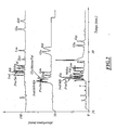
- the figure 2 refers to the example below.
- Two-dimensional separation in a single capillary purification and separation of a mixture of amino acid derivatives.
- the process of the invention was used to perform both (1) the purification of a complex mixture and (2) the analysis of the constituents of the mixture thus purified, using only a single capillary .
- the reaction-derived amino acid mixture initially contains 10 -3 mol / L of each amino acid (serine (Ser), proline (Pro), alpha-isobutyric acid (AIB), Valine (Val), isovaline ( IVal), alanine (Ala), glycine (Gly) leucine (Leu), isoleucine (Ileu), methyl-leucine (Meleu), glutamate (Glu), asparatate (Asp).
- the isocyanate functional compounds thus formed react with the amine function of the amino acids to give the amino acid derivative according to the following reaction:
- a virgin silica capillary with an internal diameter of 25 microns and a length equal to 30 cm was used.
- a detector was placed 20 cm from the capillary outlet (detection by UV absorbance at 214 nm). It was worked at a temperature of 25 ° C.
- the capillary was filled by a first separating medium which is a solution S1 consisting of a 200 mM sodium borate buffer, pH 9.2 in a water / isopropanol (85/15 by volume) mixture.
- This solution S1 was injected under pressure into the capillary.
- the capillary was purged for 5 minutes with the borate buffer.
- the mixture to be analyzed was then injected into the capillary at a pressure of 0.3 psi (2.07 Pa) for 3 seconds.
- the time T put by the impurities was measured to cover the first 10 cm of the capillary (from the inlet to the detector) and, from the moment these impurities were detected, they were allowed to migrate during the 2T time (necessary to cover the remaining 20 centimeters), plus a few tens of seconds to ensure that all the impurities were eliminated. .
- the direction of the polarity applied between the two ends of the capillary ie by applying a potential difference of -20 kV between the inlet and the outlet of the capillary
- the various compounds were remixed and thus obtained near the inlet of the capillary a fraction of the initial mixture, namely the compounds of interest of the mixture without the impurities initially present.
- the inlet of the capillary was immersed in a solution S2 comprising a 200 mM sodium borate buffer, pH 9.2 in a water / isopropanol mixture supplemented with 50 mM of SDS (surfactant: sodium dodecyl sulphate, forming micelles in the medium, to better separate the different amino acids derived according to their chemical nature).
- SDS surfactant: sodium dodecyl sulphate, forming micelles in the medium, to better separate the different amino acids derived according to their chemical nature).
- This new separating medium S2 was introduced under pressure into the capillary, so as to migrate the fraction separated in step (b) to the capillary outlet (without however taking it out) and to fill the capillary with the new separation medium.
- a potential difference of +20 kV was applied between the inlet of the dipped capillary in a container filled with solution S2, and the outlet also dipped into a container filled with solution S2.
- step (d) For comparative purposes, it is represented on the lower part of the figure 2 the electropherogram corresponding to an electrophoretic separation of the mixture under the conditions of step (d), using the SDS micelle solution S2 without the prior purification of step (a).
- This electropherogram shows numerous parasitic peaks (indexed by a star) which disappear under the conditions of the process of the invention.
- the separation as obtained can be further improved by replacing the solution S1 employed in steps (a) with a solution S1 of lower ionic strength than the solution S2. This point was checked by using a 50mM solution S1 'in borate buffer. Pre-concentration of the species was thus obtained with an increase in peak efficiencies. The improvement of the separation is visible on the electropherogram of the top of the figure 2 (25 micron diameter and 50mM solution S1 ').
Landscapes
- Health & Medical Sciences (AREA)
- Life Sciences & Earth Sciences (AREA)
- Molecular Biology (AREA)
- Chemical & Material Sciences (AREA)
- Chemical Kinetics & Catalysis (AREA)
- Electrochemistry (AREA)
- Physics & Mathematics (AREA)
- Analytical Chemistry (AREA)
- Biochemistry (AREA)
- General Health & Medical Sciences (AREA)
- General Physics & Mathematics (AREA)
- Immunology (AREA)
- Pathology (AREA)
- Other Investigation Or Analysis Of Materials By Electrical Means (AREA)
- Electrostatic Separation (AREA)
- Investigating Or Analysing Biological Materials (AREA)
- Saccharide Compounds (AREA)
- Peptides Or Proteins (AREA)
Claims (19)
- Verfahren zum Trennen der Bestandteile eines Gemischs M durch kappillare Elektrophorese im Innern einer einzigen Kapillare, wobei das genannte Verfahren die folgenden Schritte beeinhaltet:(A) Einführen und Migrierenlassen der Bestandteile des Gemischs M im Innern der Kapillare mit einer Kapillarelektrophoresetechnik unter der Wirkung einer zwischen den Eingang und den Ausgang der Kapillare angelegten Potentialdifferenz unter Verwendung eines ersten Trennmediums MS1 auf eine solche Weise, dass eine Trennung der Bestandteile des Gemischs M im Innern der Kapillare gemäß deren Migrationsgeschwindigkeit unter den Bedingungen von Schritt (A) erzielt wird;(B) Isolieren einer Fraktion F der in Schritt (A) getrennten Bestandteile in der Kapillare und Migrierenlassen der genannten isolierten Fraktion F in die Nähe eines der Enden der Kapillare, wobei diese Fraktion F durch Ausführen eines und/oder mehrerer der folgenden Schritte im Innern der Kapillare gehalten wird:(B.1) Evakuieren eines Teils der Bestandteile aus der Kapillare, die die höchsten Migrationsgeschwindigkeiten unter den Elektrophoresebedingungen von Schritt (A) haben, durch Migrierenlassen dieser Bestandteile zum Ausgang der Kapillare, eventuell unter Beibehaltung der Potentialdifferenz von Schritt (A) ; und/oder(B.2) Evakuieren eines Teils der Bestandteile aus der Kapillare, die die niedrigsten Migrationsgeschwindigkeiten unter den Elektrophoresebedingungen von Schritt (A) haben, durch Migrierenlassen diester Bestandteile zum Eingang der Kapillare, eventuell durch Aufbringen eines Überdrucks am Ausgang der Kapillare und/oder durch Anlegen einer Potentialpolaritätsdifferenz, die der von Schritt (A) entgegengesetzt ist, zwischen dem Eingang und dem Ausgang der Kapillare,
wobei im Sinne von Schritt (B) unter "Eingang" der Kapillare das Ende der Kapillare zu verstehen ist, an der die Injektion stattfindet, wobei der "Ausgang" das andere Ende ist;(C) Einleiten, durch Aufbringen einer Druckdifferenz zwischen die Enden der Kapillare, eines zweiten Trennmediums MS2, separat von dem in Schritt (A) verwendeten Trennmedium MS1, durch das Ende der Kapillare, in deren Nähe sich die Fraktion F befindet, wodurch die Fraktion F zum anderen Ende der Kapillare migriert wird und die Kapillare mit dem Trennmedium MS2 gefüllt wird; und(D) Bewirken einer Kapillarelektrophorese im Innern der so mit dem Trennmedium MS2 gefüllten Kapillare durch Migrierenlassen der Bestandteile der Fraktion F unter der Wirkung einer zwischen den Eingang und den Ausgang der Kapillare angelegten Potentialdiffferenz unter Verwendung des Mediums MS2 als Trennmedium. - Verfahren nach Anspruch 1, wobei Schritt (B) darin besteht, Schritt (B.2) auszuführen, ohne Schritt (B.1) auszuführen, wobei die im Innern der Kapillare isolierte Fraktion jetzt eine Kopftraktion ist.
- Verfahren nach Anspruch 2, wobei die Kopffraktion F durch die Bestandteile der Kopsspitze gebildet wird, die auf einem Elektrophorese-Elektropherogramm von Schritt (A) beobachtet werden kann.
- Verfahren nach Anspruch 1, wobei Schritt (B) darin besteht, Schritte (B.1) auszuführen, um eine Kopffraktion zu evakuieren, dann Schritt (B.2), um eine Schwanzfraktion zu evakuieren, wobei die im Innern der Kapillare isolierte Fraktion F eine Mittelfraktion ist.
- Verfahren nach Anspruch 4, wobei die Mittelfraktion F durch die Bestandteile einer der Kopfspitzen zwischen der Schwanzspitze and der Kopfspitze gebildet wird, die auf einem Elektrophorese-Elektropherogramm von Schritt (A) beobachtet werden können.
- Verfahren nach Anspruch 1, wobei Schritt (B) darin besteht, Schritt (B.1) auszuführen, ohne Schritt (B.2) auszuführen, wobei die im Innern der Kapillare isolierte Fraktion jetzt eine Schwanzfraktion ist.
- Verfahren nach Anspruch 6, wobei die Schwanzfraktion F durch die Bestandteile der Schwanzspitze gebildet wird, die auf einem Elektrophorese-Elektropherogramm von Schritt (A) beobachter werden kann.
- Verfahren nach einem der Ansprüche 1. bis 7, wobei das in Schritt (C) eingeleitete Trennmedium MS2 ein elektrisch stärker leitendes Medium ist als das in Schritt (A) verwendete Trennmedium MS1, z.B. ein Medium mit einer Ionenstärke, die höher ist als die des Trennmediums MS1.
- Verfahren nach einem der Ansprüche 1 bis 8, bei dem in Schritt (C) zunächst eine geringe Menge eines ersten Trennmediums ms2 , das sich von den Medien MS1 und MS2 unterscheidet, dann das Medium MS2, um dadurch eine Kapillare zu erhalten, das mit dem Trennmedium MS2 mit der Fraktion F gefüllt ist, die in der Nähe eines der Enden der Kapillare getrennt werden soll, und eine geringe Menge Medium ms2 zwischen der Fraktion F und dem Trennmedium MS2 eingeleitet wird, wobei diese geringe Menge Medium ms2 die Funktion einer Elektrolytübergangszone in Trennschritt (D) ausübt.
- Verfahren nach einem der Ansprüche 1 bis 9, bei dem in Schritt (A) nach der Injektion des Gemischs M und vor der Trennung eine geringe Menge eines Elektolyts eingeleitet wird, der vorteilhafterweise elektrisch weniger leitet als das Medium MS1, wobei der so injizierte Elektrolyt eine Elektrolytzone neben dem Gemisch M in der Kapillare bildet.
- Verfahren nach einem der Ansprüche 1 bis 10, bei dem das in Schritt (C) eingeleitete Trennmedium MS2 ein Medium ist, das Polymere in Lösung oder in Gelform umfasst.
- Verfahren nach einem der Ansprüche 1 bis 10, bei dem das in Schritt (C) eingeleitete Trerinmedium MS2 ein micellares Medium ist.
- Verfahren nach einem der Ansprüche 1 bis 12, bei dem sich das in Schritt (C) eingeleitete Trennmedium MS2 durch seinen pH-Wert von dem Medium MS1 unterscheidet.
- Verfahren nach einem der Ansprüche 1 bis 13, das eine drei- oder multidimensionale Trennung ermöglicht die nach den Schritten (A) bis (D) ein oder mehrere zusätzliche Trenn/Elektrophoreseanalyse-Zyklen beinhaltet, die jeweils die folgenden Schritte (B-bis) bis (D-bis) beinhalten:(B-bis) Isolieren, in der in den Schritten (A) bis (D) verwendeten Kapillare, einer Fraktion (f) von Bestandteilen, die in dem Schritt von Schritt (B-bis) getrennt wurden, und Migrierenlassen der genannten isolierten Fraktion (f) in der Nähe eines der Enden der Kapillare, wobei diese Fraktion (f) im Innern der Kapillare gehalten wird,(C-bis) Einleiten, durch Aufbringen eines Druckdifferentials zwischen die Enden der Kapillare, eines Trennmediums MS2 bis in die Kapillare, verschieden von dem in den vorherigen Trennschritten verwendeten Trennmedium, wobei dieses Einleiten des neuen Trennmediums durch das Ende der Kapillare erfolgt, in dessen Nähe sich die Fraktion (f) aus Schritt (B-bis) befindet; und(D-bis) Bewirken einer Kapillarelektrophorese im Innern der so mit dem Trennmedium MS2 bis gefüllten Kapillare durch Migrierenlassen der Bestandteile der Fraktion (f) unter der Wirkung einer zwischen den Eingang und den Ausgang der Kapillare angelegten Potentialdifferenz unter Verwendung des Mediums MS2 bis als Trennmedium.
- Verfahren nach Anspruch 14, das Folgendes beinhaltet:einen Schritt (A) zum Reinigen des zu analysierenden Mediums M;- einen Schritt (D) zum Trennen der gelösten Stoffe gemäß einem ersten Molekülkriterium, vorzugsweise mit einer höheren Ionenstärke als in Schritt (A);- einen Schritt (D-bis) zum Trennen der gelösten Stoffe gemäß einem zweiten Molekülkriterium, vorteilhafterweise mit einer höheren Ionenstärke als in Schritt (D).
- Verfahren nach einem der Ansprüche 1 bis 15, wobei die verwendete Kapillare einen Innendurchmesser zwischen 5 und 100 Mikron hat.
- Verfahren nach einem der Ansprüche 1 bis 16, wobei die verwendete Kapillare eine Länge von weniger als 1 m hat.
- Verfahren nach einem der Ansprüche 1 bis 17, bei dem die Mischung M eine Urinprobe, eine Blutprobe oder ein Proteingemisch ist.
- Verfahren nach einem der Anspruche 1 bis 18, bei dem das Gemisch M Proteine, Peptide, Nukleinsäuren, Polysaccharide, Huminsäüren, Fluvinsäuren, Latexe, Kolloide, Nanopartikeln und/oder synthetische Polymere umfasst.
Applications Claiming Priority (2)
| Application Number | Priority Date | Filing Date | Title |
|---|---|---|---|
| FR0609052A FR2907028B1 (fr) | 2006-10-16 | 2006-10-16 | Electrophorese capillaire bi-ou multidimensionnelle au sein d'un unique capillaire. |
| PCT/FR2007/001683 WO2008046995A1 (fr) | 2006-10-16 | 2007-10-15 | Électrophorèse capillaire bi - ou multidimensionnelle au sein d'un unique capillaire |
Publications (2)
| Publication Number | Publication Date |
|---|---|
| EP2080020A1 EP2080020A1 (de) | 2009-07-22 |
| EP2080020B1 true EP2080020B1 (de) | 2012-03-28 |
Family
ID=38262160
Family Applications (1)
| Application Number | Title | Priority Date | Filing Date |
|---|---|---|---|
| EP07858445A Not-in-force EP2080020B1 (de) | 2006-10-16 | 2007-10-15 | Zwei- oder mehrdimensionale kapillare elektrophorese in einem einzelkapillar |
Country Status (5)
| Country | Link |
|---|---|
| US (1) | US20100300880A1 (de) |
| EP (1) | EP2080020B1 (de) |
| AT (1) | ATE551602T1 (de) |
| FR (1) | FR2907028B1 (de) |
| WO (1) | WO2008046995A1 (de) |
Families Citing this family (3)
| Publication number | Priority date | Publication date | Assignee | Title |
|---|---|---|---|---|
| CN101852764A (zh) * | 2010-05-23 | 2010-10-06 | 青岛科技大学 | 一种中心切割二维毛细管电泳在柱电化学装置及其应用 |
| CN109444246B (zh) * | 2018-11-01 | 2023-11-21 | 宁波大学 | 一种基于电压极性转换的瞬态毛细管等速电泳装置及方法 |
| CN109444247B (zh) * | 2018-11-01 | 2024-01-09 | 宁波大学 | 一种瞬态毛细管等速电泳-电喷雾-质谱联用装置及方法 |
Family Cites Families (5)
| Publication number | Priority date | Publication date | Assignee | Title |
|---|---|---|---|---|
| JPS5821553A (ja) * | 1981-07-31 | 1983-02-08 | Shimadzu Corp | 電気泳動分析方法および装置 |
| WO1995008529A1 (en) * | 1993-09-20 | 1995-03-30 | Waters Corporation | Chiral surfactants and methods for their use in chiral separations |
| US6537432B1 (en) * | 1998-02-24 | 2003-03-25 | Target Discovery, Inc. | Protein separation via multidimensional electrophoresis |
| WO2000057170A1 (en) * | 1999-03-19 | 2000-09-28 | The Governors Of The University Of Alberta | Automated 2-dimensional analysis of biological and other samples |
| FR2859113B1 (fr) * | 2003-08-29 | 2006-02-17 | Centre Nat Rech Scient | Procede de separation bidimensionnelle par electrophorese capillaire realise dans un seul capillaire |
-
2006
- 2006-10-16 FR FR0609052A patent/FR2907028B1/fr not_active Expired - Fee Related
-
2007
- 2007-10-15 AT AT07858445T patent/ATE551602T1/de active
- 2007-10-15 EP EP07858445A patent/EP2080020B1/de not_active Not-in-force
- 2007-10-15 WO PCT/FR2007/001683 patent/WO2008046995A1/fr not_active Ceased
- 2007-10-15 US US12/445,660 patent/US20100300880A1/en not_active Abandoned
Also Published As
| Publication number | Publication date |
|---|---|
| WO2008046995A1 (fr) | 2008-04-24 |
| ATE551602T1 (de) | 2012-04-15 |
| US20100300880A1 (en) | 2010-12-02 |
| FR2907028A1 (fr) | 2008-04-18 |
| FR2907028B1 (fr) | 2009-01-30 |
| EP2080020A1 (de) | 2009-07-22 |
Similar Documents
| Publication | Publication Date | Title |
|---|---|---|
| EP2880434B1 (de) | Verfahren zur abtrennung von biologischen molekülen und zellen in lösung | |
| CA1276589C (fr) | Procedes et appareils d'electrophorese preparative | |
| FR2668473A1 (fr) | Procede pour revetir une surface solide, portant des groupes silanols exposes, pour diminuer la presence de leurs charges electro-statiques, et application a la separation de proteines. | |
| CA2527351C (fr) | Procede d`analyse de l`hemoglobine par electrophorese capillaire, trousse pour electrophorese capillaire et utilisation de ralentisseur de flux dans un tel procede | |
| Macià et al. | Application of capillary electrophoresis with different sample stacking strategies for the determination of a group of nonsteroidal anti‐inflammatory drugs in the low μg∵ L− 1 concentration range | |
| FR2819888A1 (fr) | Procede de separation de proteines par electrophorese capillaire et compositions de tampon pour electrophorese capillaire | |
| EP0181266B1 (de) | Verfahren zur Herstellung einer stationären Phase für chromatographische Säule, die so erhaltene chromatographische Säule und ihre Verwendung | |
| EP2080020A1 (de) | Zwei- oder mehrdimensionale kapillare elektrophorese in einem einzelkapillar | |
| EP1660882B1 (de) | Zweidimensionale trennung mittels in einer einzelnen kapillare durchgeführter kapillarelektrophorese | |
| FR3024544B1 (fr) | Procede et dispositif de concentration de molecules ou objets dissous en solution. | |
| EP3320321B1 (de) | System zur konzentration und vorkonzentration durch probenstapelung und/oder -aufreinigung zur analyse | |
| Macià et al. | Analysis of nonsteroidal anti-inflammatory drugs in water samples using microemulsion electrokinetic capillary chromatography under pH-suppressed electroosmotic flow with an on-column preconcentration technique | |
| FR2810905A1 (fr) | Additif pour minimiser les phenomenes d'adsorption et/ou d'electroosmose | |
| EP2067017B1 (de) | Bestimmung der hydrodynamischen radien der komponenten einer mischung durch analyse einer durch eine kapillarelektrophorese-trennung hervorgerufenen taylor-dispersion | |
| FR2819889A1 (fr) | Procede d'electrophorese capillaire en solution libre a ph alcalin | |
| Awadallah et al. | Quantitation of talinolol and other β‐blockers by capillary electrophoresis for in vitro drug absorption studies | |
| BE1020346A5 (fr) | Procede et trousse de detection et/ou d'analyse par electrophorese ca pillaire. | |
| Cheng et al. | Chiral separation of sertraline with microemulsion electrokinetic chromatography on a polymer/β-cyclodextrin assembling molecular film modified capillary | |
| Ahmed et al. | pH-assisted in-line pseudophase microextraction and separation with tridodecylmethylammonium chloride admicelles in open-tubular capillary-based separations | |
| EP3538882B1 (de) | Vorrichtung, system und verfahren im zusammenhang mit der vorkonzentrierung von analyten | |
| WO2001062369A2 (fr) | Compositions utilisables pour l'hydratation d'un support d'electrophorese, pour l'electrophorese de zone | |
| WO2006037930A1 (fr) | Procede d'obtention d'un support pour electrophoserese incluant des cyclodextrat ines | |
| EP1828226A2 (de) | Verfahren zur extraktion von protein zu dessen auftrennung |
Legal Events
| Date | Code | Title | Description |
|---|---|---|---|
| PUAI | Public reference made under article 153(3) epc to a published international application that has entered the european phase |
Free format text: ORIGINAL CODE: 0009012 |
|
| 17P | Request for examination filed |
Effective date: 20090415 |
|
| AK | Designated contracting states |
Kind code of ref document: A1 Designated state(s): AT BE BG CH CY CZ DE DK EE ES FI FR GB GR HU IE IS IT LI LT LU LV MC MT NL PL PT RO SE SI SK TR |
|
| 17Q | First examination report despatched |
Effective date: 20110621 |
|
| GRAP | Despatch of communication of intention to grant a patent |
Free format text: ORIGINAL CODE: EPIDOSNIGR1 |
|
| DAX | Request for extension of the european patent (deleted) | ||
| GRAS | Grant fee paid |
Free format text: ORIGINAL CODE: EPIDOSNIGR3 |
|
| GRAA | (expected) grant |
Free format text: ORIGINAL CODE: 0009210 |
|
| AK | Designated contracting states |
Kind code of ref document: B1 Designated state(s): AT BE BG CH CY CZ DE DK EE ES FI FR GB GR HU IE IS IT LI LT LU LV MC MT NL PL PT RO SE SI SK TR |
|
| REG | Reference to a national code |
Ref country code: GB Ref legal event code: FG4D Free format text: NOT ENGLISH |
|
| REG | Reference to a national code |
Ref country code: CH Ref legal event code: EP |
|
| REG | Reference to a national code |
Ref country code: AT Ref legal event code: REF Ref document number: 551602 Country of ref document: AT Kind code of ref document: T Effective date: 20120415 |
|
| REG | Reference to a national code |
Ref country code: IE Ref legal event code: FG4D Free format text: LANGUAGE OF EP DOCUMENT: FRENCH |
|
| REG | Reference to a national code |
Ref country code: DE Ref legal event code: R096 Ref document number: 602007021692 Country of ref document: DE Effective date: 20120524 |
|
| REG | Reference to a national code |
Ref country code: NL Ref legal event code: VDEP Effective date: 20120328 |
|
| PG25 | Lapsed in a contracting state [announced via postgrant information from national office to epo] |
Ref country code: LT Free format text: LAPSE BECAUSE OF FAILURE TO SUBMIT A TRANSLATION OF THE DESCRIPTION OR TO PAY THE FEE WITHIN THE PRESCRIBED TIME-LIMIT Effective date: 20120328 |
|
| LTIE | Lt: invalidation of european patent or patent extension |
Effective date: 20120328 |
|
| PG25 | Lapsed in a contracting state [announced via postgrant information from national office to epo] |
Ref country code: FI Free format text: LAPSE BECAUSE OF FAILURE TO SUBMIT A TRANSLATION OF THE DESCRIPTION OR TO PAY THE FEE WITHIN THE PRESCRIBED TIME-LIMIT Effective date: 20120328 Ref country code: LV Free format text: LAPSE BECAUSE OF FAILURE TO SUBMIT A TRANSLATION OF THE DESCRIPTION OR TO PAY THE FEE WITHIN THE PRESCRIBED TIME-LIMIT Effective date: 20120328 Ref country code: GR Free format text: LAPSE BECAUSE OF FAILURE TO SUBMIT A TRANSLATION OF THE DESCRIPTION OR TO PAY THE FEE WITHIN THE PRESCRIBED TIME-LIMIT Effective date: 20120629 |
|
| REG | Reference to a national code |
Ref country code: AT Ref legal event code: MK05 Ref document number: 551602 Country of ref document: AT Kind code of ref document: T Effective date: 20120328 |
|
| PG25 | Lapsed in a contracting state [announced via postgrant information from national office to epo] |
Ref country code: CY Free format text: LAPSE BECAUSE OF FAILURE TO SUBMIT A TRANSLATION OF THE DESCRIPTION OR TO PAY THE FEE WITHIN THE PRESCRIBED TIME-LIMIT Effective date: 20120328 |
|
| PG25 | Lapsed in a contracting state [announced via postgrant information from national office to epo] |
Ref country code: RO Free format text: LAPSE BECAUSE OF FAILURE TO SUBMIT A TRANSLATION OF THE DESCRIPTION OR TO PAY THE FEE WITHIN THE PRESCRIBED TIME-LIMIT Effective date: 20120328 Ref country code: IS Free format text: LAPSE BECAUSE OF FAILURE TO SUBMIT A TRANSLATION OF THE DESCRIPTION OR TO PAY THE FEE WITHIN THE PRESCRIBED TIME-LIMIT Effective date: 20120728 Ref country code: SI Free format text: LAPSE BECAUSE OF FAILURE TO SUBMIT A TRANSLATION OF THE DESCRIPTION OR TO PAY THE FEE WITHIN THE PRESCRIBED TIME-LIMIT Effective date: 20120328 Ref country code: PL Free format text: LAPSE BECAUSE OF FAILURE TO SUBMIT A TRANSLATION OF THE DESCRIPTION OR TO PAY THE FEE WITHIN THE PRESCRIBED TIME-LIMIT Effective date: 20120328 Ref country code: SE Free format text: LAPSE BECAUSE OF FAILURE TO SUBMIT A TRANSLATION OF THE DESCRIPTION OR TO PAY THE FEE WITHIN THE PRESCRIBED TIME-LIMIT Effective date: 20120328 Ref country code: CZ Free format text: LAPSE BECAUSE OF FAILURE TO SUBMIT A TRANSLATION OF THE DESCRIPTION OR TO PAY THE FEE WITHIN THE PRESCRIBED TIME-LIMIT Effective date: 20120328 Ref country code: EE Free format text: LAPSE BECAUSE OF FAILURE TO SUBMIT A TRANSLATION OF THE DESCRIPTION OR TO PAY THE FEE WITHIN THE PRESCRIBED TIME-LIMIT Effective date: 20120328 |
|
| PG25 | Lapsed in a contracting state [announced via postgrant information from national office to epo] |
Ref country code: SK Free format text: LAPSE BECAUSE OF FAILURE TO SUBMIT A TRANSLATION OF THE DESCRIPTION OR TO PAY THE FEE WITHIN THE PRESCRIBED TIME-LIMIT Effective date: 20120328 Ref country code: PT Free format text: LAPSE BECAUSE OF FAILURE TO SUBMIT A TRANSLATION OF THE DESCRIPTION OR TO PAY THE FEE WITHIN THE PRESCRIBED TIME-LIMIT Effective date: 20120730 |
|
| PG25 | Lapsed in a contracting state [announced via postgrant information from national office to epo] |
Ref country code: NL Free format text: LAPSE BECAUSE OF FAILURE TO SUBMIT A TRANSLATION OF THE DESCRIPTION OR TO PAY THE FEE WITHIN THE PRESCRIBED TIME-LIMIT Effective date: 20120328 Ref country code: DK Free format text: LAPSE BECAUSE OF FAILURE TO SUBMIT A TRANSLATION OF THE DESCRIPTION OR TO PAY THE FEE WITHIN THE PRESCRIBED TIME-LIMIT Effective date: 20120328 Ref country code: AT Free format text: LAPSE BECAUSE OF FAILURE TO SUBMIT A TRANSLATION OF THE DESCRIPTION OR TO PAY THE FEE WITHIN THE PRESCRIBED TIME-LIMIT Effective date: 20120328 |
|
| PLBE | No opposition filed within time limit |
Free format text: ORIGINAL CODE: 0009261 |
|
| STAA | Information on the status of an ep patent application or granted ep patent |
Free format text: STATUS: NO OPPOSITION FILED WITHIN TIME LIMIT |
|
| PG25 | Lapsed in a contracting state [announced via postgrant information from national office to epo] |
Ref country code: IT Free format text: LAPSE BECAUSE OF FAILURE TO SUBMIT A TRANSLATION OF THE DESCRIPTION OR TO PAY THE FEE WITHIN THE PRESCRIBED TIME-LIMIT Effective date: 20120328 |
|
| 26N | No opposition filed |
Effective date: 20130103 |
|
| REG | Reference to a national code |
Ref country code: DE Ref legal event code: R097 Ref document number: 602007021692 Country of ref document: DE Effective date: 20130103 |
|
| BERE | Be: lapsed |
Owner name: CENTRE NATIONAL DE LA RECHERCHE SCIENTIFIQUE - CN Effective date: 20121031 |
|
| PG25 | Lapsed in a contracting state [announced via postgrant information from national office to epo] |
Ref country code: ES Free format text: LAPSE BECAUSE OF FAILURE TO SUBMIT A TRANSLATION OF THE DESCRIPTION OR TO PAY THE FEE WITHIN THE PRESCRIBED TIME-LIMIT Effective date: 20120709 |
|
| PG25 | Lapsed in a contracting state [announced via postgrant information from national office to epo] |
Ref country code: MC Free format text: LAPSE BECAUSE OF NON-PAYMENT OF DUE FEES Effective date: 20121031 |
|
| REG | Reference to a national code |
Ref country code: CH Ref legal event code: PL |
|
| GBPC | Gb: european patent ceased through non-payment of renewal fee |
Effective date: 20121015 |
|
| REG | Reference to a national code |
Ref country code: IE Ref legal event code: MM4A |
|
| REG | Reference to a national code |
Ref country code: FR Ref legal event code: ST Effective date: 20130628 |
|
| PG25 | Lapsed in a contracting state [announced via postgrant information from national office to epo] |
Ref country code: DE Free format text: LAPSE BECAUSE OF NON-PAYMENT OF DUE FEES Effective date: 20130501 Ref country code: BE Free format text: LAPSE BECAUSE OF NON-PAYMENT OF DUE FEES Effective date: 20121031 Ref country code: GB Free format text: LAPSE BECAUSE OF NON-PAYMENT OF DUE FEES Effective date: 20121015 Ref country code: IE Free format text: LAPSE BECAUSE OF NON-PAYMENT OF DUE FEES Effective date: 20121015 Ref country code: CH Free format text: LAPSE BECAUSE OF NON-PAYMENT OF DUE FEES Effective date: 20121031 Ref country code: BG Free format text: LAPSE BECAUSE OF FAILURE TO SUBMIT A TRANSLATION OF THE DESCRIPTION OR TO PAY THE FEE WITHIN THE PRESCRIBED TIME-LIMIT Effective date: 20120628 Ref country code: LI Free format text: LAPSE BECAUSE OF NON-PAYMENT OF DUE FEES Effective date: 20121031 |
|
| REG | Reference to a national code |
Ref country code: DE Ref legal event code: R119 Ref document number: 602007021692 Country of ref document: DE Effective date: 20130501 |
|
| PG25 | Lapsed in a contracting state [announced via postgrant information from national office to epo] |
Ref country code: FR Free format text: LAPSE BECAUSE OF NON-PAYMENT OF DUE FEES Effective date: 20121031 |
|
| PG25 | Lapsed in a contracting state [announced via postgrant information from national office to epo] |
Ref country code: MT Free format text: LAPSE BECAUSE OF FAILURE TO SUBMIT A TRANSLATION OF THE DESCRIPTION OR TO PAY THE FEE WITHIN THE PRESCRIBED TIME-LIMIT Effective date: 20120328 |
|
| PG25 | Lapsed in a contracting state [announced via postgrant information from national office to epo] |
Ref country code: TR Free format text: LAPSE BECAUSE OF FAILURE TO SUBMIT A TRANSLATION OF THE DESCRIPTION OR TO PAY THE FEE WITHIN THE PRESCRIBED TIME-LIMIT Effective date: 20120328 |
|
| PG25 | Lapsed in a contracting state [announced via postgrant information from national office to epo] |
Ref country code: LU Free format text: LAPSE BECAUSE OF NON-PAYMENT OF DUE FEES Effective date: 20121015 |
|
| PG25 | Lapsed in a contracting state [announced via postgrant information from national office to epo] |
Ref country code: HU Free format text: LAPSE BECAUSE OF FAILURE TO SUBMIT A TRANSLATION OF THE DESCRIPTION OR TO PAY THE FEE WITHIN THE PRESCRIBED TIME-LIMIT Effective date: 20071015 |