EP2080061B1 - Dispositif d'inspection de capteur d'images - Google Patents
Dispositif d'inspection de capteur d'images Download PDFInfo
- Publication number
- EP2080061B1 EP2080061B1 EP07838245.4A EP07838245A EP2080061B1 EP 2080061 B1 EP2080061 B1 EP 2080061B1 EP 07838245 A EP07838245 A EP 07838245A EP 2080061 B1 EP2080061 B1 EP 2080061B1
- Authority
- EP
- European Patent Office
- Prior art keywords
- inspection device
- camera
- lens
- tubular body
- mating portion
- Prior art date
- Legal status (The legal status is an assumption and is not a legal conclusion. Google has not performed a legal analysis and makes no representation as to the accuracy of the status listed.)
- Active
Links
Images

Classifications
-
- G—PHYSICS
- G03—PHOTOGRAPHY; CINEMATOGRAPHY; ANALOGOUS TECHNIQUES USING WAVES OTHER THAN OPTICAL WAVES; ELECTROGRAPHY; HOLOGRAPHY
- G03B—APPARATUS OR ARRANGEMENTS FOR TAKING PHOTOGRAPHS OR FOR PROJECTING OR VIEWING THEM; APPARATUS OR ARRANGEMENTS EMPLOYING ANALOGOUS TECHNIQUES USING WAVES OTHER THAN OPTICAL WAVES; ACCESSORIES THEREFOR
- G03B19/00—Cameras
-
- G—PHYSICS
- G03—PHOTOGRAPHY; CINEMATOGRAPHY; ANALOGOUS TECHNIQUES USING WAVES OTHER THAN OPTICAL WAVES; ELECTROGRAPHY; HOLOGRAPHY
- G03B—APPARATUS OR ARRANGEMENTS FOR TAKING PHOTOGRAPHS OR FOR PROJECTING OR VIEWING THEM; APPARATUS OR ARRANGEMENTS EMPLOYING ANALOGOUS TECHNIQUES USING WAVES OTHER THAN OPTICAL WAVES; ACCESSORIES THEREFOR
- G03B17/00—Details of cameras or camera bodies; Accessories therefor
-
- H—ELECTRICITY
- H04—ELECTRIC COMMUNICATION TECHNIQUE
- H04N—PICTORIAL COMMUNICATION, e.g. TELEVISION
- H04N17/00—Diagnosis, testing or measuring for television systems or their details
- H04N17/002—Diagnosis, testing or measuring for television systems or their details for television cameras
-
- H—ELECTRICITY
- H04—ELECTRIC COMMUNICATION TECHNIQUE
- H04N—PICTORIAL COMMUNICATION, e.g. TELEVISION
- H04N23/00—Cameras or camera modules comprising electronic image sensors; Control thereof
- H04N23/50—Constructional details
- H04N23/55—Optical parts specially adapted for electronic image sensors; Mounting thereof
Definitions
- the present invention is generally directed to inspection devices for digital image recorders. More specifically, the present invention relates to a device that is used to inspect the image sensor of a digital image recorder, such as a digital camera.
- Digital cameras have become pervasive in photography since their commercial introduction in the 1990s. In fact, many camera manufacturers have ceased production and/or development of conventional film cameras and focused entirely on digital models. Digital cameras provide various conveniences over film cameras that have increased their popularity. For example, digital cameras provide images that are readily downloadable and printable without requiring a photo lab. In addition, digital cameras generally include a liquid crystal display that provides instant feedback as to the image quality. Furthermore, digital cameras allow a user to experiment and view the outcome without the expense of exhausting film supply. If a digital image is found undesirable it may be deleted and a new image may be recorded in its place. Digital cameras also allow the user to change film speed without being required to change the recording media. In a film camera, the film speed may only be changed by replacing the film with film having the desired film speed.
- An image sensor is used in digital cameras in place of film to record an image that is projected into the camera.
- the image sensor is generally a charge-coupled device (CCD) or a complimentary metal-oxide semiconductor (CMOS) sensor that is built into the camera body during manufacture.
- CCD charge-coupled device
- CMOS complimentary metal-oxide semiconductor
- DSLR digital single-lens reflex camera
- dust particles incident on the sensor reduces image quality.
- Image sensors are not designed to be replaced so the exposure of the sensor to dust requires sensor cleaning. Cleaning the image sensor exposes the sensor to the risk of damage so manual sensor cleaning is preferably undertaken only when sensor contamination has reached significant levels. Because of the size of dust particles and accessibility to the sensor, inspection of the sensor to determine the level of contamination is not a trivial task.
- a common method of inspecting a digital camera sensor to determine the level of contamination is to take a picture of a uniformly illuminated surface.
- the image is taken with a small aperture setting, e.g., f/22-f/45 and with the lens focused on the closest focus setting.
- the image is then reviewed on a computer monitor to determine the level of contamination.
- dust particles on the sensor produce visible spots on the image.
- the image provides a map of the dust particles that is flipped 180 degrees from top to bottom. Based on that image a user may determine whether the contamination is substantial enough to require cleaning. It has also been suggested to utilize the same technique, but to manipulate the image with image editing software to improve the dust particle mapping.
- Such methods present various disadvantages.
- One disadvantage of the method is that it requires access to a monitor to adequately view the image of the dust particles, but in many situations, such as when traveling, a monitor may not be available.
- the user desires to target the dirtiest portions of the sensor, it requires the user to correlate the locations presented in the flipped image with the actual particle locations on the sensor.
- such a method does not clearly indicate whether the contaminants are on the sensor, a lens or a filter surface.
- a still further disadvantage is that if image processing is utilized, such software may not be available or requires special knowledge to adequately perform the processing steps.
- Patent Application JP2005295152 describes an accessory for judging presence of foreign material on the imaging surface of a camera comprising a light source whose light is directed radially inward.
- the present invention provides an image sensor inspection device that does not require a monitor or image processing to determine the cleanliness of the image sensor.
- the inspection device allows a user to visually inspect the image sensor directly to determine if cleaning the sensor is required.
- an image sensor inspection device in accordance with appended claim 1.
- the inspection device may be coupled with a camera body and allows the user to visually inspect the camera's image sensor.
- the inspection device includes a housing and a fixed power lens suspended therein.
- the housing is configured to engage a lens interface of the camera body.
- the inspection device also includes a lighting assembly configured to illuminate the sensor so that debris present on the sensor may be easily viewed.
- the inspection device may include a second lens, i.e., a protective lens.
- the second lens is suspended in the housing and encloses a chamber between the lenses.
- the inspection device includes a mounting portion that is configured so that the inspection device may be mounted to camera bodies having differently configured lens interfaces, such as those offered by different camera manufacturers.
- Inspection device 10 is configured to be coupled to a camera body 2 at a lens interface 4 so that an image sensor 6 housed within body 2 may be visually inspected.
- Lens interface 4 is a portion of body 2 that in normal photographic use allows interchangeable lenses to be removably coupled to body 2.
- Inspection device 10 is coupled to camera body 2 at lens interface 4 so that the longitudinal axis of inspection device 10 is aligned with an optical axis of camera body 2. It should be appreciated that camera manufacturers generally have adopted specific configurations that allow a complimentary flanged mating portion of an interchangeable lens to be locked in place on camera body 2.
- Inspection device 10 includes a housing 12, a mating portion 14 and a lighting control 16. As shown, inspection device may also include a protective lens 18 mounted to an end of housing 12 opposite mating portion 14. Housing 12 holds and protects the various components of inspection device 10 during use and storage. Housing 12 is generally an elongate body that includes a central lumen that is sized to receive optical components that will be described in greater detail below.
- Housing 12 may have any length desired that is sufficient to house the optical components of inspection device 10.
- the length of housing 12, as shown, is approximately the length of a lens having a small focal length such as a wide angle lens so that a user is able to conveniently store inspection device 10 as they would any short lens.
- housing 12 may have a length in the range of 1 - 8 inches.
- Housing 12 may be made of any desired material such as brass, aluminum, steel or plastic. It should be appreciated that although housing 12 is monolithic in the embodiment shown, housing 12 may be assembled from multiple components, constructed from the same or different materials, that may be threaded, welded or otherwise adhered together. In addition, it should be appreciated that housing 12 may be adjustable so that the distance between the optical components (e.g., a primary lens 20) and mating portion 14 may be changed by the user. One or more coatings may be applied to the interior surface of housing 12 for protection and to reduce reflection and flare.
- a primary lens 20 e.g., a primary lens 20
- mating portion 14 may be changed by the user.
- One or more coatings may be applied to the interior surface of housing 12 for protection and to reduce reflection and flare.
- Mating portion 14 is included on inspection device 10 and is configured so that inspection device 10 may be temporarily coupled to lens interface 4 of camera body 2.
- Mating portion 14 may be configured to engage and lock onto camera body 2 as would a conventional interchangeable lens, or mating portion may be configured to engage lens interface 4 without locking onto camera body 2.
- mating portion 14 may be configured so that it includes portions that can engage camera bodies 2 that are produced by different manufacturers.
- mating portion 14 may include portions having different diameters so that a single inspection device 10 may be mounted to camera bodies produced by either Canon or Nikon, which have traditionally had differently configured lens interfaces.
- Lighting control 16 is coupled to and may extend through a side wall of housing 12 so that a user may trigger an internal lighting assembly when inspection device 10 is coupled to body 2.
- lighting control 16 is a push button that may be easily depressed by a user so that image sensor 6 may be illuminated for easy inspection. It should be appreciated that lighting control 16 may be any type of switch or sensor that allows a user to selectively turn a lighting assembly off and on.
- a cover included in lighting control 16 may be ultrasonically welded to housing 12.
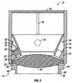
- inspection device 10 generally includes housing 12 that holds and protects the optical elements of inspection device 10.
- Primary lens 20 is held within housing 12 and provides magnification for visually inspecting image sensor 6.
- Primary lens 20 is preferably a fixed power lens that is aspherical.
- Lens 20 includes a circumferential flange 22 that allows lens 20 to be held in place by a retaining ring 24.
- lens 20 may be inserted into housing 12 so that lens flange 22 abuts a shoulder 26 of housing 12.
- retaining ring 24 is inserted into housing and a lens retaining flange 28 of retaining ring abuts lens flange 22 so that lens flange 22 is sandwiched between shoulder 26 and retaining flange 28.
- Retaining ring 24 is then coupled to housing 12, such as by an adhesive.
- lens 20 may be attached in a manner that allows movement of the lens with respect to housing 12 to make focal point adjustments.
- Retaining ring 24 is configured to house a lighting assembly that may be controlled by a user.
- retaining ring 24 includes a plurality of angled lighting bores 30 that are configured to receive a plurality of light sources, such as lightemitting diodes (LED) 32.
- LED lightemitting diodes
- the orientation of lighting bores 30 assures that LEDs 32 are pointed as desired radially inward and toward image sensor 6 when inspection device is coupled to camera body 2.
- lighting bores 30 may include shoulders 34 that engage a flange 36 included on LEDs 32 so that the position of of LEDs 32 within bores 30 is controlled.
- LEDs 32 are positioned proximal to the surface of primary lens 20 to provide a greater angle of illumination that is cast upon the surface of image sensor 6. It will be appreciated that any number of LEDs 32 may be included and they may be mounted with different angles of line of sight to support different lens focal points.
- a circumferential channel 38 is also included on retaining ring 24 that defines a conduit between retaining ring 24 and housing 12.
- Channel 38 is configured so that it intersects and is opened within lighting bores 30.
- Wires 40 are routed from LEDs 32 to lighting control 16 and a power source (not shown) through channel 38 so that wires 40 do not interfere with the fit of retaining ring 24 in housing 12.
- the power source may be any known power source, such as one or more batteries, and it may be mounted anywhere on or in inspection device 10, such as external of housing 12 or within retaining ring 24.
- wires 40 are included in a flex-circuit that is extended through channel 38 to a switch and coin cell battery located in lighting control 16 that is mounted on the outside of housing 12.
- any light source may be included in inspection device 10.
- any number of light sources may be included and if a plurality of light sources are included they may be distributed through inspection device 10 in any way.
- a pair of LEDs are included and spaced 180 degrees apart from one another as shown.
- the light sources may provide any color or wavelength of light desired.
- each light source may be adjustable for intensity and/or color.
- An alignment feature may also be included on the outer surface of retaining ring 24.
- the alignment feature may be provided so that retaining ring 24 can be easily aligned within housing 12.
- the alignment feature is a tab (not shown) that is received within an alignment channel 42 included in the interior of housing 12. The alignment features are used to properly align retaining ring 24 within housing 12 so that lighting control 16 is positioned properly with respect to the portion of the lighting assembly housed by retaining ring.
- mating portion 14 is included on housing 12 and is configured so that inspection device 10 may be temporarily coupled to lens interface 4 of body 2.
- mating portion 14 includes dual concentric flanges so that inspection device 10 may be coupled to camera bodies having different lens interface configurations.
- a first flange 44 extends from housing 12 and includes a plurality of tabs 46 that extend radially outward from flange 44. The outer diameter of flange 44 and the size of tabs 46 are selected to mate with a first camera body lens interface design.
- a second flange 48 extends from first flange 44 and includes a plurality of tabs 50 that extend radially outward from flange 48.
- Tabs 50 have an outer diameter that is preferably smaller than the outer diameter of first flange 44 so that tabs 50 will not hinder coupling a camera body with first flange 44.
- the outer diameter of second flange 48 and the size of tabs 50 are selected to mate with a second camera body lens interface design.
- tabs 46, 50 may be tapered so that rotation of inspection device 10 relative to camera body 2 about the longitudinal axis of inspection device 10 causes inspection device 10 and camera body 2 to be drawn together and locked together.
- tabs 46, 50 may be tapered in different directions so that rotation of inspection device 10 may lock into different camera bodies lens interface designs by relative rotation of inspection device 10 and camera body 2 in different directions.
- tabs 46, 50 may be configured so that inspection device 10 locks in Nikon camera bodies by counterclockwise rotation and in Canon camera bodies by clockwise rotation.
- any releasable locking mechanism may be included in addition to, or in lieu of, tabs 46, 50.
- a retractable body may be included on either the camera body or inspection device that selectively extends into a dimple or cavity of the other.
- mating portion 14 may be configured to engage any lens interface design desired.
- tabs 46, 50 may be omitted so that inspection device 10 is simply held against lens interface 4 of camera body 2.
- inspection device 10 is not locked with camera body, but is held by the user against lens interface 4 during inspection.
- Such a configuration may be especially desirable for quality control inspectors at camera manufacturers so that there is less potential for wear on lens interface 4.
- Inspection device 10 also preferably includes protective lens 18 coupled to housing 12 at an end of housing 12 that is opposite mating portion 14.
- Protective lens 18 is sealed with housing to prevent contaminants from entering the interior of inspection device 10.
- Protective lens 18 may be a clear lens, a polarizer filter or any other filter that permits the user to view image sensor 6. It should be appreciated that any type of filter may be used. It should be appreciated that a filter mount may be included on housing so that a removable filtermay be used in conjunction with protective lens 18.
- Protective lens 18 preferably is bonded in place on housing 12. However, it will be appreciated that protective lens 18 may alternatively be held in place with a retaining ring.
- Protective lens 18 and primary lens 20 may be constructed from any material known in the art sufficient for optical lenses.
- lenses 18, 20 may be constructed from optical glass, plastic, or bonded glass and resin.
- lenses 18, 20 may be coated to provide scratch resistance, to prevent reflections, to provide desired color balance or to provide any other desired property.
- the mating portion may alternatively be configured so that it is removable from the housing of the inspection device. Such a configuration allows the inspection device to be tailored to a specific lens interface by replacing the mating portion. As a result, a single inspection device may be used with camera bodies having many different lens interface configurations simply by attaching a complimentary mating portion to the housing.
- the mating portion may be attached to the housing by any removable method. For example, the mating portion may be threaded to the housing or a tab and slot engagement may be utilized.
- An inspection device kit may be provided that includes a plurality of different removable mating portions. Covers may also be provided that are configured to mount to either end of the inspection device when it is not in use.
Landscapes
- Engineering & Computer Science (AREA)
- Multimedia (AREA)
- Signal Processing (AREA)
- Physics & Mathematics (AREA)
- General Physics & Mathematics (AREA)
- Health & Medical Sciences (AREA)
- Biomedical Technology (AREA)
- General Health & Medical Sciences (AREA)
- Studio Devices (AREA)
- Investigating Materials By The Use Of Optical Means Adapted For Particular Applications (AREA)
Claims (14)
- Dispositif d'inspection de capteur d'images (10) comprenant
un corps tubulaire (12),
une lentille (20) montée dans le corps tubulaire,
un ensemble d'éclairage disposé dans le corps tubulaire, où l'ensemble d'éclairage est configuré de façon que la lumière soit dirigée radialement vers l'intérieur pour illuminer un capteur d'images (6) disposé dans un corps de caméra, et
une partie (14) de connexion à une caméra, disposée à une extrémité du corps tubulaire, où la partie de connexion à une caméra est configurée pour se connecter à une interface de lentille (4) du corps de caméra (2),
le dispositif d'inspection étant caractérisé en ce que
la partie de connexion à une caméra comprend une pluralité de brides concentriques (48, 44) configurées pour s'accoupler à une pluralité de configurations d'interface de lentille de caméra, et
la partie de connexion à une caméra comprend une première bride (44) ayant un premier diamètre et une deuxième bride (48) ayant un deuxième diamètre différent du premier diamètre, la première bride ayant des dimensions pour se connecter à une première interface de lentille et la deuxième bride ayant des dimensions pour se connecter à une deuxième interface de lentille. - Dispositif d'inspection selon la revendication 1, caractérisé en ce que l'ensemble d'éclairage est une pluralité de diodes électroluminescentes (32).
- Dispositif d'inspection selon la revendication 2, caractérisé en ce que la pluralité de diodes électroluminescentes est disposée de manière circonférentielle à distances égales dans le corps tubulaire.
- Dispositif d'inspection selon la revendication 1, comprenant en outre une bague de retenue (24) où une partie circonférentielle (22) de la lentille est interposée entre la bague de retenue et un épaulement (26) compris dans le corps tubulaire.
- Dispositif d'inspection selon la revendication 4, caractérisé en ce qu'au moins une source de lumière de l'ensemble d'éclairage s'étend à travers la bague de retenue.
- Dispositif d'inspection selon la revendication 5, caractérisé en ce que la bague de retenue comprend un canal circonférentiel (38) et des fils électriques (40) de la source de lumière sont passés par le canal.
- Dispositif d'inspection selon la revendication 1, comprenant en outre une commande d'éclairage (16) configurée pour être accessible par un utilisateur sur une surface extérieure du corps tubulaire.
- Dispositif d'inspection selon la revendication 7, comprenant en outre une lentille de protection (18) accouplée au corps tubulaire à une extrémité du corps tubulaire qui est à l'opposé de la partie de connexion à une caméra.
- Dispositif d'inspection selon la revendication 1, caractérisé en ce que la partie de connexion à une caméra comprend une bride (44, 48) qui comprend une pluralité de languettes de verrouillage (46, 50) configurées pour s'engager avec et verrouiller l'interface de lentille du corps de caméra.
- Dispositif d'inspection selon la revendication 1, caractérisé en ce que la partie de connexion à une caméra est détachable du corps tubulaire.
- Dispositif d'inspection selon la revendication 4, caractérisé en ce que la bague de retenue est disposée dans le corps tubulaire et en ce que l'ensemble d'éclairage comprend une source de lumière, l'ensemble d'éclairage étant disposé au moins partiellement dans la bague de retenue de façon que la source de lumière soit disposée adjacente à la lentille.
- Dispositif d'inspection selon la revendication 11, caractérisé en ce que l'ensemble d'éclairage comprend une paire de diodes électroluminescentes (32) disposées dans des alésages (30) compris dans la bague de retenue et en ce que les deux diodes électroluminescentes sont espacées 180 degrés l'une de l'autre.
- Kit de dispositif d'inspection de capteur d'images, comprenant
le dispositif d'inspection de capteur d'images (10) selon la revendication 10, et
une ou davantage de parties supplémentaires de connexion à une caméra (14) configurées pour être accouplées à l'extrémité du corps tubulaire, où chaque partie supplémentaire de connexion à une caméra est configurée pour s'accoupler à l'interface de lentille (4) du corps de caméra. - Kit de dispositif d'inspection selon la revendication 13, caractérisé en ce que la partie de connexion à une caméra et la ou les parties supplémentaires de connexion à une caméra sont configurées pour être vissées sur l'extrémité du corps tubulaire.
Applications Claiming Priority (2)
| Application Number | Priority Date | Filing Date | Title |
|---|---|---|---|
| US11/529,667 US7805070B2 (en) | 2006-09-27 | 2006-09-27 | Image sensor inspection device |
| PCT/US2007/020009 WO2008039309A2 (fr) | 2006-09-27 | 2007-09-14 | Dispositif d'inspection de capteur d'images |
Publications (3)
| Publication Number | Publication Date |
|---|---|
| EP2080061A2 EP2080061A2 (fr) | 2009-07-22 |
| EP2080061A4 EP2080061A4 (fr) | 2009-12-16 |
| EP2080061B1 true EP2080061B1 (fr) | 2016-07-27 |
Family
ID=39225073
Family Applications (1)
| Application Number | Title | Priority Date | Filing Date |
|---|---|---|---|
| EP07838245.4A Active EP2080061B1 (fr) | 2006-09-27 | 2007-09-14 | Dispositif d'inspection de capteur d'images |
Country Status (4)
| Country | Link |
|---|---|
| US (2) | US7805070B2 (fr) |
| EP (1) | EP2080061B1 (fr) |
| CA (1) | CA2664703C (fr) |
| WO (1) | WO2008039309A2 (fr) |
Families Citing this family (8)
| Publication number | Priority date | Publication date | Assignee | Title |
|---|---|---|---|---|
| US7805070B2 (en) * | 2006-09-27 | 2010-09-28 | Apical Industries, Inc. | Image sensor inspection device |
| JP2010529625A (ja) | 2007-06-12 | 2010-08-26 | 1317442 アルバータ・リミテッド | カメラセンサ上のダスト検出用のルーペ及び照明アセンブリ |
| US8059194B2 (en) * | 2008-09-22 | 2011-11-15 | Parkside Optical Inc. | Image sensor inspection and cleaning device |
| DE102009049203B4 (de) * | 2009-10-13 | 2016-10-13 | Arnold & Richter Cine Technik Gmbh & Co. Betriebs Kg | Diagnoseeinheit für eine elektronische Kamera und Kamerasystem |
| US8339453B2 (en) * | 2010-07-14 | 2012-12-25 | Trw Automotive U.S. Llc | Apparatus for use in association with a vehicle |
| JP4978745B1 (ja) | 2011-02-25 | 2012-07-18 | 株式会社ニコン | アクセサリー、カメラボディおよびカメラシステム |
| USD694795S1 (en) | 2011-12-28 | 2013-12-03 | Carson Optical, Inc. | Camera sensor magnifier |
| DE102016113887A1 (de) * | 2016-07-27 | 2018-02-01 | Arnold & Richter Cine Technik Gmbh & Co. Betriebs Kg | Objektsimulationsgerät zum Prüfen eines Kameraobjektivs und Diagnosesystem |
Citations (1)
| Publication number | Priority date | Publication date | Assignee | Title |
|---|---|---|---|---|
| JP2005295152A (ja) * | 2004-03-31 | 2005-10-20 | Canon Inc | アクセサリ装置 |
Family Cites Families (25)
| Publication number | Priority date | Publication date | Assignee | Title |
|---|---|---|---|---|
| US4844071A (en) | 1988-03-31 | 1989-07-04 | Baxter Travenol Laboratories, Inc. | Endoscope coupler device |
| JPH06319021A (ja) | 1993-04-30 | 1994-11-15 | Fuji Xerox Co Ltd | イメージセンサユニット検査方法および装置 |
| JPH07209582A (ja) | 1994-01-18 | 1995-08-11 | Konica Corp | プラスチックレンズを用いたズームレンズ |
| US5757486A (en) | 1996-11-22 | 1998-05-26 | Eastman Kodak Company | Digital camera image sensor positioning apparatus including a non-coherent light interferometer |
| JPH11145229A (ja) | 1997-11-07 | 1999-05-28 | Nec Corp | 半導体装置の外観検査方法および装置 |
| US6147797A (en) | 1998-01-20 | 2000-11-14 | Ki Technology Co., Ltd. | Image processing system for use with a microscope employing a digital camera |
| JP2000253282A (ja) | 1999-03-01 | 2000-09-14 | Olympus Optical Co Ltd | 電子カメラ |
| US6381024B1 (en) | 1999-03-03 | 2002-04-30 | Eastman Kodak Company | Optical probe for use with a digital camera for measuring focal depth |
| USD439922S1 (en) | 1999-12-27 | 2001-04-03 | Canon Kabushiki Kaisha | Single-lens reflex digital camera |
| JP2002236100A (ja) | 2001-02-09 | 2002-08-23 | Hitachi Ltd | 非破壊検査方法およびその装置 |
| JP3657526B2 (ja) | 2001-04-09 | 2005-06-08 | シャープ株式会社 | 画像センサ検査用光源装置及び画像センサ検査方法 |
| DE10119010C2 (de) * | 2001-04-18 | 2003-05-28 | Visteon Global Tech Inc | Beleuchtungsanordnung für das Zündschloss eines Kraftfahrzeugs |
| US6940554B2 (en) | 2002-04-11 | 2005-09-06 | Hewlett-Packard Development Company, L.P. | Camera lens contamination detection and indication system and method |
| KR200285303Y1 (ko) * | 2002-05-15 | 2002-08-13 | 고윤화 | 적외선 엘이디를 부착한 cctv용 카메라 |
| JP2005024905A (ja) | 2003-07-02 | 2005-01-27 | Nikon Corp | デジタルカメラの清掃装置およびカメラシステム |
| JP3513512B1 (ja) | 2003-08-01 | 2004-03-31 | キヤノン株式会社 | 交換レンズ、交換レンズシステムおよびカメラシステム |
| USD497174S1 (en) | 2003-08-04 | 2004-10-12 | Canon Kabushiki Kaisha | Single-lens reflex digital camera |
| JP2005175363A (ja) | 2003-12-15 | 2005-06-30 | Nikon Corp | 撮像素子検査装置 |
| JP2005221595A (ja) | 2004-02-04 | 2005-08-18 | Kyukichi Nagasawa | カメラ付き携帯電話用ストロボ装置 |
| US20050235510A1 (en) | 2004-04-21 | 2005-10-27 | Riospring, Inc. | Inspection fixture |
| US7990413B2 (en) | 2004-11-04 | 2011-08-02 | Rockwell Automation Technologies, Inc. | Camera sensor job selection method |
| KR20060047034A (ko) | 2004-11-12 | 2006-05-18 | 삼성전자주식회사 | 디지털 카메라에서 비네팅 현상 제거 장치 및 방법 |
| US7519291B2 (en) * | 2005-03-24 | 2009-04-14 | Fujifilm Corporation | Digital camera, lens unit, and camera system having the same |
| US7805070B2 (en) * | 2006-09-27 | 2010-09-28 | Apical Industries, Inc. | Image sensor inspection device |
| US7817874B2 (en) | 2006-12-06 | 2010-10-19 | Micron Technology, Inc. | Image sensor occlusion localization and correction apparatus, systems, and methods |
-
2006
- 2006-09-27 US US11/529,667 patent/US7805070B2/en active Active
-
2007
- 2007-09-14 WO PCT/US2007/020009 patent/WO2008039309A2/fr not_active Ceased
- 2007-09-14 EP EP07838245.4A patent/EP2080061B1/fr active Active
- 2007-09-14 CA CA2664703A patent/CA2664703C/fr active Active
-
2010
- 2010-09-27 US US12/891,675 patent/US8346076B2/en active Active
Patent Citations (1)
| Publication number | Priority date | Publication date | Assignee | Title |
|---|---|---|---|---|
| JP2005295152A (ja) * | 2004-03-31 | 2005-10-20 | Canon Inc | アクセサリ装置 |
Also Published As
| Publication number | Publication date |
|---|---|
| US7805070B2 (en) | 2010-09-28 |
| CA2664703A1 (fr) | 2008-04-03 |
| EP2080061A4 (fr) | 2009-12-16 |
| EP2080061A2 (fr) | 2009-07-22 |
| CA2664703C (fr) | 2015-11-24 |
| WO2008039309A2 (fr) | 2008-04-03 |
| US20080075452A1 (en) | 2008-03-27 |
| US20110090491A1 (en) | 2011-04-21 |
| US8346076B2 (en) | 2013-01-01 |
| WO2008039309A3 (fr) | 2008-06-19 |
Similar Documents
| Publication | Publication Date | Title |
|---|---|---|
| US8346076B2 (en) | Image sensor inspection device | |
| US8576333B2 (en) | Photographic device having light-blocking film | |
| US9435750B2 (en) | Borescope | |
| JP3513512B1 (ja) | 交換レンズ、交換レンズシステムおよびカメラシステム | |
| US8582020B2 (en) | Imaging apparatus with a camera body whereon an interchangeable lens can be removably mounted | |
| JP2005099066A (ja) | 交換レンズおよびカメラシステム | |
| JP2562095Y2 (ja) | 防滴防水レンズ | |
| CN100430822C (zh) | 透镜适配器 | |
| US20070081145A1 (en) | Electronic imaging apparatus and microscope apparatus using the same | |
| US12546723B2 (en) | Visual inspection apparatus and system associated therewith | |
| JP7515133B2 (ja) | カメラ保持装置、及びカメラシステム | |
| JP2006106340A (ja) | 防水カメラ | |
| JP6774530B2 (ja) | レンズユニットおよびカメラモジュール | |
| JP2003172881A (ja) | 顕微鏡用撮像カメラ接続アダプタ | |
| JP2002031765A (ja) | 顕微鏡用アダプタ | |
| JP2006145955A (ja) | レンズフード及びレンズフードの遮光部調整部材 | |
| JP2005352160A (ja) | レンズ装置 | |
| KR101355686B1 (ko) | 모바일에 부착 가능한 보조 어셈블리 | |
| US20050174433A1 (en) | Binocucorder | |
| JP4931444B2 (ja) | デジタルカメラ | |
| JP4507117B2 (ja) | 塵埃検知装置 | |
| JP2003156787A5 (fr) | ||
| JP2004326002A (ja) | クイックリターン機構 | |
| US20040099809A1 (en) | Image intensifying visual scanning device and method | |
| JP2003209721A (ja) | 電子撮像装置 |
Legal Events
| Date | Code | Title | Description |
|---|---|---|---|
| PUAI | Public reference made under article 153(3) epc to a published international application that has entered the european phase |
Free format text: ORIGINAL CODE: 0009012 |
|
| 17P | Request for examination filed |
Effective date: 20090422 |
|
| AK | Designated contracting states |
Kind code of ref document: A2 Designated state(s): AT BE BG CH CY CZ DE DK EE ES FI FR GB GR HU IE IS IT LI LT LU LV MC MT NL PL PT RO SE SI SK TR |
|
| A4 | Supplementary search report drawn up and despatched |
Effective date: 20091112 |
|
| RIC1 | Information provided on ipc code assigned before grant |
Ipc: H04N 5/225 20060101ALI20091106BHEP Ipc: G03B 17/00 20060101AFI20091106BHEP |
|
| DAX | Request for extension of the european patent (deleted) | ||
| 17Q | First examination report despatched |
Effective date: 20120910 |
|
| REG | Reference to a national code |
Ref country code: DE Ref legal event code: R079 Ref document number: 602007047216 Country of ref document: DE Free format text: PREVIOUS MAIN CLASS: G03B0015060000 Ipc: G03B0019000000 |
|
| GRAP | Despatch of communication of intention to grant a patent |
Free format text: ORIGINAL CODE: EPIDOSNIGR1 |
|
| RIC1 | Information provided on ipc code assigned before grant |
Ipc: H04N 17/00 20060101ALI20160111BHEP Ipc: H04N 5/225 20060101ALI20160111BHEP Ipc: G03B 19/00 20060101AFI20160111BHEP Ipc: G03B 17/00 20060101ALI20160111BHEP |
|
| INTG | Intention to grant announced |
Effective date: 20160210 |
|
| GRAS | Grant fee paid |
Free format text: ORIGINAL CODE: EPIDOSNIGR3 |
|
| GRAA | (expected) grant |
Free format text: ORIGINAL CODE: 0009210 |
|
| AK | Designated contracting states |
Kind code of ref document: B1 Designated state(s): AT BE BG CH CY CZ DE DK EE ES FI FR GB GR HU IE IS IT LI LT LU LV MC MT NL PL PT RO SE SI SK TR |
|
| REG | Reference to a national code |
Ref country code: GB Ref legal event code: FG4D |
|
| REG | Reference to a national code |
Ref country code: CH Ref legal event code: EP |
|
| REG | Reference to a national code |
Ref country code: AT Ref legal event code: REF Ref document number: 816263 Country of ref document: AT Kind code of ref document: T Effective date: 20160815 |
|
| REG | Reference to a national code |
Ref country code: IE Ref legal event code: FG4D |
|
| REG | Reference to a national code |
Ref country code: DE Ref legal event code: R096 Ref document number: 602007047216 Country of ref document: DE |
|
| REG | Reference to a national code |
Ref country code: FR Ref legal event code: PLFP Year of fee payment: 10 |
|
| REG | Reference to a national code |
Ref country code: NL Ref legal event code: FP |
|
| REG | Reference to a national code |
Ref country code: LT Ref legal event code: MG4D |
|
| REG | Reference to a national code |
Ref country code: AT Ref legal event code: MK05 Ref document number: 816263 Country of ref document: AT Kind code of ref document: T Effective date: 20160727 |
|
| PG25 | Lapsed in a contracting state [announced via postgrant information from national office to epo] |
Ref country code: IS Free format text: LAPSE BECAUSE OF FAILURE TO SUBMIT A TRANSLATION OF THE DESCRIPTION OR TO PAY THE FEE WITHIN THE PRESCRIBED TIME-LIMIT Effective date: 20161127 Ref country code: LT Free format text: LAPSE BECAUSE OF FAILURE TO SUBMIT A TRANSLATION OF THE DESCRIPTION OR TO PAY THE FEE WITHIN THE PRESCRIBED TIME-LIMIT Effective date: 20160727 Ref country code: IT Free format text: LAPSE BECAUSE OF FAILURE TO SUBMIT A TRANSLATION OF THE DESCRIPTION OR TO PAY THE FEE WITHIN THE PRESCRIBED TIME-LIMIT Effective date: 20160727 Ref country code: FI Free format text: LAPSE BECAUSE OF FAILURE TO SUBMIT A TRANSLATION OF THE DESCRIPTION OR TO PAY THE FEE WITHIN THE PRESCRIBED TIME-LIMIT Effective date: 20160727 |
|
| PG25 | Lapsed in a contracting state [announced via postgrant information from national office to epo] |
Ref country code: AT Free format text: LAPSE BECAUSE OF FAILURE TO SUBMIT A TRANSLATION OF THE DESCRIPTION OR TO PAY THE FEE WITHIN THE PRESCRIBED TIME-LIMIT Effective date: 20160727 Ref country code: ES Free format text: LAPSE BECAUSE OF FAILURE TO SUBMIT A TRANSLATION OF THE DESCRIPTION OR TO PAY THE FEE WITHIN THE PRESCRIBED TIME-LIMIT Effective date: 20160727 Ref country code: LV Free format text: LAPSE BECAUSE OF FAILURE TO SUBMIT A TRANSLATION OF THE DESCRIPTION OR TO PAY THE FEE WITHIN THE PRESCRIBED TIME-LIMIT Effective date: 20160727 Ref country code: SE Free format text: LAPSE BECAUSE OF FAILURE TO SUBMIT A TRANSLATION OF THE DESCRIPTION OR TO PAY THE FEE WITHIN THE PRESCRIBED TIME-LIMIT Effective date: 20160727 Ref country code: PT Free format text: LAPSE BECAUSE OF FAILURE TO SUBMIT A TRANSLATION OF THE DESCRIPTION OR TO PAY THE FEE WITHIN THE PRESCRIBED TIME-LIMIT Effective date: 20161128 Ref country code: GR Free format text: LAPSE BECAUSE OF FAILURE TO SUBMIT A TRANSLATION OF THE DESCRIPTION OR TO PAY THE FEE WITHIN THE PRESCRIBED TIME-LIMIT Effective date: 20161028 Ref country code: PL Free format text: LAPSE BECAUSE OF FAILURE TO SUBMIT A TRANSLATION OF THE DESCRIPTION OR TO PAY THE FEE WITHIN THE PRESCRIBED TIME-LIMIT Effective date: 20160727 Ref country code: BE Free format text: LAPSE BECAUSE OF NON-PAYMENT OF DUE FEES Effective date: 20160727 |
|
| PG25 | Lapsed in a contracting state [announced via postgrant information from national office to epo] |
Ref country code: RO Free format text: LAPSE BECAUSE OF FAILURE TO SUBMIT A TRANSLATION OF THE DESCRIPTION OR TO PAY THE FEE WITHIN THE PRESCRIBED TIME-LIMIT Effective date: 20160727 Ref country code: MC Free format text: LAPSE BECAUSE OF FAILURE TO SUBMIT A TRANSLATION OF THE DESCRIPTION OR TO PAY THE FEE WITHIN THE PRESCRIBED TIME-LIMIT Effective date: 20160727 Ref country code: EE Free format text: LAPSE BECAUSE OF FAILURE TO SUBMIT A TRANSLATION OF THE DESCRIPTION OR TO PAY THE FEE WITHIN THE PRESCRIBED TIME-LIMIT Effective date: 20160727 |
|
| REG | Reference to a national code |
Ref country code: CH Ref legal event code: PL |
|
| REG | Reference to a national code |
Ref country code: DE Ref legal event code: R097 Ref document number: 602007047216 Country of ref document: DE |
|
| PG25 | Lapsed in a contracting state [announced via postgrant information from national office to epo] |
Ref country code: DK Free format text: LAPSE BECAUSE OF FAILURE TO SUBMIT A TRANSLATION OF THE DESCRIPTION OR TO PAY THE FEE WITHIN THE PRESCRIBED TIME-LIMIT Effective date: 20160727 Ref country code: BG Free format text: LAPSE BECAUSE OF FAILURE TO SUBMIT A TRANSLATION OF THE DESCRIPTION OR TO PAY THE FEE WITHIN THE PRESCRIBED TIME-LIMIT Effective date: 20161027 Ref country code: SK Free format text: LAPSE BECAUSE OF FAILURE TO SUBMIT A TRANSLATION OF THE DESCRIPTION OR TO PAY THE FEE WITHIN THE PRESCRIBED TIME-LIMIT Effective date: 20160727 Ref country code: CZ Free format text: LAPSE BECAUSE OF FAILURE TO SUBMIT A TRANSLATION OF THE DESCRIPTION OR TO PAY THE FEE WITHIN THE PRESCRIBED TIME-LIMIT Effective date: 20160727 |
|
| PLBE | No opposition filed within time limit |
Free format text: ORIGINAL CODE: 0009261 |
|
| STAA | Information on the status of an ep patent application or granted ep patent |
Free format text: STATUS: NO OPPOSITION FILED WITHIN TIME LIMIT |
|
| REG | Reference to a national code |
Ref country code: IE Ref legal event code: MM4A |
|
| 26N | No opposition filed |
Effective date: 20170502 |
|
| PG25 | Lapsed in a contracting state [announced via postgrant information from national office to epo] |
Ref country code: LI Free format text: LAPSE BECAUSE OF NON-PAYMENT OF DUE FEES Effective date: 20160930 Ref country code: IE Free format text: LAPSE BECAUSE OF NON-PAYMENT OF DUE FEES Effective date: 20160914 Ref country code: CH Free format text: LAPSE BECAUSE OF NON-PAYMENT OF DUE FEES Effective date: 20160930 |
|
| REG | Reference to a national code |
Ref country code: FR Ref legal event code: PLFP Year of fee payment: 11 |
|
| PG25 | Lapsed in a contracting state [announced via postgrant information from national office to epo] |
Ref country code: LU Free format text: LAPSE BECAUSE OF NON-PAYMENT OF DUE FEES Effective date: 20160914 Ref country code: SI Free format text: LAPSE BECAUSE OF FAILURE TO SUBMIT A TRANSLATION OF THE DESCRIPTION OR TO PAY THE FEE WITHIN THE PRESCRIBED TIME-LIMIT Effective date: 20160727 |
|
| PG25 | Lapsed in a contracting state [announced via postgrant information from national office to epo] |
Ref country code: CY Free format text: LAPSE BECAUSE OF FAILURE TO SUBMIT A TRANSLATION OF THE DESCRIPTION OR TO PAY THE FEE WITHIN THE PRESCRIBED TIME-LIMIT Effective date: 20160727 Ref country code: HU Free format text: LAPSE BECAUSE OF FAILURE TO SUBMIT A TRANSLATION OF THE DESCRIPTION OR TO PAY THE FEE WITHIN THE PRESCRIBED TIME-LIMIT; INVALID AB INITIO Effective date: 20070914 |
|
| PG25 | Lapsed in a contracting state [announced via postgrant information from national office to epo] |
Ref country code: MT Free format text: LAPSE BECAUSE OF NON-PAYMENT OF DUE FEES Effective date: 20160930 Ref country code: TR Free format text: LAPSE BECAUSE OF FAILURE TO SUBMIT A TRANSLATION OF THE DESCRIPTION OR TO PAY THE FEE WITHIN THE PRESCRIBED TIME-LIMIT Effective date: 20160727 |
|
| REG | Reference to a national code |
Ref country code: FR Ref legal event code: PLFP Year of fee payment: 12 |
|
| PGFP | Annual fee paid to national office [announced via postgrant information from national office to epo] |
Ref country code: DE Payment date: 20250917 Year of fee payment: 19 |
|
| PGFP | Annual fee paid to national office [announced via postgrant information from national office to epo] |
Ref country code: NL Payment date: 20250916 Year of fee payment: 19 |
|
| PGFP | Annual fee paid to national office [announced via postgrant information from national office to epo] |
Ref country code: GB Payment date: 20250917 Year of fee payment: 19 |
|
| PGFP | Annual fee paid to national office [announced via postgrant information from national office to epo] |
Ref country code: FR Payment date: 20250917 Year of fee payment: 19 |