EP2080253B1 - Eclateur a haute puissance, encapsule, resistant a la pression, etanche mais non hermetique et a symetrie de rotation - Google Patents
Eclateur a haute puissance, encapsule, resistant a la pression, etanche mais non hermetique et a symetrie de rotation Download PDFInfo
- Publication number
- EP2080253B1 EP2080253B1 EP06819662A EP06819662A EP2080253B1 EP 2080253 B1 EP2080253 B1 EP 2080253B1 EP 06819662 A EP06819662 A EP 06819662A EP 06819662 A EP06819662 A EP 06819662A EP 2080253 B1 EP2080253 B1 EP 2080253B1
- Authority
- EP
- European Patent Office
- Prior art keywords
- cup
- spark gap
- gas
- electrode
- blow
- Prior art date
- Legal status (The legal status is an assumption and is not a legal conclusion. Google has not performed a legal analysis and makes no representation as to the accuracy of the status listed.)
- Not-in-force
Links
- 238000001816 cooling Methods 0.000 claims abstract description 43
- 239000000463 material Substances 0.000 claims description 11
- 239000007789 gas Substances 0.000 description 33
- 238000007664 blowing Methods 0.000 description 4
- 238000006243 chemical reaction Methods 0.000 description 3
- 230000000295 complement effect Effects 0.000 description 3
- 238000009413 insulation Methods 0.000 description 3
- 230000000694 effects Effects 0.000 description 2
- 230000003628 erosive effect Effects 0.000 description 2
- 238000002844 melting Methods 0.000 description 2
- 230000008018 melting Effects 0.000 description 2
- 238000000034 method Methods 0.000 description 2
- 239000002245 particle Substances 0.000 description 2
- 238000007789 sealing Methods 0.000 description 2
- 238000009423 ventilation Methods 0.000 description 2
- 238000013022 venting Methods 0.000 description 2
- RYGMFSIKBFXOCR-UHFFFAOYSA-N Copper Chemical compound [Cu] RYGMFSIKBFXOCR-UHFFFAOYSA-N 0.000 description 1
- 229910000831 Steel Inorganic materials 0.000 description 1
- 238000010276 construction Methods 0.000 description 1
- 229910052802 copper Inorganic materials 0.000 description 1
- 239000010949 copper Substances 0.000 description 1
- 238000002788 crimping Methods 0.000 description 1
- 230000001419 dependent effect Effects 0.000 description 1
- 238000011161 development Methods 0.000 description 1
- 230000018109 developmental process Effects 0.000 description 1
- 238000009826 distribution Methods 0.000 description 1
- 239000011810 insulating material Substances 0.000 description 1
- 239000012774 insulation material Substances 0.000 description 1
- 238000002955 isolation Methods 0.000 description 1
- 239000002184 metal Substances 0.000 description 1
- 229910052751 metal Inorganic materials 0.000 description 1
- 230000002093 peripheral effect Effects 0.000 description 1
- 238000002360 preparation method Methods 0.000 description 1
- 238000003825 pressing Methods 0.000 description 1
- 230000006641 stabilisation Effects 0.000 description 1
- 238000011105 stabilization Methods 0.000 description 1
- 229910001220 stainless steel Inorganic materials 0.000 description 1
- 239000010935 stainless steel Substances 0.000 description 1
- 239000010959 steel Substances 0.000 description 1
- 238000009827 uniform distribution Methods 0.000 description 1
Images

Classifications
-
- H—ELECTRICITY
- H01—ELECTRIC ELEMENTS
- H01T—SPARK GAPS; OVERVOLTAGE ARRESTERS USING SPARK GAPS; SPARKING PLUGS; CORONA DEVICES; GENERATING IONS TO BE INTRODUCED INTO NON-ENCLOSED GASES
- H01T4/00—Overvoltage arresters using spark gaps
- H01T4/10—Overvoltage arresters using spark gaps having a single gap or a plurality of gaps in parallel
- H01T4/12—Overvoltage arresters using spark gaps having a single gap or a plurality of gaps in parallel hermetically sealed
-
- H—ELECTRICITY
- H01—ELECTRIC ELEMENTS
- H01T—SPARK GAPS; OVERVOLTAGE ARRESTERS USING SPARK GAPS; SPARKING PLUGS; CORONA DEVICES; GENERATING IONS TO BE INTRODUCED INTO NON-ENCLOSED GASES
- H01T2/00—Spark gaps comprising auxiliary triggering means
- H01T2/02—Spark gaps comprising auxiliary triggering means comprising a trigger electrode or an auxiliary spark gap
-
- H—ELECTRICITY
- H01—ELECTRIC ELEMENTS
- H01T—SPARK GAPS; OVERVOLTAGE ARRESTERS USING SPARK GAPS; SPARKING PLUGS; CORONA DEVICES; GENERATING IONS TO BE INTRODUCED INTO NON-ENCLOSED GASES
- H01T4/00—Overvoltage arresters using spark gaps
- H01T4/10—Overvoltage arresters using spark gaps having a single gap or a plurality of gaps in parallel
Definitions
- the invention relates to an encapsulated, pressure-resistant executed, non-hermetically sealed, rotationally symmetrical high-performance spark gap with two opposing main electrodes, a metallic outer housing, a gas or plasma cooling space surrounded by the outer housing and preferably frontally arranged electrical connection contacts for the main electrodes according to the preamble of patent claim 1.
- surge arresters on the basis of spark gaps according to the prior art, these are designed to be encapsulated in applications in the low-voltage range in order to avoid the environment-threatening blowing out of hot or even ionized gases.
- the arresters are provided with additional triggering devices.
- a trigger device requires isolation of the additional, generally loaded with high voltage further electrode.
- the additional expenditure of space and the additional insulation materials also lead to a further limitation of the performance of such realized arrester.
- the potential of the ignition electrode is also supplied via the pressure-resistant metallic shell of the spark gap.
- the local pressure-resistant jacket is made of one piece and it is used for the preparation of a simple forming process.
- the waiver of an insulated implementation of the ignition potential leads in this variant, however, to an additional burden of insulation in the interior of the spark gap, since both electrodes must be isolated not only against each other, but also with respect to the entire housing.
- the complex and voltage-resistant insulation in particular, the heat output from the spark gap This leads to an increased thermal load on the insulation parts, to long cooling times and to an enormous limitation of the space available for the spark gap. All of these disadvantages ultimately limit the performance of the spark gap.
- Meandering cooling channels are for example from the DE 29 34 237 A1 Previously known according to the local surge arrester arrangement.
- Helical cooling channels in coaxial arranged cup-shaped housing parts spark gaps are the DE 20 2004 020 260 U1 or the DE 103 38 835 A1 removable, showing both overvoltage protection devices.
- the most essential components of the proposed high-performance spark gap consist in an effective cooling of the hot gases in a meandering cooling channel with staggered vents, in a pressure-resistant embodiment of the active components within the spark gap and a flameproof, encapsulated execution of the intermediate and Abkühlraums within the outer housing.
- the cooling space of the high-performance spark gap consists of a coaxial arrangement of an inner and an outer metal cup, wherein one of the main electrodes is formed as a hollow cylindrical Ausblaselektrode and extends to a large extent in the inner cup of the coaxial arrangement.
- a discharge ring electrode laterally encompassing centering support ring is provided.
- the support ring is pressure-resistant, preferably non-positively and / or positively connected to the outer cup, for example, connected by a corresponding thread pairing.
- the outer cup of the coaxial arrangement has lateral bores as gas outlet openings. Between the inner and the outer cup of the coaxial arrangement, at least one gas cooling channel is provided. Another gas cooling channel is located between the outer wall of the outer cup and the inner wall of the outer casing.
- the high-performance spark gap should allow a higher impulse load or a stronger current limit with the result that more energy is converted in the spark gap, whereby a larger amount of heated gas or plasma is formed.
- the proposed spark gap also dominates the increased burnup, and without burnup particles completely close the existing ventilation channels.
- vents which are staggered arranged in the cooling channel, initially have small cross-sections to prevent the escape of luminous gas and melt particles, and take only in the course of the further extension of the cooling channel to cross-section, whereby the flow and relaxation in the entire cooling channel can be used. By these measures, a clogging of individual vents in the initial region of the cooling channel is compensated.
- the blow-out electrode according to the invention has at its top side facing the counter-electrode an annular flange on which bears the complementary grading having support ring.
- the underside of the blow-out electrode is closed, but has lateral gas outlet openings, wherein the underside additionally has an oriented in the electrode longitudinal direction of the guide extension, which engages in a complementary recess in the inner cup.
- At least one gas cooling channel already mentioned is located between the inner bowl and the guide extension, which extends into a threaded opening of the inner bowl, which forms a connection contact.
- Each cup of the coaxial assembly has a circular nozzle, wherein the circular nozzle of the inner cup is mounted in the circular nozzle of the outer cup.
- the outer housing is formed positively fitting, and ungsitz for example by a beading.
- the pressure-resistant connection of the coaxial arrangement including the support ring and blow-out electrode is realized in accordance with the construction described above by force and / or positive locking, in particular by screwing.
- a sleeve or disc made of a gas-emitting material e.g. POM arranged, wherein the support ring surrounds the sleeve or disc of this gas-emitting material at least partially outer peripheral side.
- the gas-emitting material has the function of radial blowing of the arc. This is used to limit the secondary current by cooling and extending the arc.
- the solution with recourse to the illustrated support ring ensures a mastery of the consequences of higher Pulse currents.
- the support ring can be made electrically conductive or insulating. Decisive is the resulting internal stabilization of the components of the spark gap, by a more even distribution of the load on the one hand and on the other hand by an improvement in the mechanical properties as a whole.
- the pressure which builds up in the relaxation area of the hot gases within the spark gap, acts directly on the area of the active gas-emitting components. This is done on the one hand directly by gases, which can penetrate via column of stack parts, and on the other hand indirectly on the mobility of the individual spark gap sections under or against each other. Such a movement is particularly critical if the gas delivery is not uniform and all sides in the relaxation area, as this can lead to an uneven pressure load and thus to notch effects and damage to individual parts.
- the example according screwing according to the invention of parts of the expansion chamber with the lower main electrode creates a pressure-resistant cooling space.
- This solution causes a uniform distribution of the pressure or force effect on the active gas-emitting components and also avoids a direct gas flow between the cooling space and the active parts or the arc furnace and the cooling space.
- a slipped centering and insulating body is placed on the guide extension of the main electrode as a disc with a guide extension, wherein the insulating body surrounds the disc of the main electrode in a preferred variant laterally.
- a seal in particular a sealing ring can be arranged.
- Blow-off electrode and screwed support ring quasi stack-shaped, wherein the initially only one side flanged hollow cylindrical outer housing receives the stack assembly.
- Fig. 1 At the spark gap after Fig. 1 is located within an outer housing 1, the arrangement of active and passive components.
- an inner cup 8 is provided to form the pressure-resistant cooling space, which is surrounded by an outer cup 9 at a distance to obtain a gas cooling channel 12.
- one of the main electrodes which is realized as a hollow-cylindrical blow-out electrode 3, extends into it.
- a discharge ring 3 laterally encompassing support ring 7 is provided on the open side of the cup assembly.
- the support ring 7 has an external thread, which corresponds to an internal thread in the outer cup 9.
- lateral gas outlet openings 10 are present, wherein between the inner and the outer cup 8, 9 at least the aforementioned gas cooling channel 12 is formed, and between the outer wall of the outer cup 9 and the inner wall of the outer housing 1, a further gas cooling channel 13 is located.
- the underside of the blow-out electrode 3 is closed, but has lateral gas outlet openings 19.
- the underside of the blow-out electrode 3 further has a guide extension 14, which engages in a complementary recess in the inner cup 8.
- a gas cooling channel 15 is located, which extends into a threaded opening 16 of the inner cup 8.
- This threaded opening 16 forms an element of the terminal 17, e.g. a screw contact.
- Each of the aforementioned cups 8, 9 of the coaxial arrangement has a circular nozzle 25; 26, wherein the circular ring nozzle 25 of the inner cup 8 is mounted in the diameter-adapted circular nozzle piece 26 of the outer cup 9 and the outer casing 1 rests positively in the region of the circular nozzle 26 of the outer cup 9.
- the positive connection is achieved here by a flanging in a press-forming process.
- a sleeve or disc 6 made of a gas-emitting material, e.g. POM arranged so that sets in the case of igniting the arc, a radial blowing of the same.
- the blowing electrode 3 opposite, further main electrode 2 is formed in the form of a disc 27 with guide extension 28.
- the guide extension 28 has a threaded bore for connection contacting.
- a second slipped over insulating 4 is placed on the guide extension 28 of the other main electrode 2, said insulating body 11, the disc 27 of the main electrode 2 according to the embodiment according to Fig. 1 surrounds laterally.
- a seal in particular in the form of a sealing ring.
- the above-described high-performance spark gap enables a doubling of the surge current carrying capacity from approximately 25 kA to 50 kA while at the same time maintaining high ignition safety and optimum gas cooling behavior.
- the inner and outer cups may be reduced in cost by using less erosion-resistant materials, e.g. Steel or copper, are made, these materials should have a preferably good heat conduction and high heat capacity.
- the inner cup 8 has, as from the principle sectional view to Fig. 1 Removable, a particularly strong wall and a reinforced floor, so that an increased arc erosion is compensated and melting can be avoided.
- a plurality of holes 10 are coaxially distributed, which are placed in one or more circumferential grooves 11.
- the gap or the gas guide channel 13 between the outer cup 9 and the outer housing 1 can be made wider.
- helical ventilation ducts 18 of small cross-section may be present, which have a large ratio of their circumference to the cross-section, resulting in better cooling.
- the circumferential grooves 11 and the gap between the outer cup and the outer housing serve to receive melt, whereby a clogging of the holes 10 is reliably avoided.
- circumferential grooves In addition to circumferential grooves, the design of a circumferential spiral is also conceivable here in one embodiment, or it is additionally possible to use vertical grooves, e.g. to realize in the longitudinal axis of the arrangement.
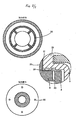
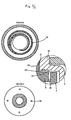
- Fig. 2 / 1 and 2.2 the area of the vents in the bottom of the blow-off electrode 3 and the inner 8 and the outer cup 9 is shown.
- This venting is realized via spiral grooves, in addition or instead of such spiral grooves ( Fig. 1 ), as in the illustrations Fig. 2 / 1 and 2.2 illustrated, a plurality of holes in the bottom of the inner cup 8 (section A) can be introduced. Through these holes 30 gas and melt reaches the bottom of the outer cup 9, which has a circumferential groove 32 with respect to the holes offset channels or a multiply fed spiral (section B / reference numeral 32).
- the support ring 7 is made of stainless steel in the embodiment shown and can take over the function of the potential control.
- the centering bodies 4 and 5 embed the main electrode 2, the centering body 5 forming the insulating flashover gap.
- the sleeve or disc 6 represents the conductive or semiconductive gas donating rollover stretch portion, wherein the support ring 7 carries the sleeve or disc 6.
Landscapes
- Plasma Technology (AREA)
- Shielding Devices Or Components To Electric Or Magnetic Fields (AREA)
- Casings For Electric Apparatus (AREA)
Claims (9)
- Éclateur à haute puissance, encapsulé, résistant à la pression, étanche mais non hermétique et à symétrie de révolution, comprenant deux électrodes principales opposées écartées, un boîtier extérieur métallique, une chambre de refroidissement de gaz ou de plasma entourée par le boîtier extérieur, ainsi que des contacts de raccordement électrique agencés de préférence du côté frontal pour les électrodes principales, caractérisé en ce que- la chambre de refroidissement est formée par un agencement coaxial d'un godet intérieur (8) et d'un godet extérieur (9), et l'une des électrodes principales est réalisée sous forme d'une électrode (3) de soufflage cylindrique creuse et s'étend jusque dans le godet intérieur (8),- il est en outre prévu sur le côté ouvert de l'agencement de godet une bague de soutien (7) à effet de centrage qui entoure latéralement l'électrode (3) de soufflage, et la bague de soutien (7) est reliée au godet extérieur (9) de manière à résister à la pression au moyen d'un vissage,- le godet extérieur (9) possède des ouvertures de sortie de gaz (10) latérales qui se trouvent dans des gorges (11), et il est prévu au moins un premier canal de refroidissement de gaz (12) entre le godet intérieur et le godet extérieur (8 ; 9), et il existe un autre second canal de refroidissement de gaz (13) entre la paroi extérieure du godet extérieur (9) et la paroi intérieure du boîtier extérieur (1).
- Éclateur selon la revendication 1,
caractérisé en ce que, dans la région de la face inférieure de l'électrode (3) de soufflage entre le godet intérieur (8) et un prolongement de guidage (14) il existe au moins un canal de refroidissement de gaz (15), qui s'étend jusque dans une ouverture à pas de vis (16) du godet intérieur (8), qui forme un contact de raccordement (17), et une gorge spiralée (18) est ménagée dans le fond extérieur de l'électrode (3) de soufflage pour le guidage du gaz. - Éclateur selon l'une des revendications précédentes,
caractérisé en ce que chaque godet (8 ; 9) de l'agencement coaxial possède une pipe annulaire circulaire (25 ; 26), et la pipe annulaire circulaire (25) du godet intérieur (8) est montée dans la pipe annulaire circulaire (26) du godet extérieur (9) et s'applique dans la région de la pipe annulaire circulaire (26) du godet extérieur (9) à coopération de formes contre le boîtier extérieur (1). - Éclateur selon l'une des revendications précédentes,
caractérisé en ce qu'une douille ou un disque (6) en un matériau d'apport de gaz conducteur ou semi-conducteur est agencé(e) entre les électrodes principales (2 ; 3). - Éclateur selon la revendication 4,
caractérisé en ce que sur le côté, détourné de l'électrode de soufflage, de la douille ou du disque (6) en matériau d'apport de gaz, il est prévu un corps de centrage et d'isolation (5) retroussé. - Éclateur selon la revendication 5,
caractérisé en ce que l'autre électrode principale (2) opposée à l'électrode de soufflage (3) est réalisée comme un disque (27) avec un prolongement de guidage (28). - Éclateur selon la revendication 6,
caractérisé en ce qu'il est prévu un autre corps de centrage et d'isolation (4) retroussé, et celui-ci est posé sur le prolongement de guidage (28) de l'autre électrode principale 2), et le corps isolant (4) entoure latéralement le disque (27) de l'électrode principale (2) et un talon périphérique du premier corps d'isolation et de centrage (5). - Éclateur selon la revendication 3,
caractérisé en ce que des perçages ou des gorges (30) pour le guidage des gaz sont ménagés dans la région de la face inférieure extérieure du godet intérieur (8), et il est prévu une fente (31) entre les pipes annulaires circulaires (25 ; 26). - Éclateur selon la revendication 8,
caractérisé en ce que des perçages ou des gorges (32) destiné(e)s au guidage des gaz sont ménagé(e)s dans la région de la face inférieure intérieure du godet extérieur (9), lesquel(le)s mènent à la fente (31).
Applications Claiming Priority (2)
| Application Number | Priority Date | Filing Date | Title |
|---|---|---|---|
| DE102006048977.2A DE102006048977B4 (de) | 2005-05-30 | 2006-10-17 | Gekapselte, druckfest ausgeführte, nicht hermetisch dichte, rotationssymmetrische Hochleistungsfunkenstrecke |
| PCT/EP2006/068747 WO2008046454A1 (fr) | 2006-10-17 | 2006-11-22 | éclateur à haute puissance, encapsulé, résistant à la pression, étanche mais non hermétique et à symétrie de rotation |
Publications (2)
| Publication Number | Publication Date |
|---|---|
| EP2080253A1 EP2080253A1 (fr) | 2009-07-22 |
| EP2080253B1 true EP2080253B1 (fr) | 2010-10-13 |
Family
ID=38042911
Family Applications (1)
| Application Number | Title | Priority Date | Filing Date |
|---|---|---|---|
| EP06819662A Not-in-force EP2080253B1 (fr) | 2006-10-17 | 2006-11-22 | Eclateur a haute puissance, encapsule, resistant a la pression, etanche mais non hermetique et a symetrie de rotation |
Country Status (5)
| Country | Link |
|---|---|
| EP (1) | EP2080253B1 (fr) |
| CN (1) | CN101529677B (fr) |
| AT (1) | ATE484867T1 (fr) |
| DE (1) | DE502006008106D1 (fr) |
| WO (1) | WO2008046454A1 (fr) |
Families Citing this family (1)
| Publication number | Priority date | Publication date | Assignee | Title |
|---|---|---|---|---|
| CN102738707B (zh) * | 2011-04-15 | 2014-07-23 | 上海电科电器科技有限公司 | 过电压保护装置 |
Family Cites Families (9)
| Publication number | Priority date | Publication date | Assignee | Title |
|---|---|---|---|---|
| DE2934237C2 (de) * | 1979-08-24 | 1983-02-17 | Aeg-Telefunken Ag, 1000 Berlin Und 6000 Frankfurt | Überspannungsableiter |
| DE19506057B4 (de) * | 1995-02-22 | 2004-07-22 | Dehn + Söhne GmbH + Co KG | Löschfunkenstreckenanordnung |
| DE19845889B4 (de) * | 1998-10-06 | 2007-03-01 | Dehn + Söhne GmbH + Co KG | Funkenstreckenanordnung |
| DE10008764A1 (de) * | 1999-03-04 | 2000-09-28 | Phoenix Contact Gmbh & Co | Überspannungsschutzeinrichtung |
| DE10018012B4 (de) * | 2000-02-22 | 2005-02-24 | Dehn + Söhne Gmbh + Co. Kg | Druckfest gekapselte Funkenstreckenanordnung zum Ableiten von schädlichen Störgrößen durch Überspannungen |
| DE10164025B4 (de) * | 2001-08-21 | 2005-08-25 | Dehn + Söhne Gmbh + Co. Kg | Gekapselter, Netzfolgestrom begrenzender Überspannungsableiter auf Funkenstreckenbasis |
| DE10338835B4 (de) * | 2003-08-21 | 2016-06-02 | Phoenix Contact Gmbh & Co. Kg | Überspannungsschutzeinrichtung |
| DE202004020260U1 (de) * | 2004-12-28 | 2005-02-24 | Phoenix Contact Gmbh & Co. Kg | Überspannungsschutzeinrichtung |
| DE102005024658B4 (de) * | 2005-05-30 | 2007-02-15 | Dehn + Söhne Gmbh + Co. Kg | Gekapselte, druckfest ausgeführte, nicht hermetisch dichte, rotationssymmetrische Hochleistungsfunkenstrecke |
-
2006
- 2006-11-22 EP EP06819662A patent/EP2080253B1/fr not_active Not-in-force
- 2006-11-22 WO PCT/EP2006/068747 patent/WO2008046454A1/fr not_active Ceased
- 2006-11-22 AT AT06819662T patent/ATE484867T1/de active
- 2006-11-22 DE DE502006008106T patent/DE502006008106D1/de active Active
- 2006-11-22 CN CN200680056157XA patent/CN101529677B/zh not_active Expired - Fee Related
Also Published As
| Publication number | Publication date |
|---|---|
| CN101529677B (zh) | 2012-01-04 |
| ATE484867T1 (de) | 2010-10-15 |
| CN101529677A (zh) | 2009-09-09 |
| DE502006008106D1 (de) | 2010-11-25 |
| EP2080253A1 (fr) | 2009-07-22 |
| WO2008046454A1 (fr) | 2008-04-24 |
Similar Documents
| Publication | Publication Date | Title |
|---|---|---|
| EP1911134B1 (fr) | Eclateur | |
| DE19717802B4 (de) | Funkenstrecke | |
| EP1747608B1 (fr) | Eclateur a haute performance encapsule, resistant a la pression, d'etancheite non hermetique et a symetrie de rotation | |
| EP3479391A1 (fr) | Dispositif de mise en court-circuit destiné à être utilisé dans des systèmes à basses et moyennes tensions pour la protection des biens et des personnes | |
| DE10164025B4 (de) | Gekapselter, Netzfolgestrom begrenzender Überspannungsableiter auf Funkenstreckenbasis | |
| EP2997587B1 (fr) | Disjoncteur | |
| DE102007002429B4 (de) | Gekapselter, druckfest ausgeführter blitzstromtragfähiger Überspannungsableiter mit Netzfolgestromlöschvermögen | |
| EP2080253B1 (fr) | Eclateur a haute puissance, encapsule, resistant a la pression, etanche mais non hermetique et a symetrie de rotation | |
| DE102008038486A1 (de) | Überspannungsschutzeinrichtung | |
| DE102014015611B4 (de) | Überspannungsableiter | |
| DE102006048977B4 (de) | Gekapselte, druckfest ausgeführte, nicht hermetisch dichte, rotationssymmetrische Hochleistungsfunkenstrecke | |
| DE10118210B4 (de) | Gekapselter Überspannungsableiter mit einer Funkenstreckenanordnung | |
| DE102014104576B4 (de) | Überspannungsableiter | |
| EP1961088B1 (fr) | Éclateur à haute puissance, étanche de manière non hermétique, encapsulé et résistant à la pression | |
| DE102007015931A1 (de) | Gekapselte, druckfest ausgeführte, nicht hermetisch dichte, rotationssymmetrische Hochleistungsfunkenstrecke | |
| DE102014015610B4 (de) | Überspannungsableiter | |
| EP2106629A1 (fr) | Éclateur à haute puissance à symétrie de rotation, non hermétiquement étanche, encapsulé et résistant à la pression | |
| EP1833130B1 (fr) | Dérivateur de surtensions encapsulé | |
| DE102014015612B4 (de) | Überspannungsableiter | |
| DE102015115550B4 (de) | Überspannungsableiter | |
| DE102014015609B3 (de) | Überspannungsableiter | |
| EP1992051A1 (fr) | Eclateur a haute puissance encapsule, resistant a la pression, ferme non hermetiquement, a la construction de base a symetrie rotationnelle | |
| DE10120563A1 (de) | Überspannungsschutzelement und Überspannungsschutzeinrichtung |
Legal Events
| Date | Code | Title | Description |
|---|---|---|---|
| PUAI | Public reference made under article 153(3) epc to a published international application that has entered the european phase |
Free format text: ORIGINAL CODE: 0009012 |
|
| 17P | Request for examination filed |
Effective date: 20070727 |
|
| AK | Designated contracting states |
Kind code of ref document: A1 Designated state(s): AT BE BG CH CY CZ DE DK EE ES FI FR GB GR HU IE IS IT LI LT LU LV MC NL PL PT RO SE SI SK TR |
|
| RIN1 | Information on inventor provided before grant (corrected) |
Inventor name: STRANGFELD, UWE Inventor name: EHRHARDT, ARND Inventor name: WAFFLER, MICHAEL Inventor name: HIERL, STEPHAN |
|
| GRAP | Despatch of communication of intention to grant a patent |
Free format text: ORIGINAL CODE: EPIDOSNIGR1 |
|
| GRAS | Grant fee paid |
Free format text: ORIGINAL CODE: EPIDOSNIGR3 |
|
| GRAA | (expected) grant |
Free format text: ORIGINAL CODE: 0009210 |
|
| AK | Designated contracting states |
Kind code of ref document: B1 Designated state(s): AT BE BG CH CY CZ DE DK EE ES FI FR GB GR HU IE IS IT LI LT LU LV MC NL PL PT RO SE SI SK TR |
|
| REG | Reference to a national code |
Ref country code: GB Ref legal event code: FG4D Free format text: NOT ENGLISH |
|
| REG | Reference to a national code |
Ref country code: CH Ref legal event code: EP |
|
| REG | Reference to a national code |
Ref country code: IE Ref legal event code: FG4D Free format text: LANGUAGE OF EP DOCUMENT: GERMAN |
|
| REF | Corresponds to: |
Ref document number: 502006008106 Country of ref document: DE Date of ref document: 20101125 Kind code of ref document: P |
|
| REG | Reference to a national code |
Ref country code: NL Ref legal event code: VDEP Effective date: 20101013 |
|
| LTIE | Lt: invalidation of european patent or patent extension |
Effective date: 20101013 |
|
| PG25 | Lapsed in a contracting state [announced via postgrant information from national office to epo] |
Ref country code: LT Free format text: LAPSE BECAUSE OF FAILURE TO SUBMIT A TRANSLATION OF THE DESCRIPTION OR TO PAY THE FEE WITHIN THE PRESCRIBED TIME-LIMIT Effective date: 20101013 |
|
| REG | Reference to a national code |
Ref country code: IE Ref legal event code: FD4D |
|
| BERE | Be: lapsed |
Owner name: DEHN + SOHNE G.M.B.H. + CO. KG Effective date: 20101130 |
|
| PG25 | Lapsed in a contracting state [announced via postgrant information from national office to epo] |
Ref country code: LV Free format text: LAPSE BECAUSE OF FAILURE TO SUBMIT A TRANSLATION OF THE DESCRIPTION OR TO PAY THE FEE WITHIN THE PRESCRIBED TIME-LIMIT Effective date: 20101013 Ref country code: FI Free format text: LAPSE BECAUSE OF FAILURE TO SUBMIT A TRANSLATION OF THE DESCRIPTION OR TO PAY THE FEE WITHIN THE PRESCRIBED TIME-LIMIT Effective date: 20101013 Ref country code: SE Free format text: LAPSE BECAUSE OF FAILURE TO SUBMIT A TRANSLATION OF THE DESCRIPTION OR TO PAY THE FEE WITHIN THE PRESCRIBED TIME-LIMIT Effective date: 20101013 Ref country code: PT Free format text: LAPSE BECAUSE OF FAILURE TO SUBMIT A TRANSLATION OF THE DESCRIPTION OR TO PAY THE FEE WITHIN THE PRESCRIBED TIME-LIMIT Effective date: 20110214 Ref country code: IS Free format text: LAPSE BECAUSE OF FAILURE TO SUBMIT A TRANSLATION OF THE DESCRIPTION OR TO PAY THE FEE WITHIN THE PRESCRIBED TIME-LIMIT Effective date: 20110213 Ref country code: NL Free format text: LAPSE BECAUSE OF FAILURE TO SUBMIT A TRANSLATION OF THE DESCRIPTION OR TO PAY THE FEE WITHIN THE PRESCRIBED TIME-LIMIT Effective date: 20101013 Ref country code: SI Free format text: LAPSE BECAUSE OF FAILURE TO SUBMIT A TRANSLATION OF THE DESCRIPTION OR TO PAY THE FEE WITHIN THE PRESCRIBED TIME-LIMIT Effective date: 20101013 Ref country code: BG Free format text: LAPSE BECAUSE OF FAILURE TO SUBMIT A TRANSLATION OF THE DESCRIPTION OR TO PAY THE FEE WITHIN THE PRESCRIBED TIME-LIMIT Effective date: 20110113 |
|
| PG25 | Lapsed in a contracting state [announced via postgrant information from national office to epo] |
Ref country code: MC Free format text: LAPSE BECAUSE OF NON-PAYMENT OF DUE FEES Effective date: 20101130 Ref country code: GR Free format text: LAPSE BECAUSE OF FAILURE TO SUBMIT A TRANSLATION OF THE DESCRIPTION OR TO PAY THE FEE WITHIN THE PRESCRIBED TIME-LIMIT Effective date: 20110114 |
|
| REG | Reference to a national code |
Ref country code: CH Ref legal event code: PL |
|
| PG25 | Lapsed in a contracting state [announced via postgrant information from national office to epo] |
Ref country code: IE Free format text: LAPSE BECAUSE OF FAILURE TO SUBMIT A TRANSLATION OF THE DESCRIPTION OR TO PAY THE FEE WITHIN THE PRESCRIBED TIME-LIMIT Effective date: 20101013 Ref country code: LI Free format text: LAPSE BECAUSE OF NON-PAYMENT OF DUE FEES Effective date: 20101130 Ref country code: ES Free format text: LAPSE BECAUSE OF FAILURE TO SUBMIT A TRANSLATION OF THE DESCRIPTION OR TO PAY THE FEE WITHIN THE PRESCRIBED TIME-LIMIT Effective date: 20110124 Ref country code: EE Free format text: LAPSE BECAUSE OF FAILURE TO SUBMIT A TRANSLATION OF THE DESCRIPTION OR TO PAY THE FEE WITHIN THE PRESCRIBED TIME-LIMIT Effective date: 20101013 Ref country code: CH Free format text: LAPSE BECAUSE OF NON-PAYMENT OF DUE FEES Effective date: 20101130 Ref country code: CZ Free format text: LAPSE BECAUSE OF FAILURE TO SUBMIT A TRANSLATION OF THE DESCRIPTION OR TO PAY THE FEE WITHIN THE PRESCRIBED TIME-LIMIT Effective date: 20101013 |
|
| PLBE | No opposition filed within time limit |
Free format text: ORIGINAL CODE: 0009261 |
|
| STAA | Information on the status of an ep patent application or granted ep patent |
Free format text: STATUS: NO OPPOSITION FILED WITHIN TIME LIMIT |
|
| PG25 | Lapsed in a contracting state [announced via postgrant information from national office to epo] |
Ref country code: BE Free format text: LAPSE BECAUSE OF NON-PAYMENT OF DUE FEES Effective date: 20101130 Ref country code: PL Free format text: LAPSE BECAUSE OF FAILURE TO SUBMIT A TRANSLATION OF THE DESCRIPTION OR TO PAY THE FEE WITHIN THE PRESCRIBED TIME-LIMIT Effective date: 20101013 Ref country code: SK Free format text: LAPSE BECAUSE OF FAILURE TO SUBMIT A TRANSLATION OF THE DESCRIPTION OR TO PAY THE FEE WITHIN THE PRESCRIBED TIME-LIMIT Effective date: 20101013 Ref country code: RO Free format text: LAPSE BECAUSE OF FAILURE TO SUBMIT A TRANSLATION OF THE DESCRIPTION OR TO PAY THE FEE WITHIN THE PRESCRIBED TIME-LIMIT Effective date: 20101013 Ref country code: DK Free format text: LAPSE BECAUSE OF FAILURE TO SUBMIT A TRANSLATION OF THE DESCRIPTION OR TO PAY THE FEE WITHIN THE PRESCRIBED TIME-LIMIT Effective date: 20101013 |
|
| 26N | No opposition filed |
Effective date: 20110714 |
|
| GBPC | Gb: european patent ceased through non-payment of renewal fee |
Effective date: 20110113 |
|
| REG | Reference to a national code |
Ref country code: DE Ref legal event code: R097 Ref document number: 502006008106 Country of ref document: DE Effective date: 20110714 |
|
| PG25 | Lapsed in a contracting state [announced via postgrant information from national office to epo] |
Ref country code: GB Free format text: LAPSE BECAUSE OF NON-PAYMENT OF DUE FEES Effective date: 20110113 |
|
| PG25 | Lapsed in a contracting state [announced via postgrant information from national office to epo] |
Ref country code: IT Free format text: LAPSE BECAUSE OF FAILURE TO SUBMIT A TRANSLATION OF THE DESCRIPTION OR TO PAY THE FEE WITHIN THE PRESCRIBED TIME-LIMIT Effective date: 20101013 |
|
| PG25 | Lapsed in a contracting state [announced via postgrant information from national office to epo] |
Ref country code: CY Free format text: LAPSE BECAUSE OF FAILURE TO SUBMIT A TRANSLATION OF THE DESCRIPTION OR TO PAY THE FEE WITHIN THE PRESCRIBED TIME-LIMIT Effective date: 20101013 |
|
| PG25 | Lapsed in a contracting state [announced via postgrant information from national office to epo] |
Ref country code: HU Free format text: LAPSE BECAUSE OF FAILURE TO SUBMIT A TRANSLATION OF THE DESCRIPTION OR TO PAY THE FEE WITHIN THE PRESCRIBED TIME-LIMIT Effective date: 20110414 Ref country code: LU Free format text: LAPSE BECAUSE OF NON-PAYMENT OF DUE FEES Effective date: 20101122 |
|
| PG25 | Lapsed in a contracting state [announced via postgrant information from national office to epo] |
Ref country code: TR Free format text: LAPSE BECAUSE OF FAILURE TO SUBMIT A TRANSLATION OF THE DESCRIPTION OR TO PAY THE FEE WITHIN THE PRESCRIBED TIME-LIMIT Effective date: 20101013 |
|
| REG | Reference to a national code |
Ref country code: AT Ref legal event code: MM01 Ref document number: 484867 Country of ref document: AT Kind code of ref document: T Effective date: 20111122 |
|
| PG25 | Lapsed in a contracting state [announced via postgrant information from national office to epo] |
Ref country code: AT Free format text: LAPSE BECAUSE OF NON-PAYMENT OF DUE FEES Effective date: 20111122 |
|
| PGFP | Annual fee paid to national office [announced via postgrant information from national office to epo] |
Ref country code: FR Payment date: 20141128 Year of fee payment: 9 |
|
| REG | Reference to a national code |
Ref country code: FR Ref legal event code: ST Effective date: 20160729 |
|
| PG25 | Lapsed in a contracting state [announced via postgrant information from national office to epo] |
Ref country code: FR Free format text: LAPSE BECAUSE OF NON-PAYMENT OF DUE FEES Effective date: 20151130 |
|
| REG | Reference to a national code |
Ref country code: DE Ref legal event code: R081 Ref document number: 502006008106 Country of ref document: DE Owner name: DEHN SE, DE Free format text: FORMER OWNER: DEHN + SOEHNE GMBH + CO. KG, 92318 NEUMARKT, DE Ref country code: DE Ref legal event code: R082 Ref document number: 502006008106 Country of ref document: DE Representative=s name: MEISSNER BOLTE PATENTANWAELTE RECHTSANWAELTE P, DE Ref country code: DE Ref legal event code: R081 Ref document number: 502006008106 Country of ref document: DE Owner name: DEHN SE + CO KG, DE Free format text: FORMER OWNER: DEHN + SOEHNE GMBH + CO. KG, 92318 NEUMARKT, DE Ref country code: DE Ref legal event code: R082 Ref document number: 502006008106 Country of ref document: DE Representative=s name: ISARPATENT - PATENT- UND RECHTSANWAELTE BARTH , DE |
|
| REG | Reference to a national code |
Ref country code: DE Ref legal event code: R082 Ref document number: 502006008106 Country of ref document: DE Representative=s name: ISARPATENT - PATENT- UND RECHTSANWAELTE BARTH , DE |
|
| PGFP | Annual fee paid to national office [announced via postgrant information from national office to epo] |
Ref country code: DE Payment date: 20211122 Year of fee payment: 16 |
|
| REG | Reference to a national code |
Ref country code: DE Ref legal event code: R081 Ref document number: 502006008106 Country of ref document: DE Owner name: DEHN SE, DE Free format text: FORMER OWNER: DEHN SE + CO KG, 92318 NEUMARKT, DE |
|
| REG | Reference to a national code |
Ref country code: DE Ref legal event code: R119 Ref document number: 502006008106 Country of ref document: DE |
|
| PG25 | Lapsed in a contracting state [announced via postgrant information from national office to epo] |
Ref country code: DE Free format text: LAPSE BECAUSE OF NON-PAYMENT OF DUE FEES Effective date: 20230601 |