EP2080451A2 - Accoudoir pivotant pour un siège et siège doté d'un accoudoir pivotant - Google Patents
Accoudoir pivotant pour un siège et siège doté d'un accoudoir pivotant Download PDFInfo
- Publication number
- EP2080451A2 EP2080451A2 EP09150056A EP09150056A EP2080451A2 EP 2080451 A2 EP2080451 A2 EP 2080451A2 EP 09150056 A EP09150056 A EP 09150056A EP 09150056 A EP09150056 A EP 09150056A EP 2080451 A2 EP2080451 A2 EP 2080451A2
- Authority
- EP
- European Patent Office
- Prior art keywords
- chair
- armrest
- pivotable
- locking
- pivoting
- Prior art date
- Legal status (The legal status is an assumption and is not a legal conclusion. Google has not performed a legal analysis and makes no representation as to the accuracy of the status listed.)
- Granted
Links
Images


Classifications
-
- A—HUMAN NECESSITIES
- A61—MEDICAL OR VETERINARY SCIENCE; HYGIENE
- A61G—TRANSPORT, PERSONAL CONVEYANCES OR ACCOMMODATION SPECIALLY ADAPTED FOR PATIENTS OR DISABLED PERSONS; OPERATING TABLES OR CHAIRS; CHAIRS FOR DENTISTRY; FUNERAL DEVICES
- A61G5/00—Chairs or personal conveyances specially adapted for patients or disabled persons, e.g. wheelchairs
- A61G5/10—Parts, details or accessories
- A61G5/12—Rests specially adapted therefor, e.g. for the head or the feet
-
- A—HUMAN NECESSITIES
- A47—FURNITURE; DOMESTIC ARTICLES OR APPLIANCES; COFFEE MILLS; SPICE MILLS; SUCTION CLEANERS IN GENERAL
- A47C—CHAIRS; SOFAS; BEDS
- A47C1/00—Chairs adapted for special purposes
- A47C1/02—Reclining or easy chairs
- A47C1/022—Reclining or easy chairs having independently-adjustable supporting parts
- A47C1/03—Reclining or easy chairs having independently-adjustable supporting parts the parts being arm-rests
- A47C1/0308—Reclining or easy chairs having independently-adjustable supporting parts the parts being arm-rests adjustable by rotation
-
- A—HUMAN NECESSITIES
- A61—MEDICAL OR VETERINARY SCIENCE; HYGIENE
- A61G—TRANSPORT, PERSONAL CONVEYANCES OR ACCOMMODATION SPECIALLY ADAPTED FOR PATIENTS OR DISABLED PERSONS; OPERATING TABLES OR CHAIRS; CHAIRS FOR DENTISTRY; FUNERAL DEVICES
- A61G5/00—Chairs or personal conveyances specially adapted for patients or disabled persons, e.g. wheelchairs
- A61G5/10—Parts, details or accessories
- A61G5/12—Rests specially adapted therefor, e.g. for the head or the feet
- A61G5/125—Rests specially adapted therefor, e.g. for the head or the feet for arms
Definitions
- the invention relates to a pivotable backrest for a chair and a chair with swivel armrest, in particular a hospital chair, for example a shower wheelchair, as it is known under the product name Flexo by the company Invacare.
- Armrests are naturally attached to the sides of a chair.
- the front ends of such armrests are often inwardly bent, particularly in sick chairs, to ensure that the person sitting in the chair can not fall forward.
- Even with substantially straight running armrests are sometimes provided to the center of the chair extending attachments, such as writing pads in school chairs or chairs for lecture halls.
- backrests of the type in question are arranged pivotably.
- they can be pivoted in a substantially vertical direction relative to the chair.
- the armrest has a pivotable part, which is articulated pivotably on the chair, preferably in a substantially vertical direction, so that a folding up of the armrest is made possible.
- a chair is for example from the JP 2005-556 A known.
- An end extending from the armrest towards the middle of the chair or a corresponding attachment, for example in the form of a book rest, can likewise often be folded up in the case of such chairs.
- This rotatable part can for example be a bent end of the armrest itself or else another component to which a component extending towards the center of the chair is attached. If now this rotatable part of the armrest is rotated relative to the pivotable part, the part of the armrest extending towards the middle or the relevant attachment part likewise pivots, preferably upwards, in order thus likewise to facilitate access to the chair.
- the invention has for its object to perform an armrest of the type in question or such a chair so that injuries when operating the armrest can be avoided.
- the armrest according to the invention is attached to a chair, such as a hospital chair, pivotally mounted. It has a relative to the chair pivotable part and a rotatable part which is rotatable relative to the pivotable part. For pivotal mounting of the pivotable part of the chair, a bearing element is provided.
- the pivotable armrest according to the invention has a locking element that is designed so that the pivotable part of the armrest is pivotable relative to the chair only when the rotatable part of the armrest with respect to the pivotable part assumes a defined predetermined position.
- a defined predetermined position is in particular such a position in which does not occupy a position during vertical pivoting of the pivotable part of the rotatable part, which could endanger or injure a person sitting in the chair.
- a coupling shaft is preferably provided with a polygon.
- this polygon is designed as a square.
- the polygon designed for example as a square, cooperates with a correspondingly executed recess of a locking disk.
- the number of edges thus determines the number of positions in which the rotatable part of the armrest can be fixed.
- the rotatable part of the armrest can thus occupy four defined positions relative to the pivotable part.
- pivoting of the pivotable part of the armrest is only possible in one of these four positions of the rotatable part.
- the rotatable part of the armrest is preferably fixedly connected to the locking disk.
- the blocking element preferably has a locking pin which projects into a bore of a chair-side pivot bearing element in a locking position which prevents pivoting.
- a chair-side pivot bearing element may be executed in an armrest according to the invention, which is designed as a separately tradable goods, for attachment to any chair.
- a chair-side pivot bearing element may already be fixed.
- the blocking element embodied for example as a coupling shaft
- the blocking element can be displaceably mounted within the pivotable part of the armrest and be biased by means of a compression spring in the direction of the locking disk.
- the displacement of the locking element or the coupling shaft can take place via an outer protective sleeve.
- the blocking element or the coupling shaft can be moved counter to the force of the compression spring, so that the example executed as a square polygon emerges from the recess of the locking disc.
- the fixedly connected to the locking disk rotatable part of the armrest can be rotated in this position of the locking element and, once he has reached one of the predefined possible positions, are fixed in this position by the outer protective sleeve released and thus the blocking element or the coupling shaft through the Force of the compression spring is moved back in the direction of the locking disc, so that the example executed as a square polygon enters the recess of the locking disc and fixes the relevant position of the rotatable part of the armrest.
- the blocking element or the coupling shaft may have a bore for receiving a cylindrical pin.
- This cylinder pin allows a partial penetration of the polygon of the coupling shaft, which is designed as a square, for example, into the recess of the locking disk only in a predetermined position. In this position, in which the cylinder pin can penetrate into a correspondingly executed recess of the locking disk, the polygon penetrates almost completely into the recess of the locking disk.
- This arrangement causes only in this one position, in which the blocking element is moved completely in the direction of the locking disk, the locking pin from the bore of the chair-side pivot bearing element emerges. Only in this one position of the rotatable part of the armrest relative to the pivotal part of the armrest thus pivoting of the pivotable part of the armrest relative to the chair is possible.
- the described components can also be designed so that a pivoting of the pivotable part of the armrest relative to the chair in a plurality of predetermined positions of the rotatable part of the armrest relative to the pivotable part of the armrest is possible. It is also understood that not only four, but also almost any other number of predetermined positions of the rotatable part of the armrests relative to the pivotable part of the armrest are possible. For example, if six defined positions are provided, the polygon is designed accordingly as a hexagon.
- two corresponding recesses could be formed in the locking disc, so that in two predetermined positions of the hexagon running in this case, the full-length completely into the recess of the locking disc, which would be executed in this case according to the hexagon, penetrate, which thereby would allow two recesses would be formed in the end face of the locking disk, so that the cylinder pin can penetrate into two positions in the respective wells.
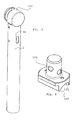
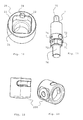
- Fig. 8 shows a chair-side pivot bearing member 100 that can be attached with a recess 101 on a tubular chair element (not shown). It is understood that a functionally identical element can be attached directly to a chair.
- vertical and horizontal refer to a conventional position of a chair on a horizontal floor.
- the chair-side pivot bearing member 100 cooperates with a armrest-side bearing housing 200, which in the FIGS. 12 and 13 is shown.
- the armrest-side bearing housing 200 is attached to a first end of a pivotable part 2 of the armrest.
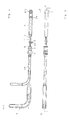
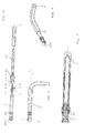
- the pivotable part 2 of the armrest is substantially tubular and has a slot 2a (see, eg Fig. 6 ).
- a compression spring 3 and a coupling shaft 7 are inserted in the tube interior of the pivotable part 2, a compression spring 3 and a coupling shaft 7 are inserted.
- the coupling shaft 7 (see Fig. 11 ) has a bore 73 through which an actuating pin 8 can be guided, which is held by a screwed into a threaded bore 74 of the coupling shaft 7 threaded pin 10.
- the coupling shaft 7 further has a locking pin 75, which is insertable into a bore 102 of the chair-side pivot bearing element 100, and a guide pin 76 which is in engagement with a guide 21 of
- the locking disk 20 ( Fig. 10 ) is fixedly connected to a rotatable part 40 of the armrest.
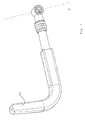
- the rotatable part 40 of the armrest is in Fig. 14 shown as a component which consists of a bent pipe section and two adjoining straight pipe sections. This component may be surrounded by a foam shell 5, as in the Fig. 1 to 6 shown. It is understood that the rotatable part can also consist of any other component which is rotatable relative to the pivotable part 2 and depending on the intended use corresponding attachments.
- a reinforcing sleeve 6 On the pivotable part 2, a reinforcing sleeve 6 is attached, which has two slots 2a of the pivotable part 2 corresponding slots 6a.
- a protective sleeve 4 On the reinforcing sleeve 6, a protective sleeve 4 is slidably disposed.
- the protective sleeve 4 has two holes 4a, which are provided for receiving the actuating bolt 8.
- the actuating bolt 8 connects the protective sleeve 4 with the coupling shaft 7, so that the coupling shaft 7 can be moved from the outside by means of the protective sleeve 4 within the pivotable part 2 in the limits of the slots 2a and 6a.
- the rotatable member 40 has a right angle angled extension part 41 which extends perpendicular to the rotation axis of the rotatable member 40.
- the recess 22 of the locking disc 20 for receiving the square 71 of the coupling shaft 7 is arranged with respect to the rotatable member 40 so that two longitudinal sides of the recess 22 substantially square with rounded corners extend in the direction of the extension 41.
- the coupling shaft 7 is in connection with the actuating pin 8 and the slots 2a and 6a with respect to the position of the square 71 to the pivotal part 2 and thus fixedly arranged on the dm pivotable part 2, for example, welded armrests side layer housing 2 also in terms of the chair side Swivel bearing element 100 extending pivot axis set.
- the coupling shaft 7 can thus axially within the pivotable part 2 only over a certain range moved but not twisted.
- the end points of the axial displacement are determined via the actuating pin 8 by the dimensions of the slots 2a and 6a.
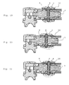
- the square 71 of the coupling shaft 7 is outside the recess 22 of the locking disk 20.
- the rotatable member 40 can thus be rotated relative to the pivotable member 20, so that the bent end 41 and the outer end 52 (FIGS. Fig. 1 ) can be pivoted.
- the locking pin 75 extends into the bore 102 of the chair-side pivot bearing element 100. A pivoting of the pivotable part of a chair (not shown) upwards is thus in this position the coupling shaft 7 not possible.
- the rotatable member 40 can be fixed in four defined rotational positions, each achieved by a rotation of 90 degrees. In three of these positions, the coupling shaft 7 with the square 71 does not penetrate completely into the recess 22 of the locking disk 2, since the cylinder pin 9 abuts against the end face 23 of the locking disk. Such a position of the coupling shaft 7 is in Fig. 19 shown. In such a position, the square 71 of the coupling shaft 7 is partially inserted into the recess 22 of the locking disk 20 and the locking pin 75 is partially inserted into the bore 102 of the chair-side pivot bearing member 100. This means that both a rotation of the rotatable part 40 and a pivoting of the pivotable part 2 is not possible.
- the arrangement is chosen so that this position corresponds to a position of the angled portion 41, which can not lead to a risk of injury of a person sitting in the chair person, for example, in the case of a pivoting of the armrest Fig. 1 shown position.
Landscapes
- Health & Medical Sciences (AREA)
- General Health & Medical Sciences (AREA)
- Dentistry (AREA)
- Life Sciences & Earth Sciences (AREA)
- Animal Behavior & Ethology (AREA)
- Public Health (AREA)
- Veterinary Medicine (AREA)
- Chair Legs, Seat Parts, And Backrests (AREA)
- Seats For Vehicles (AREA)
- Chairs For Special Purposes, Such As Reclining Chairs (AREA)
- Special Chairs (AREA)
Applications Claiming Priority (1)
| Application Number | Priority Date | Filing Date | Title |
|---|---|---|---|
| DE102008002752A DE102008002752B3 (de) | 2008-01-18 | 2008-01-18 | Schwenkbare Lehne für einen Stuhl und Stuhl mit schwenkbarer Armlehne |
Publications (3)
| Publication Number | Publication Date |
|---|---|
| EP2080451A2 true EP2080451A2 (fr) | 2009-07-22 |
| EP2080451A3 EP2080451A3 (fr) | 2010-04-28 |
| EP2080451B1 EP2080451B1 (fr) | 2011-12-28 |
Family
ID=40622287
Family Applications (1)
| Application Number | Title | Priority Date | Filing Date |
|---|---|---|---|
| EP09150056A Not-in-force EP2080451B1 (fr) | 2008-01-18 | 2009-01-05 | Accoudoir pivotant pour un siège et siège doté d'un accoudoir pivotant |
Country Status (4)
| Country | Link |
|---|---|
| EP (1) | EP2080451B1 (fr) |
| AT (1) | ATE538688T1 (fr) |
| DE (1) | DE102008002752B3 (fr) |
| DK (1) | DK2080451T3 (fr) |
Cited By (1)
| Publication number | Priority date | Publication date | Assignee | Title |
|---|---|---|---|---|
| GB2491828A (en) * | 2011-06-10 | 2012-12-19 | John Horrigan | Mounting device for wheelchair |
Citations (1)
| Publication number | Priority date | Publication date | Assignee | Title |
|---|---|---|---|---|
| JP2005000556A (ja) | 2003-06-13 | 2005-01-06 | Canon Semiconductor Equipment Inc | 椅子のアームレスト及びストレッチャのアームレスト |
Family Cites Families (6)
| Publication number | Priority date | Publication date | Assignee | Title |
|---|---|---|---|---|
| DE2050322A1 (de) * | 1970-10-14 | 1972-04-20 | Wilkhahn Wilkening & Hahne | Stuhl |
| JPH025556A (ja) * | 1988-06-24 | 1990-01-10 | Hitachi Ltd | Icソケット |
| JPH08308881A (ja) * | 1995-05-19 | 1996-11-26 | Atex Co Ltd | 車椅子のアームレスト |
| IT1302063B1 (it) * | 1998-02-25 | 2000-07-20 | Pro Cord Srl | Dispositivo di sopporto anti-panico per una tavoletta di sedia, esedia comprendente tale dispositivo. |
| NL1010437C1 (nl) * | 1998-10-30 | 2000-05-03 | Lopital Nederland B V | Rolstoel zoals in de vorm van een douche-stoel of dergelijke inrichting, voorzien van armleggers. |
| DE102005052487B4 (de) * | 2005-11-03 | 2007-09-13 | Greiner Gmbh | Stuhl, insbesondere Behandlungsstuhl |
-
2008
- 2008-01-18 DE DE102008002752A patent/DE102008002752B3/de not_active Expired - Fee Related
-
2009
- 2009-01-05 DK DK09150056.1T patent/DK2080451T3/da active
- 2009-01-05 EP EP09150056A patent/EP2080451B1/fr not_active Not-in-force
- 2009-01-05 AT AT09150056T patent/ATE538688T1/de active
Patent Citations (1)
| Publication number | Priority date | Publication date | Assignee | Title |
|---|---|---|---|---|
| JP2005000556A (ja) | 2003-06-13 | 2005-01-06 | Canon Semiconductor Equipment Inc | 椅子のアームレスト及びストレッチャのアームレスト |
Cited By (2)
| Publication number | Priority date | Publication date | Assignee | Title |
|---|---|---|---|---|
| GB2491828A (en) * | 2011-06-10 | 2012-12-19 | John Horrigan | Mounting device for wheelchair |
| GB2491828B (en) * | 2011-06-10 | 2016-08-24 | Horrigan John | A device |
Also Published As
| Publication number | Publication date |
|---|---|
| ATE538688T1 (de) | 2012-01-15 |
| DE102008002752B3 (de) | 2009-07-30 |
| EP2080451B1 (fr) | 2011-12-28 |
| EP2080451A3 (fr) | 2010-04-28 |
| DK2080451T3 (da) | 2012-04-23 |
Similar Documents
| Publication | Publication Date | Title |
|---|---|---|
| EP2962602B1 (fr) | Chaise | |
| EP2508102B1 (fr) | Chaise | |
| DE602004001378T2 (de) | Fahrzeugsitz. | |
| DE102004044970B4 (de) | Kopfstützenanordnung mit Nockenantrieb in vier Richtungen | |
| EP0842844B1 (fr) | Siège de véhicule | |
| DE3429186A1 (de) | Sitzmoebel, insbesondere buerostuhl | |
| DE102013000163A1 (de) | Sitzanordnung für ein Fahrzeug | |
| DE20302612U1 (de) | Liegestuhl | |
| DE102013104760B3 (de) | Fahrzeugsitz, insbesondere für ein Kraftfahrzeug | |
| DE102018100449B4 (de) | Sitzanordnung für ein Fahrzeug | |
| EP2084991A1 (fr) | Armature pivotante | |
| EP2818358A1 (fr) | Siège de véhicule et véhicule utilitaire doté d'un siège de véhicule | |
| DE102024002956A1 (de) | Displayanordnung für einen Kraftwagen sowie Kraftwagen mit einer Displayanordnung | |
| EP2080451B1 (fr) | Accoudoir pivotant pour un siège et siège doté d'un accoudoir pivotant | |
| DE19905001B4 (de) | Stuhl mit einer Armlehne und Vorrichtung zur Lagerung eines Tischchens an einer Armlehne | |
| EP3741255B1 (fr) | Ferrure pivotante et meuble | |
| DE10239199B4 (de) | Ausfahrbarer Sitz für ein Fahrzeug sowie Fahrzeug mit einem ausfahrbaren Sitz | |
| DE102006021439A1 (de) | Stuhl, insbesondere Bürostuhl und Gelenkvorrichtung für einen Stuhl | |
| DE202005020080U1 (de) | Sitzmöbel mit Rückenlehne und verstellbarer Kopfstütze | |
| DE102012104974A1 (de) | Vorrichtung zur Verstellung und Positionierung der Rückenlehnenneigung eines Sitzmöbels | |
| DE2932347B2 (de) | Schwenkbare Armstütze für einen Sitz, insbesondere Kraftfahrzeugsitz | |
| EP3893696B1 (fr) | Meuble pour s'asseoir comportant un dispositif d'appui dorsolombaire | |
| EP3248508A1 (fr) | Dispositif de siège | |
| EP0870476A1 (fr) | Chaise pour médecins | |
| DE19635635C1 (de) | Sitzmöbel |
Legal Events
| Date | Code | Title | Description |
|---|---|---|---|
| PUAI | Public reference made under article 153(3) epc to a published international application that has entered the european phase |
Free format text: ORIGINAL CODE: 0009012 |
|
| AK | Designated contracting states |
Kind code of ref document: A2 Designated state(s): AT BE BG CH CY CZ DE DK EE ES FI FR GB GR HR HU IE IS IT LI LT LU LV MC MK MT NL NO PL PT RO SE SI SK TR |
|
| AX | Request for extension of the european patent |
Extension state: AL BA RS |
|
| PUAL | Search report despatched |
Free format text: ORIGINAL CODE: 0009013 |
|
| AK | Designated contracting states |
Kind code of ref document: A3 Designated state(s): AT BE BG CH CY CZ DE DK EE ES FI FR GB GR HR HU IE IS IT LI LT LU LV MC MK MT NL NO PL PT RO SE SI SK TR |
|
| AX | Request for extension of the european patent |
Extension state: AL BA RS |
|
| RIC1 | Information provided on ipc code assigned before grant |
Ipc: A61F 5/37 20060101ALI20100323BHEP Ipc: A47C 7/54 20060101AFI20090518BHEP Ipc: A61G 5/12 20060101ALI20100323BHEP |
|
| 17P | Request for examination filed |
Effective date: 20101019 |
|
| 17Q | First examination report despatched |
Effective date: 20101124 |
|
| AKX | Designation fees paid |
Designated state(s): AT BE BG CH CY CZ DE DK EE ES FI FR GB GR HR HU IE IS IT LI LT LU LV MC MK MT NL NO PL PT RO SE SI SK TR |
|
| GRAP | Despatch of communication of intention to grant a patent |
Free format text: ORIGINAL CODE: EPIDOSNIGR1 |
|
| RIC1 | Information provided on ipc code assigned before grant |
Ipc: A61F 5/37 20060101ALI20110614BHEP Ipc: A47C 7/54 20060101AFI20110614BHEP Ipc: A61G 5/12 20060101ALI20110614BHEP |
|
| GRAS | Grant fee paid |
Free format text: ORIGINAL CODE: EPIDOSNIGR3 |
|
| GRAA | (expected) grant |
Free format text: ORIGINAL CODE: 0009210 |
|
| AK | Designated contracting states |
Kind code of ref document: B1 Designated state(s): AT BE BG CH CY CZ DE DK EE ES FI FR GB GR HR HU IE IS IT LI LT LU LV MC MK MT NL NO PL PT RO SE SI SK TR |
|
| REG | Reference to a national code |
Ref country code: GB Ref legal event code: FG4D Free format text: NOT ENGLISH |
|
| REG | Reference to a national code |
Ref country code: CH Ref legal event code: EP |
|
| REG | Reference to a national code |
Ref country code: AT Ref legal event code: REF Ref document number: 538688 Country of ref document: AT Kind code of ref document: T Effective date: 20120115 |
|
| REG | Reference to a national code |
Ref country code: IE Ref legal event code: FG4D |
|
| REG | Reference to a national code |
Ref country code: DE Ref legal event code: R096 Ref document number: 502009002284 Country of ref document: DE Effective date: 20120308 |
|
| REG | Reference to a national code |
Ref country code: SE Ref legal event code: TRGR |
|
| REG | Reference to a national code |
Ref country code: NL Ref legal event code: T3 |
|
| REG | Reference to a national code |
Ref country code: DK Ref legal event code: T3 |
|
| PG25 | Lapsed in a contracting state [announced via postgrant information from national office to epo] |
Ref country code: NO Free format text: LAPSE BECAUSE OF FAILURE TO SUBMIT A TRANSLATION OF THE DESCRIPTION OR TO PAY THE FEE WITHIN THE PRESCRIBED TIME-LIMIT Effective date: 20120328 Ref country code: LT Free format text: LAPSE BECAUSE OF FAILURE TO SUBMIT A TRANSLATION OF THE DESCRIPTION OR TO PAY THE FEE WITHIN THE PRESCRIBED TIME-LIMIT Effective date: 20111228 |
|
| LTIE | Lt: invalidation of european patent or patent extension |
Effective date: 20111228 |
|
| PG25 | Lapsed in a contracting state [announced via postgrant information from national office to epo] |
Ref country code: SI Free format text: LAPSE BECAUSE OF FAILURE TO SUBMIT A TRANSLATION OF THE DESCRIPTION OR TO PAY THE FEE WITHIN THE PRESCRIBED TIME-LIMIT Effective date: 20111228 Ref country code: GR Free format text: LAPSE BECAUSE OF FAILURE TO SUBMIT A TRANSLATION OF THE DESCRIPTION OR TO PAY THE FEE WITHIN THE PRESCRIBED TIME-LIMIT Effective date: 20120329 Ref country code: HR Free format text: LAPSE BECAUSE OF FAILURE TO SUBMIT A TRANSLATION OF THE DESCRIPTION OR TO PAY THE FEE WITHIN THE PRESCRIBED TIME-LIMIT Effective date: 20111228 Ref country code: LV Free format text: LAPSE BECAUSE OF FAILURE TO SUBMIT A TRANSLATION OF THE DESCRIPTION OR TO PAY THE FEE WITHIN THE PRESCRIBED TIME-LIMIT Effective date: 20111228 |
|
| PG25 | Lapsed in a contracting state [announced via postgrant information from national office to epo] |
Ref country code: CY Free format text: LAPSE BECAUSE OF FAILURE TO SUBMIT A TRANSLATION OF THE DESCRIPTION OR TO PAY THE FEE WITHIN THE PRESCRIBED TIME-LIMIT Effective date: 20111228 |
|
| REG | Reference to a national code |
Ref country code: IE Ref legal event code: FD4D |
|
| BERE | Be: lapsed |
Owner name: AQUATEC OPERATIONS G.M.B.H. Effective date: 20120131 |
|
| PG25 | Lapsed in a contracting state [announced via postgrant information from national office to epo] |
Ref country code: IS Free format text: LAPSE BECAUSE OF FAILURE TO SUBMIT A TRANSLATION OF THE DESCRIPTION OR TO PAY THE FEE WITHIN THE PRESCRIBED TIME-LIMIT Effective date: 20120428 Ref country code: SK Free format text: LAPSE BECAUSE OF FAILURE TO SUBMIT A TRANSLATION OF THE DESCRIPTION OR TO PAY THE FEE WITHIN THE PRESCRIBED TIME-LIMIT Effective date: 20111228 Ref country code: CZ Free format text: LAPSE BECAUSE OF FAILURE TO SUBMIT A TRANSLATION OF THE DESCRIPTION OR TO PAY THE FEE WITHIN THE PRESCRIBED TIME-LIMIT Effective date: 20111228 Ref country code: BG Free format text: LAPSE BECAUSE OF FAILURE TO SUBMIT A TRANSLATION OF THE DESCRIPTION OR TO PAY THE FEE WITHIN THE PRESCRIBED TIME-LIMIT Effective date: 20120328 Ref country code: EE Free format text: LAPSE BECAUSE OF FAILURE TO SUBMIT A TRANSLATION OF THE DESCRIPTION OR TO PAY THE FEE WITHIN THE PRESCRIBED TIME-LIMIT Effective date: 20111228 Ref country code: IE Free format text: LAPSE BECAUSE OF FAILURE TO SUBMIT A TRANSLATION OF THE DESCRIPTION OR TO PAY THE FEE WITHIN THE PRESCRIBED TIME-LIMIT Effective date: 20111228 |
|
| PG25 | Lapsed in a contracting state [announced via postgrant information from national office to epo] |
Ref country code: RO Free format text: LAPSE BECAUSE OF FAILURE TO SUBMIT A TRANSLATION OF THE DESCRIPTION OR TO PAY THE FEE WITHIN THE PRESCRIBED TIME-LIMIT Effective date: 20111228 Ref country code: MC Free format text: LAPSE BECAUSE OF NON-PAYMENT OF DUE FEES Effective date: 20120131 Ref country code: PT Free format text: LAPSE BECAUSE OF FAILURE TO SUBMIT A TRANSLATION OF THE DESCRIPTION OR TO PAY THE FEE WITHIN THE PRESCRIBED TIME-LIMIT Effective date: 20120430 Ref country code: PL Free format text: LAPSE BECAUSE OF FAILURE TO SUBMIT A TRANSLATION OF THE DESCRIPTION OR TO PAY THE FEE WITHIN THE PRESCRIBED TIME-LIMIT Effective date: 20111228 |
|
| PLBE | No opposition filed within time limit |
Free format text: ORIGINAL CODE: 0009261 |
|
| STAA | Information on the status of an ep patent application or granted ep patent |
Free format text: STATUS: NO OPPOSITION FILED WITHIN TIME LIMIT |
|
| PG25 | Lapsed in a contracting state [announced via postgrant information from national office to epo] |
Ref country code: IT Free format text: LAPSE BECAUSE OF FAILURE TO SUBMIT A TRANSLATION OF THE DESCRIPTION OR TO PAY THE FEE WITHIN THE PRESCRIBED TIME-LIMIT Effective date: 20111228 |
|
| 26N | No opposition filed |
Effective date: 20121001 |
|
| PG25 | Lapsed in a contracting state [announced via postgrant information from national office to epo] |
Ref country code: BE Free format text: LAPSE BECAUSE OF NON-PAYMENT OF DUE FEES Effective date: 20120131 |
|
| REG | Reference to a national code |
Ref country code: FR Ref legal event code: ST Effective date: 20121207 |
|
| REG | Reference to a national code |
Ref country code: DE Ref legal event code: R097 Ref document number: 502009002284 Country of ref document: DE Effective date: 20121001 |
|
| PG25 | Lapsed in a contracting state [announced via postgrant information from national office to epo] |
Ref country code: FR Free format text: LAPSE BECAUSE OF NON-PAYMENT OF DUE FEES Effective date: 20120228 |
|
| PG25 | Lapsed in a contracting state [announced via postgrant information from national office to epo] |
Ref country code: MK Free format text: LAPSE BECAUSE OF FAILURE TO SUBMIT A TRANSLATION OF THE DESCRIPTION OR TO PAY THE FEE WITHIN THE PRESCRIBED TIME-LIMIT Effective date: 20111228 |
|
| PG25 | Lapsed in a contracting state [announced via postgrant information from national office to epo] |
Ref country code: ES Free format text: LAPSE BECAUSE OF FAILURE TO SUBMIT A TRANSLATION OF THE DESCRIPTION OR TO PAY THE FEE WITHIN THE PRESCRIBED TIME-LIMIT Effective date: 20120408 |
|
| PG25 | Lapsed in a contracting state [announced via postgrant information from national office to epo] |
Ref country code: FI Free format text: LAPSE BECAUSE OF FAILURE TO SUBMIT A TRANSLATION OF THE DESCRIPTION OR TO PAY THE FEE WITHIN THE PRESCRIBED TIME-LIMIT Effective date: 20111228 |
|
| PG25 | Lapsed in a contracting state [announced via postgrant information from national office to epo] |
Ref country code: MT Free format text: LAPSE BECAUSE OF FAILURE TO SUBMIT A TRANSLATION OF THE DESCRIPTION OR TO PAY THE FEE WITHIN THE PRESCRIBED TIME-LIMIT Effective date: 20111228 |
|
| REG | Reference to a national code |
Ref country code: CH Ref legal event code: PL |
|
| GBPC | Gb: european patent ceased through non-payment of renewal fee |
Effective date: 20130105 |
|
| PG25 | Lapsed in a contracting state [announced via postgrant information from national office to epo] |
Ref country code: LI Free format text: LAPSE BECAUSE OF NON-PAYMENT OF DUE FEES Effective date: 20130131 Ref country code: CH Free format text: LAPSE BECAUSE OF NON-PAYMENT OF DUE FEES Effective date: 20130131 |
|
| PG25 | Lapsed in a contracting state [announced via postgrant information from national office to epo] |
Ref country code: GB Free format text: LAPSE BECAUSE OF NON-PAYMENT OF DUE FEES Effective date: 20130105 |
|
| PG25 | Lapsed in a contracting state [announced via postgrant information from national office to epo] |
Ref country code: TR Free format text: LAPSE BECAUSE OF FAILURE TO SUBMIT A TRANSLATION OF THE DESCRIPTION OR TO PAY THE FEE WITHIN THE PRESCRIBED TIME-LIMIT Effective date: 20111228 |
|
| PG25 | Lapsed in a contracting state [announced via postgrant information from national office to epo] |
Ref country code: LU Free format text: LAPSE BECAUSE OF NON-PAYMENT OF DUE FEES Effective date: 20120105 |
|
| PG25 | Lapsed in a contracting state [announced via postgrant information from national office to epo] |
Ref country code: HU Free format text: LAPSE BECAUSE OF FAILURE TO SUBMIT A TRANSLATION OF THE DESCRIPTION OR TO PAY THE FEE WITHIN THE PRESCRIBED TIME-LIMIT Effective date: 20090105 |
|
| REG | Reference to a national code |
Ref country code: AT Ref legal event code: MM01 Ref document number: 538688 Country of ref document: AT Kind code of ref document: T Effective date: 20140105 |
|
| REG | Reference to a national code |
Ref country code: DE Ref legal event code: R082 Ref document number: 502009002284 Country of ref document: DE Representative=s name: BITTNER & PARTNER RECHTS- UND PATENTANWAELTE, DE Ref country code: DE Ref legal event code: R081 Ref document number: 502009002284 Country of ref document: DE Owner name: INVACARE INTERNATIONAL SARL, CH Free format text: FORMER OWNER: AQUATEC OPERATIONS GMBH, 88316 ISNY, DE Ref country code: DE Ref legal event code: R082 Ref document number: 502009002284 Country of ref document: DE Representative=s name: STAUDT IP LAW, DE |
|
| PG25 | Lapsed in a contracting state [announced via postgrant information from national office to epo] |
Ref country code: AT Free format text: LAPSE BECAUSE OF NON-PAYMENT OF DUE FEES Effective date: 20140105 |
|
| REG | Reference to a national code |
Ref country code: DE Ref legal event code: R082 Ref document number: 502009002284 Country of ref document: DE Representative=s name: STAUDT IP LAW, DE |
|
| REG | Reference to a national code |
Ref country code: NL Ref legal event code: PD Owner name: INVACARE INTERNATIONAL SARL; CH Free format text: DETAILS ASSIGNMENT: VERANDERING VAN EIGENAAR(S), OVERDRACHT; FORMER OWNER NAME: AQUATEC OPERATIONS GMBH Effective date: 20151106 |
|
| PGFP | Annual fee paid to national office [announced via postgrant information from national office to epo] |
Ref country code: DK Payment date: 20160129 Year of fee payment: 8 |
|
| PGFP | Annual fee paid to national office [announced via postgrant information from national office to epo] |
Ref country code: NL Payment date: 20160129 Year of fee payment: 8 |
|
| REG | Reference to a national code |
Ref country code: DK Ref legal event code: EBP Effective date: 20170131 |
|
| REG | Reference to a national code |
Ref country code: NL Ref legal event code: MM Effective date: 20170201 |
|
| PG25 | Lapsed in a contracting state [announced via postgrant information from national office to epo] |
Ref country code: NL Free format text: LAPSE BECAUSE OF NON-PAYMENT OF DUE FEES Effective date: 20170201 |
|
| PG25 | Lapsed in a contracting state [announced via postgrant information from national office to epo] |
Ref country code: DK Free format text: LAPSE BECAUSE OF NON-PAYMENT OF DUE FEES Effective date: 20170131 |
|
| PGFP | Annual fee paid to national office [announced via postgrant information from national office to epo] |
Ref country code: DE Payment date: 20220128 Year of fee payment: 14 |
|
| PGFP | Annual fee paid to national office [announced via postgrant information from national office to epo] |
Ref country code: SE Payment date: 20220128 Year of fee payment: 14 |
|
| REG | Reference to a national code |
Ref country code: DE Ref legal event code: R119 Ref document number: 502009002284 Country of ref document: DE |
|
| REG | Reference to a national code |
Ref country code: SE Ref legal event code: EUG |
|
| PG25 | Lapsed in a contracting state [announced via postgrant information from national office to epo] |
Ref country code: SE Free format text: LAPSE BECAUSE OF NON-PAYMENT OF DUE FEES Effective date: 20230106 Ref country code: DE Free format text: LAPSE BECAUSE OF NON-PAYMENT OF DUE FEES Effective date: 20230801 |