EP2080493B1 - Poche de stomie vidable à deux chambres - Google Patents
Poche de stomie vidable à deux chambres Download PDFInfo
- Publication number
- EP2080493B1 EP2080493B1 EP08167210A EP08167210A EP2080493B1 EP 2080493 B1 EP2080493 B1 EP 2080493B1 EP 08167210 A EP08167210 A EP 08167210A EP 08167210 A EP08167210 A EP 08167210A EP 2080493 B1 EP2080493 B1 EP 2080493B1
- Authority
- EP
- European Patent Office
- Prior art keywords
- distal
- wall
- proximal
- drainage outlet
- strips
- Prior art date
- Legal status (The legal status is an assumption and is not a legal conclusion. Google has not performed a legal analysis and makes no representation as to the accuracy of the status listed.)
- Active
Links
- 206010016766 flatulence Diseases 0.000 claims abstract description 28
- 210000003608 fece Anatomy 0.000 claims abstract description 16
- 238000004140 cleaning Methods 0.000 claims abstract description 14
- 239000000463 material Substances 0.000 claims abstract description 11
- 239000000853 adhesive Substances 0.000 claims description 9
- 230000001070 adhesive effect Effects 0.000 claims description 9
- 238000013022 venting Methods 0.000 claims description 9
- 238000003466 welding Methods 0.000 claims description 5
- 230000000717 retained effect Effects 0.000 claims description 2
- 238000007789 sealing Methods 0.000 abstract description 2
- 239000007788 liquid Substances 0.000 description 4
- 238000000576 coating method Methods 0.000 description 2
- 230000002452 interceptive effect Effects 0.000 description 2
- 238000003825 pressing Methods 0.000 description 2
- 235000001674 Agaricus brunnescens Nutrition 0.000 description 1
- 229920000742 Cotton Polymers 0.000 description 1
- 235000009161 Espostoa lanata Nutrition 0.000 description 1
- 240000001624 Espostoa lanata Species 0.000 description 1
- VGGSQFUCUMXWEO-UHFFFAOYSA-N Ethene Chemical compound C=C VGGSQFUCUMXWEO-UHFFFAOYSA-N 0.000 description 1
- 239000004677 Nylon Substances 0.000 description 1
- 230000004888 barrier function Effects 0.000 description 1
- 230000009286 beneficial effect Effects 0.000 description 1
- 239000011248 coating agent Substances 0.000 description 1
- 238000010276 construction Methods 0.000 description 1
- 238000005520 cutting process Methods 0.000 description 1
- 230000000694 effects Effects 0.000 description 1
- 229920002457 flexible plastic Polymers 0.000 description 1
- 229920001903 high density polyethylene Polymers 0.000 description 1
- 239000004700 high-density polyethylene Substances 0.000 description 1
- 229920001684 low density polyethylene Polymers 0.000 description 1
- 239000004702 low-density polyethylene Substances 0.000 description 1
- 238000004519 manufacturing process Methods 0.000 description 1
- 238000000034 method Methods 0.000 description 1
- 229920001778 nylon Polymers 0.000 description 1
- 230000037074 physically active Effects 0.000 description 1
- 239000005020 polyethylene terephthalate Substances 0.000 description 1
- 229920000139 polyethylene terephthalate Polymers 0.000 description 1
- 238000005096 rolling process Methods 0.000 description 1
- 239000007858 starting material Substances 0.000 description 1
- 230000000007 visual effect Effects 0.000 description 1
- 230000037303 wrinkles Effects 0.000 description 1
Images

Classifications
-
- A—HUMAN NECESSITIES
- A61—MEDICAL OR VETERINARY SCIENCE; HYGIENE
- A61F—FILTERS IMPLANTABLE INTO BLOOD VESSELS; PROSTHESES; DEVICES PROVIDING PATENCY TO, OR PREVENTING COLLAPSING OF, TUBULAR STRUCTURES OF THE BODY, e.g. STENTS; ORTHOPAEDIC, NURSING OR CONTRACEPTIVE DEVICES; FOMENTATION; TREATMENT OR PROTECTION OF EYES OR EARS; BANDAGES, DRESSINGS OR ABSORBENT PADS; FIRST-AID KITS
- A61F5/00—Orthopaedic methods or devices for non-surgical treatment of bones or joints; Nursing devices ; Anti-rape devices
- A61F5/44—Devices worn by the patient for reception of urine, faeces, catamenial or other discharge; Colostomy devices
- A61F5/4404—Details or parts
- A61F5/4407—Closure means other than valves
Definitions
- the present disclosure relates to a drainable ostomy pouch comprising:
- Such ostomy pouches should be easy to drain without risking soiling of clothes, and they should be easy to close securely after being drained. Furthermore, it is essential that they should be amenable to being cleaned after drainage as any stomal effluent left in the region of the drainage outlet when the pouch is closed after being drained will give rise to unpleasant odours.
- a drainable ostomy pouch of the type indicated above is disclosed in PCT patent application WO 03/086250 where the bottom edge of the intermediate wall located between the two stiffening strips and is free to move relative to the distal and proximal walls.
- a cleaning implement such as, for example, a tissue, a cotton ball, or a cotton swab.
- the bottom edge of the intermediate wall interferes with the cleaning of the interior of the drainage outlet because it is loose and therefore prevents a cleaning implement such as a tissue in contacting all the soiled interior surfaces near the drainage outlet. Further, because it is loose, the bottom edge of the intermediate wall may tend to flex in the direction of the first or proximal wall, possibly clinging to that wall by reason of the faecal matter therebetween, thereby obstructing the discharge of such matter and interfering with the cleaning of the drainage outlet.
- One of the objects of the present invention is to provide a drainable ostomy pouch of the type indicated where the cleaning of the drainage outlet and the interior region near the drainage outlet is facilitated.
- This object may be achieved by the intermediate wall being attached at one or more spot welds or adhesive spots to the distal wall in the vicinity of the bottom edge of the intermediate wall such that if the stiffening strips are arcuately flexed away from each other to open the drainage outlet the intermediate wall will follow the distal wall and not interfere with the cleaning of the drainage outlet after the pouch is emptied through the drainage outlet.
- the bottom edge region of the intermediate wall will be fixated relative to the distal wall, and the bottom portion of the proximal faeces compartment adjacent the drainage outlet may be thoroughly cleaned without interference from the bottom edge of the intermediate wall.
- the bottom edges of the first and second walls and the bottom edge of the intermediate wall generally coincide. This simplifies the production of the pouch.
- the intermediate wall may be attached to the distal wall by adhesive it is currently preferred that the intermediate wall is attached to the distal wall by means of welding.
- the welding is in the form of one or more spot welds, preferably four mutually spaced spot welds such that preferably two or more channels for draining any stomal effluent in the flatus gas compartment and for the escape of flatus gas that may be retained therein are formed between the spot welds.
- the stiffening strips may be generally rectangular and they may generally overlie each other in generally parallel side-by-side relation.
- the flexing of the strips away from each other for opening the drainage outlet for drainage and cleaning is facilitated.
- the bottom edges of the stiffening strips are located at a distance from the drainage outlet that is less than 10mm, preferably less than 5mm, most preferably less than 2mm.
- the amount of flexible film forming the bottom portion of the three walls not supported by the stiffening strips is kept at a minimum as it is much more difficult to clean the region of the discharge opening if the films are not supported by the stiffening strips.
- the intermediate wall is attached to the distal wall at a distance from the drainage outlet that is less than 15mm, preferably less than 10mm, most preferably less than 8mm.
- the amount of loose flexible film of the intermediate wall not fixated to the distal wall is kept at a minimum which is advantageous for the cleaning process.
- one or more flatus gas venting apertures may be provided in the intermediate wall and a flatus gas venting aperture may be provided in the distal wall and the first venting apertures may have a maximum dimension of between 0.01 and 0.5mm.
- the ostomy pouch according to the disclosure may be part of a one- piece or of a two-piece ostomy appliance.
- an ostomy pouch comprises three sheets or films of a liquid and gas impermeable flexible material, a body side or proximal film 1, an opposed or distal film 2 and an intermediate film 3 having a bottom edge 4 and dividing the pouch into a flatus gas chamber 3a and a faeces chamber 3b.
- An elongate drainage portion extends downwards from the main portion of the pouch and terminates in a drainage outlet 5 that extends along the bottom edges of the three films 1-3 and more specifically, is defined by and located between the bottom edges of films 1 and 3.
- a proximal stiffening strip 6 and a distal stiffening strip 7 of a relatively stiff, flexible plastic material such as PET, nylon, HDPE or LDPE are attached to the outer surfaces of the lower ends of the films 1 and 2, respectively, and extend adjacent to and along the entire length of the drainage outlet 5.
- the bottom edge 4 of the intermediate film 3 coincides with the bottom edges of films 1 and 2.
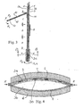
- a row of four mutually spaced spot welds 3c spaced from the bottom edge 4 attach the lower end of the intermediate film 3 to the lower end of the distal film 2 such that the lower end of the intermediate film 3 is forced to follow the lower end of the distal film 2 when the stiffening strips 6 and 7 are flexed away from each other as illustrated in Fig.4 .
- a face plate 8 of a skin friendly adhesive barrier material is attached to film 1.
- the face plate 8 is permanently attached to the film 1.
- the face plate and film 1 may be selectively detachable (not shown), in which case the appliance would be of a so-called two-piece construction.
- the face plate 8 serves to attach the pouch to the peristomal skin surface of a wearer of the ostomy pouch in a manner well known in the art.
- the face plate 8 and the film 1 to which the face plate is attached are provided with aligned stoma-receiving apertures 8a or, alternatively, with aligned starter openings which may be enlarged at the time of application by cutting with scissors, all as well known in the art.
- the apertures 8a allow stoma effluents such as faeces and flatus gas to enter the pouch cavity.
- the intermediate film 3 is provided near the upper end thereof with two pairs of cross cuts defining two openings 8b for allowing flatus gasses to pass from the faeces chamber 3b to the flatus gas chamber 3a.
- the flatus gasses then exit from the flatus gas chamber 3a through a flatus gas venting opening 8c in the distal wall 2.
- the intermediate film 3 prevents or restrains passage of faecal material from chamber 3b to chamber 3a so as not to clog a not shown flatus gas filter arranged so as to cover the a flatus gas venting opening 8c, as shown and described in US patent 5,690,623 .
- interlocking means such as Velcro (hook or loop portion), DUOTEC from G. Binder GmbH & Co., Germany (interlocking mushroom elements) or well known repeatedly releasable adhesive coatings
- a flap 10 of flexible film material may be attached to film 1 by welding or adhering an edge portion 11 of flap 10 to film 2.
- a strip 12 of a corresponding interlocking means such as Velcro (loop or hook portion), DUOTEC or the repeatedly releasable adhesive coating is attached to the flap 10.
- the flap 10 is shown in different positions in Figs. 1, 2 and in Fig. 3 , the position of flap 10 shown in Fig. 3 being rotated in the direction R1 compared to the position of flap 10 shown in Figs.1 and 2 where the flap 10 abuts the film 2, i.e. being rotated as far as possible in the direction R2.
- the flap 10 may include a gripping tab 13 for being gripped by the user's fingers.
- the faeces chamber 3b of the pouch with the discharge aperture 5 closed as described below is gradually filled with faeces while the flatus gasses are vented through the venting openings 8b and the flatus gas opening 8c. It may happen that some liquid faeces enters the flatus gas chamber 3a through the openings 8b, especially if the ostomate is physically active or during the night where pressure can be exerted on the pouch pressing liquid faeces through the openings 8b.
- Figs. 1-4 where the drainage outlet 5 is open.
- the faeces in the faeces chamber 3b are pressed out through the opening 5 and any faeces in the flatus gas chamber 3a are pressed out through the spaces or channels between the spot welds 3c.
- the discharge portion of the pouch is closed in the following manner after the chambers 3a and 3b have been emptied through the drainage outlet 5 as described above:
- the strips 6 and 7 are pressed together to squeeze any remaining matter out from the area between the strips 6 and 7. Then the strips are pulled or flexed apart by applying finger pressure to the ends thereof in the direction of arrows R in Figs. 1 and 2 and 4 so as to be able to access the faeces between the strips 6 and 7 at the drainage outlet 5 for removal thereof.
- the bottom edge portions of the films 1-3 along the drainage outlet 5 are then wiped clean with a cleaning implement, such as, for example, a tissue.
- the bottom end portion of film 3 does not make it difficult to clean the drainage outlet 5 by being loose and thereby interfering with the action of the cleaning implement.
- FIG. 4 where the thickness of the strips 6 and 7 and the films 1-3 is exaggerated for the sake of clarity
- the drainage outlet 5 is maintained open by flexing the strips 6 and 7 apart by finger pressure applied to the ends thereof in the directions represented by the arrows R.
- the interior of the bottom part of the drainage portion is easily accessible for being cleaned, for instance with a cleaning tissue, without interference from the bottom edge portion of the intermediate film 3 as this edge portion is held close to the bottom edge portion of distal film 2 by the spot welds 3c.
- the strips 6 and 7 are rotated clock-wise in the direction of arrow R3 in Fig. 3 until strip 7 abuts the area a of film 2. Thereafter the strips 6 and 7 are rotated 15 once more clock-wise until strip 6 abuts area b of film 2. Finally, the strips 6 and 7 are rotated one last time clock-wise such that the coil formed by the strips 6, 7 and 9 as well as the portions of films 1, 2 and 3 involved abuts the area c of film 2 with the strip 9 of Velcro or the like located such that the corresponding strip 12 of Velcro or the like can engage it by rotating the flap 10 in the direction R1 until the two Velcro strips 9 and 12 abut and engage each other for locking the coil in the final closed and secured position of the discharge portion.
- the upper edge of the coil should preferably fit snugly and tightly in the angle formed between the portion 11 and the rest of the flap 10 such that pressure is exerted thereby on the coil and the portion 11 which is beneficial to the stability of the closure.
- the stiffness of the strips 6 and 7 also is helpful to achieve the stability of the closure.
- the angle or fold between the portion 11 and the rest of the flap 10 furthermore affords the advantage that the flap 10 in its relaxed state will tend to be in an open position not abutting film 2 in which it is easy to grip when rolling the discharge portion up.
- the flap 10 When the pouch is to be drained, the flap 10 is gripped by the tab 13 and pulled such that the strips 9 and 12 are disengaged so that the coil can be unrolled by rotating the strips 6 and 7 three times in the counter clock-wise direction, as oriented in Fig. 3 .
- the strips 6 and 7 may be used to control the rate of drainage of the pouch by opening and closing the drainage outlet 5 by pressing more or less forcefully on the ends of the strips 6 and 7 in the direction of the arrows R so that they flex away from and towards each other, respectively.
- spot welds 3c are shown, more or less the same effect will be achieved with a single centrally located spot weld or two, three or five mutually spaced spot welds.
- the shown four spot welds 3c are currently preferred because it gives the best visual impression.
- the spot welds 3c may be substituted by adhesive spots.
- the two openings 8b in the intermediate film wall may be substituted by a number of small perforations with a size of for instance 0.01mm to 0.5mm.
- the spot welds or adhesive drops may be substituted by a continuous weld or continuous strip of adhesive extending across the entire width of the discharge portion as there then is no need for channels to allow effluent to be emptied out of the flatus gas chamber 3b.
- the bottom edge 4 of the intermediate wall 3 may be located higher than the bottom edges of the films 1 and 2. However, the bottom edge should be in the vicinity of the drainage opening, i.e. not higher than the top edges of the stiffening strips such that the intermediate film is folded at least twice when the strips 6 and 7 are rotated upwards at least 360 degrees, preferably 540 degrees.
- the stiffening strips 6 and 7 are shown overlying each other, the strips may be offset in a direction extending transversely to the longitudinal direction of the drainage portion so that each strip has one end portion extending beyond the corresponding end portion of the other of the offset strips as disclosed in US patent No. 6,887,222 and PCT patent application WO 03/086250 .
Landscapes
- Health & Medical Sciences (AREA)
- Epidemiology (AREA)
- Nursing (AREA)
- Orthopedic Medicine & Surgery (AREA)
- Engineering & Computer Science (AREA)
- Biomedical Technology (AREA)
- Heart & Thoracic Surgery (AREA)
- Vascular Medicine (AREA)
- Life Sciences & Earth Sciences (AREA)
- Animal Behavior & Ethology (AREA)
- General Health & Medical Sciences (AREA)
- Public Health (AREA)
- Veterinary Medicine (AREA)
- Orthopedics, Nursing, And Contraception (AREA)
Claims (11)
- Poche de stomie vidangeable comprenant :- une première ou proximale et une deuxième ou distale parois latérales (1, 2) d'une feuille de matériau flexible scellées l'une à l'autre afin de définir une cavité entre elles destinée à recevoir des écoulements humains de stomie via une ouverture (8a) dans ladite paroi latérale proximale (1) et une portion de vidange allongée s'étendant vers le bas dans une direction longitudinale de ladite poche, ladite portion de vidange se terminant dans une sortie de vidange (5) s'étendant transversalement vers ladite direction longitudinale et formée le long des bords inférieurs desdites première et deuxième parois latérales (1, 2),- une première ou proximale et une seconde ou distale bandes de raidissement flexible (6, 7) situées près de ladite sortie de vidange (5) et s'étendant transversalement vers ladite direction longitudinale et étant fixées aux surfaces externes desdites première et seconde parties latérales (1, 2), respectivement, de ladite portion de vidange,- une troisième paroi intermédiaire (3) en feuille de matériau flexible agencée entre lesdites parois latérales proximale et distale (1, 2) permettant de diviser ladite cavité en deux compartiments, un compartiment proximal pour les excréments (3b) et un compartiment distal pour les gaz de flatulence (3a), et se terminant à un bord inférieur s'étendant transversalement (4) situé à proximité de ladite sortie de vidange (5), et- un moyen de fixation permettant de fixer une bobine comprenant lesdites première et seconde bandes de raidissement (6, 7) et lesdites première, deuxième et troisième parois (1, 2, 3), ladite bobine étant formée en pivotant lesdites bandes (6, 7) vers le haut d'au moins 360 degrés, de préférence d'au moins 540 degrés,caractérisée en ce que
ladite paroi intermédiaire (3) est fixée à une ou plusieurs soudures par point ou un ou plusieurs points d'adhésif à ladite paroi distale (2) à proximité dudit bord inférieur (4) de ladite paroi intermédiaire (3) de sorte que si lesdites bandes de raidissement (6, 7) sont fléchies en position arquée à distance l'une de l'autre afin d'ouvrir ladite sortie de vidange (5), ladite paroi intermédiaire (3) suivra ladite paroi distale (2) et ne gênera pas le nettoyage de ladite sortie de vidange (5) après que ladite poche a été vidée via ladite sortie de vidange (5). - Poche selon la revendication 1, dans laquelle lesdits bords inférieurs (4) desdites première et deuxième parois (1, 2) et de ladite paroi intermédiaire (3) coïncident généralement.
- Poche selon la revendication 1 ou 2, dans laquelle ladite paroi intermédiaire (3) est fixée à ladite paroi distale (2) au moyen d'un soudage.
- Poche selon la revendication 3, dans laquelle ladite soudure est de préférence sous la forme de quatre soudures par point mutuellement espacées de sorte que de préférence deux ou plusieurs canaux permettant de vidanger tout effluent de la stomie dans ledit compartiment pour gaz de flatulence (3a) et permettant l'échappement des gaz de flatulence qui pourraient y être retenus sont formés entre lesdites soudures par point (3c).
- Poche selon l'une quelconque des revendications précédentes, dans laquelle lesdites bandes de raidissement (6, 7) sont généralement rectangulaires.
- Poche selon l'une quelconque des revendications précédentes, dans laquelle lesdites bandes de raidissement (6, 7) se recouvrent généralement l'une l'autre dans une relation généralement parallèle les unes à côté des autres.
- Poche selon l'une quelconque des revendications 5 à 6, dans laquelle les bords inférieurs (4) desdites bandes de raidissement (6, 7) sont situés à une distance de ladite sortie de vidange (5) qui est inférieure à 10 mm, de préférence inférieure à 5 mm et de manière davantage préférée inférieure à 2 mm.
- Poche selon l'une quelconque des revendications précédentes, dans laquelle ladite paroi intermédiaire (3) est fixée à ladite paroi distale (2) à une distance de ladite sortie de vidange (5) qui est inférieure à 15 mm, de préférence inférieure à 10 mm et de manière préférée entre toutes inférieure à 8 mm.
- Poche selon l'une quelconque des revendications précédentes, dans laquelle une ou plusieurs ouvertures d'évacuation des gaz de flatulence (8b, 8c), de préférence une pluralité de telles ouvertures (8b) sont disposées dans ladite paroi intermédiaire (3) et une ouverture d'évacuation des gaz de flatulence (8c) est disposée dans ladite paroi distale (2).
- Poche selon la revendication 9, dans laquelle lesdites ouvertures d'évacuation des gaz de flatulence (8b) dans ladite paroi intermédiaire (3) ont une dimension maximale comprise entre 0,01 mm et 0,5 mm.
- Poche selon la revendication 5, dans laquelle lesdites bandes (6, 7) sont décalées dans des directions s'étendant transversalement vers ladite direction longitudinale de sorte que chaque bande (6, 7) a une portion d'extrémité s'étendant au-delà de la portion d'extrémité correspondante de l'autre des bandes décalées.
Priority Applications (1)
| Application Number | Priority Date | Filing Date | Title |
|---|---|---|---|
| EP08167210A EP2080493B1 (fr) | 2008-01-21 | 2008-10-22 | Poche de stomie vidable à deux chambres |
Applications Claiming Priority (3)
| Application Number | Priority Date | Filing Date | Title |
|---|---|---|---|
| US2247708P | 2008-01-21 | 2008-01-21 | |
| EP08100675 | 2008-01-21 | ||
| EP08167210A EP2080493B1 (fr) | 2008-01-21 | 2008-10-22 | Poche de stomie vidable à deux chambres |
Publications (2)
| Publication Number | Publication Date |
|---|---|
| EP2080493A1 EP2080493A1 (fr) | 2009-07-22 |
| EP2080493B1 true EP2080493B1 (fr) | 2012-03-14 |
Family
ID=39357843
Family Applications (1)
| Application Number | Title | Priority Date | Filing Date |
|---|---|---|---|
| EP08167210A Active EP2080493B1 (fr) | 2008-01-21 | 2008-10-22 | Poche de stomie vidable à deux chambres |
Country Status (2)
| Country | Link |
|---|---|
| EP (1) | EP2080493B1 (fr) |
| AT (1) | ATE548999T1 (fr) |
Families Citing this family (1)
| Publication number | Priority date | Publication date | Assignee | Title |
|---|---|---|---|---|
| CA3156461A1 (fr) * | 2019-10-04 | 2021-04-08 | Convatec Limited | Appareil de stomie |
Family Cites Families (4)
| Publication number | Priority date | Publication date | Assignee | Title |
|---|---|---|---|---|
| US5690623A (en) | 1997-01-13 | 1997-11-25 | Dansac A/S | Vented ostomy pouch with protected gas filter |
| ATE425724T1 (de) | 2002-02-08 | 2009-04-15 | Hollister Inc | Ostomiebeutel mit vorspannungselementen und verschlusmitteln |
| DK174983B1 (da) | 2002-04-10 | 2004-04-05 | Hollister Inc | Tømbar stomipose med integreret lukke |
| GB2413083B (en) * | 2004-04-16 | 2008-04-16 | Salts Healthcare Ltd | Ostomy bag with gas vent and filter |
-
2008
- 2008-10-22 EP EP08167210A patent/EP2080493B1/fr active Active
- 2008-10-22 AT AT08167210T patent/ATE548999T1/de active
Also Published As
| Publication number | Publication date |
|---|---|
| ATE548999T1 (de) | 2012-03-15 |
| EP2080493A1 (fr) | 2009-07-22 |
Similar Documents
| Publication | Publication Date | Title |
|---|---|---|
| EP1496820B1 (fr) | Poche stomique vidable pourvue d'une fermeture | |
| US20240058159A1 (en) | Drainable ostomy pouch | |
| EP3606480B1 (fr) | Orifice de sortie de poche de stomie drainable | |
| EP2827811B1 (fr) | Poche pour stomie drainable | |
| JP7792355B2 (ja) | オストミーパウチ | |
| US20070265588A1 (en) | Drainable ostomy pouch with integrated closure | |
| WO2002102288A1 (fr) | Poche d'ostomie drainable et moyens de fermeture y relatifs | |
| EP2022451B1 (fr) | Poche de stomie vidable disposant de bandes de renforcement avec plusieurs rainures | |
| EP2080493B1 (fr) | Poche de stomie vidable à deux chambres | |
| JP3131250U (ja) | ドレナブル排泄物収容装具 | |
| EP3169284B1 (fr) | Sac collecteur vidangeable | |
| JP2005211178A (ja) | ドレナブル排泄物収容装具 |
Legal Events
| Date | Code | Title | Description |
|---|---|---|---|
| PUAI | Public reference made under article 153(3) epc to a published international application that has entered the european phase |
Free format text: ORIGINAL CODE: 0009012 |
|
| AK | Designated contracting states |
Kind code of ref document: A1 Designated state(s): AT BE BG CH CY CZ DE DK EE ES FI FR GB GR HR HU IE IS IT LI LT LU LV MC MT NL NO PL PT RO SE SI SK TR |
|
| AX | Request for extension of the european patent |
Extension state: AL BA MK RS |
|
| 17P | Request for examination filed |
Effective date: 20100120 |
|
| 17Q | First examination report despatched |
Effective date: 20100218 |
|
| AKX | Designation fees paid |
Designated state(s): AT BE BG CH CY CZ DE DK EE ES FI FR GB GR HR HU IE IS IT LI LT LU LV MC MT NL NO PL PT RO SE SI SK TR |
|
| GRAP | Despatch of communication of intention to grant a patent |
Free format text: ORIGINAL CODE: EPIDOSNIGR1 |
|
| GRAS | Grant fee paid |
Free format text: ORIGINAL CODE: EPIDOSNIGR3 |
|
| GRAA | (expected) grant |
Free format text: ORIGINAL CODE: 0009210 |
|
| AK | Designated contracting states |
Kind code of ref document: B1 Designated state(s): AT BE BG CH CY CZ DE DK EE ES FI FR GB GR HR HU IE IS IT LI LT LU LV MC MT NL NO PL PT RO SE SI SK TR |
|
| REG | Reference to a national code |
Ref country code: GB Ref legal event code: FG4D |
|
| REG | Reference to a national code |
Ref country code: AT Ref legal event code: REF Ref document number: 548999 Country of ref document: AT Kind code of ref document: T Effective date: 20120315 Ref country code: CH Ref legal event code: EP |
|
| REG | Reference to a national code |
Ref country code: IE Ref legal event code: FG4D |
|
| REG | Reference to a national code |
Ref country code: DE Ref legal event code: R096 Ref document number: 602008014072 Country of ref document: DE Effective date: 20120510 |
|
| REG | Reference to a national code |
Ref country code: NL Ref legal event code: VDEP Effective date: 20120314 |
|
| PG25 | Lapsed in a contracting state [announced via postgrant information from national office to epo] |
Ref country code: LT Free format text: LAPSE BECAUSE OF FAILURE TO SUBMIT A TRANSLATION OF THE DESCRIPTION OR TO PAY THE FEE WITHIN THE PRESCRIBED TIME-LIMIT Effective date: 20120314 Ref country code: HR Free format text: LAPSE BECAUSE OF FAILURE TO SUBMIT A TRANSLATION OF THE DESCRIPTION OR TO PAY THE FEE WITHIN THE PRESCRIBED TIME-LIMIT Effective date: 20120314 Ref country code: NO Free format text: LAPSE BECAUSE OF FAILURE TO SUBMIT A TRANSLATION OF THE DESCRIPTION OR TO PAY THE FEE WITHIN THE PRESCRIBED TIME-LIMIT Effective date: 20120614 |
|
| LTIE | Lt: invalidation of european patent or patent extension |
Effective date: 20120314 |
|
| PG25 | Lapsed in a contracting state [announced via postgrant information from national office to epo] |
Ref country code: FI Free format text: LAPSE BECAUSE OF FAILURE TO SUBMIT A TRANSLATION OF THE DESCRIPTION OR TO PAY THE FEE WITHIN THE PRESCRIBED TIME-LIMIT Effective date: 20120314 Ref country code: LV Free format text: LAPSE BECAUSE OF FAILURE TO SUBMIT A TRANSLATION OF THE DESCRIPTION OR TO PAY THE FEE WITHIN THE PRESCRIBED TIME-LIMIT Effective date: 20120314 Ref country code: GR Free format text: LAPSE BECAUSE OF FAILURE TO SUBMIT A TRANSLATION OF THE DESCRIPTION OR TO PAY THE FEE WITHIN THE PRESCRIBED TIME-LIMIT Effective date: 20120615 |
|
| REG | Reference to a national code |
Ref country code: AT Ref legal event code: MK05 Ref document number: 548999 Country of ref document: AT Kind code of ref document: T Effective date: 20120314 |
|
| PG25 | Lapsed in a contracting state [announced via postgrant information from national office to epo] |
Ref country code: CY Free format text: LAPSE BECAUSE OF FAILURE TO SUBMIT A TRANSLATION OF THE DESCRIPTION OR TO PAY THE FEE WITHIN THE PRESCRIBED TIME-LIMIT Effective date: 20120314 |
|
| PG25 | Lapsed in a contracting state [announced via postgrant information from national office to epo] |
Ref country code: PL Free format text: LAPSE BECAUSE OF FAILURE TO SUBMIT A TRANSLATION OF THE DESCRIPTION OR TO PAY THE FEE WITHIN THE PRESCRIBED TIME-LIMIT Effective date: 20120314 Ref country code: EE Free format text: LAPSE BECAUSE OF FAILURE TO SUBMIT A TRANSLATION OF THE DESCRIPTION OR TO PAY THE FEE WITHIN THE PRESCRIBED TIME-LIMIT Effective date: 20120314 Ref country code: IS Free format text: LAPSE BECAUSE OF FAILURE TO SUBMIT A TRANSLATION OF THE DESCRIPTION OR TO PAY THE FEE WITHIN THE PRESCRIBED TIME-LIMIT Effective date: 20120714 Ref country code: RO Free format text: LAPSE BECAUSE OF FAILURE TO SUBMIT A TRANSLATION OF THE DESCRIPTION OR TO PAY THE FEE WITHIN THE PRESCRIBED TIME-LIMIT Effective date: 20120314 Ref country code: SI Free format text: LAPSE BECAUSE OF FAILURE TO SUBMIT A TRANSLATION OF THE DESCRIPTION OR TO PAY THE FEE WITHIN THE PRESCRIBED TIME-LIMIT Effective date: 20120314 Ref country code: CZ Free format text: LAPSE BECAUSE OF FAILURE TO SUBMIT A TRANSLATION OF THE DESCRIPTION OR TO PAY THE FEE WITHIN THE PRESCRIBED TIME-LIMIT Effective date: 20120314 Ref country code: SE Free format text: LAPSE BECAUSE OF FAILURE TO SUBMIT A TRANSLATION OF THE DESCRIPTION OR TO PAY THE FEE WITHIN THE PRESCRIBED TIME-LIMIT Effective date: 20120314 Ref country code: BE Free format text: LAPSE BECAUSE OF FAILURE TO SUBMIT A TRANSLATION OF THE DESCRIPTION OR TO PAY THE FEE WITHIN THE PRESCRIBED TIME-LIMIT Effective date: 20120314 |
|
| PG25 | Lapsed in a contracting state [announced via postgrant information from national office to epo] |
Ref country code: PT Free format text: LAPSE BECAUSE OF FAILURE TO SUBMIT A TRANSLATION OF THE DESCRIPTION OR TO PAY THE FEE WITHIN THE PRESCRIBED TIME-LIMIT Effective date: 20120716 Ref country code: SK Free format text: LAPSE BECAUSE OF FAILURE TO SUBMIT A TRANSLATION OF THE DESCRIPTION OR TO PAY THE FEE WITHIN THE PRESCRIBED TIME-LIMIT Effective date: 20120314 |
|
| PLBE | No opposition filed within time limit |
Free format text: ORIGINAL CODE: 0009261 |
|
| STAA | Information on the status of an ep patent application or granted ep patent |
Free format text: STATUS: NO OPPOSITION FILED WITHIN TIME LIMIT |
|
| PG25 | Lapsed in a contracting state [announced via postgrant information from national office to epo] |
Ref country code: DK Free format text: LAPSE BECAUSE OF FAILURE TO SUBMIT A TRANSLATION OF THE DESCRIPTION OR TO PAY THE FEE WITHIN THE PRESCRIBED TIME-LIMIT Effective date: 20120314 Ref country code: AT Free format text: LAPSE BECAUSE OF FAILURE TO SUBMIT A TRANSLATION OF THE DESCRIPTION OR TO PAY THE FEE WITHIN THE PRESCRIBED TIME-LIMIT Effective date: 20120314 Ref country code: NL Free format text: LAPSE BECAUSE OF FAILURE TO SUBMIT A TRANSLATION OF THE DESCRIPTION OR TO PAY THE FEE WITHIN THE PRESCRIBED TIME-LIMIT Effective date: 20120314 |
|
| 26N | No opposition filed |
Effective date: 20121217 |
|
| PG25 | Lapsed in a contracting state [announced via postgrant information from national office to epo] |
Ref country code: IT Free format text: LAPSE BECAUSE OF FAILURE TO SUBMIT A TRANSLATION OF THE DESCRIPTION OR TO PAY THE FEE WITHIN THE PRESCRIBED TIME-LIMIT Effective date: 20120314 |
|
| REG | Reference to a national code |
Ref country code: DE Ref legal event code: R097 Ref document number: 602008014072 Country of ref document: DE Effective date: 20121217 |
|
| PG25 | Lapsed in a contracting state [announced via postgrant information from national office to epo] |
Ref country code: ES Free format text: LAPSE BECAUSE OF FAILURE TO SUBMIT A TRANSLATION OF THE DESCRIPTION OR TO PAY THE FEE WITHIN THE PRESCRIBED TIME-LIMIT Effective date: 20120625 |
|
| PG25 | Lapsed in a contracting state [announced via postgrant information from national office to epo] |
Ref country code: MC Free format text: LAPSE BECAUSE OF NON-PAYMENT OF DUE FEES Effective date: 20121031 |
|
| REG | Reference to a national code |
Ref country code: CH Ref legal event code: PL |
|
| REG | Reference to a national code |
Ref country code: IE Ref legal event code: MM4A |
|
| REG | Reference to a national code |
Ref country code: FR Ref legal event code: ST Effective date: 20130628 |
|
| PG25 | Lapsed in a contracting state [announced via postgrant information from national office to epo] |
Ref country code: CH Free format text: LAPSE BECAUSE OF NON-PAYMENT OF DUE FEES Effective date: 20121031 Ref country code: BG Free format text: LAPSE BECAUSE OF FAILURE TO SUBMIT A TRANSLATION OF THE DESCRIPTION OR TO PAY THE FEE WITHIN THE PRESCRIBED TIME-LIMIT Effective date: 20120614 Ref country code: IE Free format text: LAPSE BECAUSE OF NON-PAYMENT OF DUE FEES Effective date: 20121022 Ref country code: LI Free format text: LAPSE BECAUSE OF NON-PAYMENT OF DUE FEES Effective date: 20121031 |
|
| PG25 | Lapsed in a contracting state [announced via postgrant information from national office to epo] |
Ref country code: FR Free format text: LAPSE BECAUSE OF NON-PAYMENT OF DUE FEES Effective date: 20121031 |
|
| PG25 | Lapsed in a contracting state [announced via postgrant information from national office to epo] |
Ref country code: MT Free format text: LAPSE BECAUSE OF FAILURE TO SUBMIT A TRANSLATION OF THE DESCRIPTION OR TO PAY THE FEE WITHIN THE PRESCRIBED TIME-LIMIT Effective date: 20120314 |
|
| PG25 | Lapsed in a contracting state [announced via postgrant information from national office to epo] |
Ref country code: TR Free format text: LAPSE BECAUSE OF FAILURE TO SUBMIT A TRANSLATION OF THE DESCRIPTION OR TO PAY THE FEE WITHIN THE PRESCRIBED TIME-LIMIT Effective date: 20120314 |
|
| PG25 | Lapsed in a contracting state [announced via postgrant information from national office to epo] |
Ref country code: LU Free format text: LAPSE BECAUSE OF NON-PAYMENT OF DUE FEES Effective date: 20121022 |
|
| PG25 | Lapsed in a contracting state [announced via postgrant information from national office to epo] |
Ref country code: HU Free format text: LAPSE BECAUSE OF FAILURE TO SUBMIT A TRANSLATION OF THE DESCRIPTION OR TO PAY THE FEE WITHIN THE PRESCRIBED TIME-LIMIT Effective date: 20081022 |
|
| PGFP | Annual fee paid to national office [announced via postgrant information from national office to epo] |
Ref country code: DE Payment date: 20241029 Year of fee payment: 17 |
|
| PGFP | Annual fee paid to national office [announced via postgrant information from national office to epo] |
Ref country code: GB Payment date: 20241028 Year of fee payment: 17 |