EP2080567B1 - Stoppvorrichtung für ein Reinigungselement in einem Rohr zur Verteilung von Beton - Google Patents
Stoppvorrichtung für ein Reinigungselement in einem Rohr zur Verteilung von Beton Download PDFInfo
- Publication number
- EP2080567B1 EP2080567B1 EP09150628A EP09150628A EP2080567B1 EP 2080567 B1 EP2080567 B1 EP 2080567B1 EP 09150628 A EP09150628 A EP 09150628A EP 09150628 A EP09150628 A EP 09150628A EP 2080567 B1 EP2080567 B1 EP 2080567B1
- Authority
- EP
- European Patent Office
- Prior art keywords
- mouth
- stopper
- distribution pipe
- stop device
- pipe
- Prior art date
- Legal status (The legal status is an assumption and is not a legal conclusion. Google has not performed a legal analysis and makes no representation as to the accuracy of the status listed.)
- Not-in-force
Links
Images


Classifications
-
- B—PERFORMING OPERATIONS; TRANSPORTING
- B08—CLEANING
- B08B—CLEANING IN GENERAL; PREVENTION OF FOULING IN GENERAL
- B08B9/00—Cleaning hollow articles by methods or apparatus specially adapted thereto
- B08B9/02—Cleaning pipes or tubes or systems of pipes or tubes
- B08B9/027—Cleaning the internal surfaces; Removal of blockages
- B08B9/04—Cleaning the internal surfaces; Removal of blockages using cleaning devices introduced into and moved along the pipes
- B08B9/053—Cleaning the internal surfaces; Removal of blockages using cleaning devices introduced into and moved along the pipes moved along the pipes by a fluid, e.g. by fluid pressure or by suction
- B08B9/055—Cleaning the internal surfaces; Removal of blockages using cleaning devices introduced into and moved along the pipes moved along the pipes by a fluid, e.g. by fluid pressure or by suction the cleaning devices conforming to, or being conformable to, substantially the same cross-section of the pipes, e.g. pigs or moles
-
- F—MECHANICAL ENGINEERING; LIGHTING; HEATING; WEAPONS; BLASTING
- F16—ENGINEERING ELEMENTS AND UNITS; GENERAL MEASURES FOR PRODUCING AND MAINTAINING EFFECTIVE FUNCTIONING OF MACHINES OR INSTALLATIONS; THERMAL INSULATION IN GENERAL
- F16L—PIPES; JOINTS OR FITTINGS FOR PIPES; SUPPORTS FOR PIPES, CABLES OR PROTECTIVE TUBING; MEANS FOR THERMAL INSULATION IN GENERAL
- F16L55/00—Devices or appurtenances for use in, or in connection with, pipes or pipe systems
- F16L55/26—Pigs or moles, i.e. devices movable in a pipe or conduit with or without self-contained propulsion means
- F16L55/46—Launching or retrieval of pigs or moles
Definitions
- the present invention concerns a stop device for a cleaning element in a pipe for the distribution of concrete or other material similar to concrete, used on heavy work vehicles, such as for example a truck or concrete mixer.
- the stop device is applied to a mouth of a concrete distribution pipe for the selective insertion, into the cavity of the pipe, of an element suitable to stop the advance of a cleaning element, normally called a ball, introduced at one end of the distribution pipe, shot at high pressure or sucked in, in order to remove residual concrete from the walls of the distribution pipe.
- a cleaning element normally called a ball
- the stop element is disposed in a first position, where it does not impede the advance of the concrete inside the distribution pipe.
- the stop element is disposed in the corresponding stopper in a second position, inside the distribution pipe, so as to at least partly occupy the seating where the ball advances inside the pipe.
- stop element One disadvantage of the known stop element is that, during the delivery of the concrete, the stresses on the wall of the distribution pipe in correspondence with the mouth, closed at the surface by the stopper, are very high and contribute to the premature wear of the portion of distribution pipe associated with the mouth, and may even cause it to break due to stress. This is because the free volume between the stopper and the cavity of the pipe, when the concrete is sucked in, causes localized vortexes and depressions with consequent stresses concentrated on the section of the pipe adj acent to the zone where the stopper is inserted.
- Rods are provided to be selectively inserted into the cylindrical housing through specific openings made in the same cylindrical housing, in order to act as stop means for the scraper.
- This known scraper has a complex constructional design at least because of the provision of the hole for removing the scraper and also of the openings for the rods.
- a further disadvantage of this type of scraper is that the provision of surfaces with discontinuity defined by the hole for the scraper and the openings and also the changes in the slope of the cross-section connecting the housing of the scraper and the scrapeable pipeline, where some openings for the rods are made, determine, also in this case, vortexes and depressions, with consequent stresses in the zone adjacent the stop means.
- particles and coarse crushed aggregate which are typical in concrete, hit said surfaces with discontinuity of the cylindrical housing and the pipeline, thus causing the premature wear thereof and the formation of holes.
- US-A-6,029,302 discloses the features of the preamble of claim 1.
- Purpose of the present invention is therefore to achieve a stop device for a cleaning element in a pipe for the distribution of concrete, or material similar to concrete, which allows to increase the operating duration of the distribution pipe and to prevent localized stresses on the wall of the pipe.
- the Applicant has devised, tested and embodied the present invention to overcome the shortcomings of the state of the art and to obtain these and other purposes and advantages.
- a stop device for a cleaning element in a pipe for the distribution of concrete, or material similar to concrete, according to the present invention is suitable to be coupled with a mouth of the distribution pipe, or a portion thereof, through which a cleaning element or ball is removed, used to clean the inner wall of the pipe from residues or incrustations of concrete.
- the stop device comprises a stopper suitable to be coupled, with a lower portion thereof, in a position to close said mouth both during the distribution of the concrete and also during the cleaning of the distribution pipe.
- the stop device also comprises a stop element, elongated in shape, able to be inserted in a hole of the stopper, and to slide between a first position, at least partly outside the pipe and assumed during the distribution of the concrete, and a second position, inside the pipe and substantially transverse to the direction of advance of the ball, during the cleaning of the pipe.
- a stop element elongated in shape, able to be inserted in a hole of the stopper, and to slide between a first position, at least partly outside the pipe and assumed during the distribution of the concrete, and a second position, inside the pipe and substantially transverse to the direction of advance of the ball, during the cleaning of the pipe.
- the lower portion of the stopper is associated with an internal cavity of the mouth and comprises a body able to fill, during use, substantially the whole volume defined inside by the mouth.
- the surface of said lower portion, disposed during use toward the inside of the distribution pipe is shaped so as to define, in correspondence with the portion of distribution pipe comprising the mouth, together with the internal surface of the wall of the distribution pipe, a continuous profile indistinguishable from the internal profile of the distribution pipe in correspondence with transverse sections of the distribution pipe, before and after said portion of the distribution pipe.
- the stopper comprises attachment elements suitable to cooperate with associated clamping elements disposed on the distribution pipe in order to clamp the stopper in a position to close the access mouth to the pipe.
- the attachment elements comprise anti-unscrewing means.
- the attachment elements are made in a single piece with the stopper of the stop device.
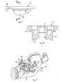
- a stop device 13 for a cleaning element for a pipe 10 for the distribution of concrete or other material similar to concrete, according to the present invention is coupled with a lateral mouth 20 of the distribution pipe 10.
- the distribution pipe 10 comprises a plurality of segments 11 joined by joints of a known type and constrained by attachment elements 12 to an arm for the distribution of the concrete, for example extendible, mounted on a work vehicle of a known type and not shown in the drawings. At least a first segment 11 of said distribution pipe 10 is connected directly to the work vehicle.
- the lateral mouth 20 of the distribution pipe 10, with a substantially circular section, is used for the removal of a cleaning element, or ball, shot at high pressure or sucked in at one end of the distribution pipe 10, so as to clean the internal walls of the distribution pipe 10 of residues and incrustations by means of scraping, at the end of the delivery of concrete.
- the stop device 13 comprises a stopper 14 suitable to be coupled, with a lower portion thereof, in a position to close said mouth 20, both during the distribution of the concrete and also during the cleaning of the distribution pipe 10.
- the stopper 14 comprises a circular lower portion provided with a circular step 24 resting on the lateral mouth 20 and a cylindrical lateral surface 23 ( figs. 5 and 6 ) coupled with the internal cylindrical surface of the mouth 20.
- the stopper 14 also comprises a hole 15 able to define, together with a hollow seating 16, a through seating for a stop element 17, also denominated hereafter as a stop, and suitable to clamp the ball during the cleaning of the internal wall of the distribution pipe 10.
- the stop 17 is able to slide axially through said through seating between a first position, at least partly outside the distribution pipe 10, and a second position inside the distribution pipe 10 and transverse to the direction of advance both of the ball and also of the concrete, so as to stop the advance of the ball during said cleaning.
- One end 18 of the stop 17 is housed in the hollow seating 16 when the stop 17 is disposed in its first position.
- the lower portion of the stopper 14 associated with the internal cavity of the mouth comprises a body suitable to fill, during use, the whole volume defined by said cavity. Furthermore, a lower surface 22 ( figs. 2 , 5 and 6 ) of said lower portion of the stopper 14, disposed during use toward the inside of the distribution pipe 10, is shaped so as to define a continuous profile, together with the shaping of the internal surface 26 of the wall of the distribution pipe 10. The continuous profile is such as to be indistinguishable from the internal profile of the distribution pipe 10 in correspondence with its transverse sections, before or after the mouth 20.
- the lower surface 22 of the stopper 14, disposed to close the mouth 20, and the internal surface 26 of the distribution pipe 10 in correspondence with the mouth 20, achieve a single internal profile whose transverse sections, defined by the intersection of planes orthogonal to said direction of advance, are substantially circular and continuous with the cross sections of the distribution pipe 10 before or after the portion comprising the mouth 20.
- the stopper 14 also comprises two attachment wings 30 with a square or rectangular shape ( fig. 4 ), diametrically opposite and protruding with respect to the body of the stopper 14, and suitable to be coupled with an equal number of cylindrical pins 44, disposed on the external surface of the distribution pipe 10 in order to clamp the stopper 14 in said closing position.
- the attachment wings 30 are made in a single piece with the body of the stopper 14.
- each attachment wing 30 cooperates with the pins 44 during a rotation of the stopper 14 in order to dispose it in said position to close the mouth 20.
- Each attachment wing 30 comprises anti-unscrewing means.
- each attachment wing 30 comprises a hollow seating 32 open on one side of the wing 30 and suitable to cooperate with the associated pin 44.
- the hollow seating 32 comprises an elongated U-shaped profile, rounded at one end suitable for coupling with the lateral surface of the pin 44, and substantially parallel to the external profile of the stopper 14.
- the transverse size of the hollow seating 32 is at least equal to the transverse thickness of said pins 44.
- Each attachment wing 30 also comprises a circular seating 34, substantially concentric to the terminal portion of said hollow seating 32, and such as to define, together with the corresponding hollow seating 32, a semi-circular step for the insertion of a corresponding holed end of a clamping handle 40 and suitable to clamp the stopper 14 in the closed position of the mouth 20.
- the clamping handle 40 is therefore coupled both with the pin 44 and also with the hollow seating 32 in order to prevent the rotation of the stopper 14 from its position where it closes the mouth 20.
- the stop device 13 as described heretofore functions as follows.
- the mouth 20 is closed by the stopper 14 in its closing position and with the stop 17 disposed in its first position.
- the stop 17 is disposed in its second position, so as to occupy transversely the seating where the concrete advances, and therefore the ball, and obstruct the advance of the ball in correspondence with the mouth 20.
- the ball is shot or sucked into the distribution pipe 10, for example by inverting the direction of functioning of the delivery pump, allowing to clean the walls due to the surface scraping of the ball in contact with the internal wall of the pipe 10.
- the stopper 14 is removed from the mouth 20 so as to allow access inside the pipe 10 and the subsequent removal of the ball stopped by the stop 17.
- each clamping handle 40 is removed from the associated pin 44 and then from the circular seating 34 of the attachment wing 30.
- the stopper 14 is rotated so as to disengage each pin 44 from the corresponding hollow seating 32 of the attachment wing 30.
- the stopper 14 is raised and removed from the mouth 20 and the ball is removed through the mouth 20.
- the stopper 14 is again positioned in its position to close the mouth 20, performing in inverse sequence the removal operations just described.
- stop device 13 for a cleaning element in a pipe for the distribution of concrete, having the characteristics as set forth in the claims and hence all coming within the field of protection defined thereby.
Landscapes
- Engineering & Computer Science (AREA)
- General Engineering & Computer Science (AREA)
- Mechanical Engineering (AREA)
- Chemical & Material Sciences (AREA)
- Combustion & Propulsion (AREA)
- Physics & Mathematics (AREA)
- Fluid Mechanics (AREA)
- Cleaning In General (AREA)
- Forms Removed On Construction Sites Or Auxiliary Members Thereof (AREA)
- Sink And Installation For Waste Water (AREA)
Claims (11)
- Anschlagvorrichtung für ein kugelartiges Reinigungselement in einem Rohr (10) zum Verteilen von Beton oder einem anderen ähnlichen Material, Folgendes umfassend:- einen Stopper (14), der mit einer seitlichen Öffnung (20) des Rohrs (10) verbunden werden kann und einen unteren Abschnitt hat, um die Öffnung (20) des Verteilerrohrs (10) in einer Betriebsstellung von diesem zu schließen,- ein Anschlagelement (17), das von der Form her langgestreckt ist und in ein Loch (15) des Stoppers (14) eingesteckt werden kann und zwischen einer ersten Position zumindest teilweise außerhalb des Verteilerrohrs (10) und einer zweiten Position innerhalb des Verteilerrohrs (10) und quer zur Vorrückrichtung des kugelartigen Reinigungselements gleiten kann, um es zu stoppen, wobei
der untere Abschnitt des Stoppers (14) während des Gebrauchs mit einem Innenhohlraum der Öffnung (20) verbunden ist und einen Körper umfasst, der im Wesentlichen das ganze im Inneren der Öffnung (20) gebildete Volumen einnehmen kann, dadurch gekennzeichnet, dass der untere Abschnitt des Stoppers (14) eine Unterseite (22) umfasst, die während des Gebrauchs zum Inneren des Verteilerrohrs (10) hin angeordnet und bogenförmig ist, um in Übereinstimmung mit einem die Öffnung (20) umfassenden Segment des Verteilerrohrs (10) zusammen mit der Innenfläche (26) der Wand des Verteilerrohrs ein durchgehendes einziges Innenprofil zu bilden, das sich vom Innenprofil des Verteilerrohrs (10) nicht unterscheiden lässt und Querschnitte hat, die Im Wesentlichen kreisrund und durchgehend mit Querschnitten des Verteilerrohrs (10) vor und nach dem die Öffnung (20) umfassenden Segment des Verteilerrohrs (10) sind, und
die seitliche Öffnung (20) des Rohrs (10) dazu ausgelegt ist, die Entnahme des kugelartigen Reinigungselements durch sie hindurch zuzulassen, nachdem das kugelartige Reinigungselement im Inneren des Rohrs (10) gestoppt wurde. - Anschlagvorrichtung nach Anspruch 1, dadurch gekennzeichnet, dass der Stopper (14) aus der Öffnung (20) entnommen werden kann, um die Entnahme des kugelartigen Reinigungselements zuzulassen.
- Anschlagvorrichtung nach einem der vorhergehenden Ansprüche, dadurch gekennzeichnet, dass das Loch (15) einen Hohlsitz (16) umfasst, der ein Ende (18) des in der ersten Position angeordneten Anschlagelements (17) aufnehmen kann.
- Anschlagvorrichtung nach einem der vorhergehenden Ansprüche, dadurch gekennzeichnet, dass der Stopper (14) Befestigungselemente (30) umfasst, die mit dazugehörigen Klemmelementen (44) des Verteilerrohrs (10) verbunden werden können, um den Stopper (14) in der Betriebsposition zum Schließen der Öffnung (20) festzuklemmen.
- Anschlagvorrichtung nach Anspruch 4, dadurch gekennzeichnet, dass die Befestigungselemente (30) ein Lösen der Schraubverbindung verhindernde Einrichtungen umfassen.
- Anschlagvorrichtung nach Anspruch 4 oder 5, dadurch gekennzeichnet, dass die Befestigungselemente (30) des Stoppers (14) einstückig hergestellt sind.
- Anschlagvorrichtung nach einem der Ansprüche 4 bis 6, dadurch gekennzeichnet, dass die Klemmelemente Stifte (44) umfassen.
- Anschlagvorrichtung nach Anspruch 7, dadurch gekennzeichnet, dass die ein Lösen der Schraubverbindung verhindernden Einrichtungen der Befestigungselemente (30) einen offenen Hohlsitz (32) umfassen, der in der Schließposition mit einem zugeordneten Stift (44) zusammenwirken kann und ein U-förmiges Profil und eine Quergröße hat, die zumindest gleich der Querdicke des Stifts (44) ist.
- Anschlagvorrichtung nach Anspruch 8, dadurch gekennzeichnet, dass die ein Lösen der Schraubverbindung verhindernden Einrichtungen der Befestigungselemente (30) auch einen kreisförmigen Sitz (34) umfassen, der zu einem Ende des Hohlsitzes (32) konzentrisch ist, um zusammen mit dem Hohlsitz (32) eine halbkreisförmige Stufe zu bilden, die ein Ende eines Klemmgriffs (40) aufnehmen kann.
- Anschlagvorrichtung nach Anspruch 9, dadurch gekennzeichnet, dass das Ende des Klemmgriffs (40) ein Loch umfasst, das während des Gebrauchs mit dem kreisförmigen Sitz (34) verbunden werden kann, wobei sich einer der Stifte (44) für die ein Lösen der Schraubverbindung verhindernde Klemmbefestigung des Stoppers (14) in der Schließposition befindet,
- Anschlagvorrichtung nach einem der vorhergehenden Ansprüche, dadurch gekennzeichnet, dass die Öffnung (20) einen im Wesentlichen kreisrunden Querschnitt zur Entnahme des kugelartigen Reinigungselements hat, und der untere Abschnitt des Stoppers (14) mit einer kreisförmigen Stufe (24), die auf der Öffnung (20) aufliegt, und einer zylindrischen Seitenfläche (23) versehen ist, die mit der zylindrischen Innenfläche der Öffnung (20) verbunden ist.
Priority Applications (1)
| Application Number | Priority Date | Filing Date | Title |
|---|---|---|---|
| PL09150628T PL2080567T3 (pl) | 2008-01-18 | 2009-01-15 | Układ wstrzymujący dla elementu czyszczącego w rurze do dystrybucji betonu |
Applications Claiming Priority (1)
| Application Number | Priority Date | Filing Date | Title |
|---|---|---|---|
| IT000010A ITUD20080010A1 (it) | 2008-01-18 | 2008-01-18 | Dispositivo di arresto per un elemento pulitore di un tubo di distribuzione di calcestruzzo |
Publications (3)
| Publication Number | Publication Date |
|---|---|
| EP2080567A2 EP2080567A2 (de) | 2009-07-22 |
| EP2080567A3 EP2080567A3 (de) | 2010-05-05 |
| EP2080567B1 true EP2080567B1 (de) | 2011-10-19 |
Family
ID=40290454
Family Applications (1)
| Application Number | Title | Priority Date | Filing Date |
|---|---|---|---|
| EP09150628A Not-in-force EP2080567B1 (de) | 2008-01-18 | 2009-01-15 | Stoppvorrichtung für ein Reinigungselement in einem Rohr zur Verteilung von Beton |
Country Status (6)
| Country | Link |
|---|---|
| EP (1) | EP2080567B1 (de) |
| AT (1) | ATE529199T1 (de) |
| DK (1) | DK2080567T3 (de) |
| ES (1) | ES2375432T3 (de) |
| IT (1) | ITUD20080010A1 (de) |
| PL (1) | PL2080567T3 (de) |
Families Citing this family (3)
| Publication number | Priority date | Publication date | Assignee | Title |
|---|---|---|---|---|
| CN109184218B (zh) * | 2018-09-20 | 2023-08-08 | 中联重科股份有限公司 | 混凝土泵送装置及混凝土泵送设备 |
| CN112337906B (zh) * | 2020-10-16 | 2022-02-18 | 威海玉全新型建筑材料股份有限公司 | 具有除尘功能的混凝土搅拌站及其除尘方法 |
| CN112792999A (zh) * | 2021-01-11 | 2021-05-14 | 崔志明 | 一种环保型加气混凝土制造生产用养护设备 |
Family Cites Families (5)
| Publication number | Priority date | Publication date | Assignee | Title |
|---|---|---|---|---|
| DE3244380A1 (de) * | 1981-12-10 | 1983-06-16 | Herberts Gmbh, 5600 Wuppertal | Ventil fuer molchbare rohrleitungen |
| DE3229103C1 (de) * | 1982-08-04 | 1984-03-01 | WIBAU AG, 6466 Gründau | Reinigungsvorrichtung zur Entleerungsreinigung der Förderleitung einer mit einem Aufgabebehälter ausgerüsteten Betonpumpe |
| US6029302A (en) * | 1995-05-12 | 2000-02-29 | Tuchenhagen Gmbh | Cleanable scraper station |
| JP4235461B2 (ja) * | 2003-02-06 | 2009-03-11 | 阪南鉄工株式会社 | ピグ停止装置 |
| DE102005054336A1 (de) * | 2005-11-11 | 2007-05-16 | Schwing Gmbh F | Betonfördervorrichtung mit Eintragarmatur zum Eintragen eines Reinigungskörpers |
-
2008
- 2008-01-18 IT IT000010A patent/ITUD20080010A1/it unknown
-
2009
- 2009-01-15 DK DK09150628.7T patent/DK2080567T3/da active
- 2009-01-15 ES ES09150628T patent/ES2375432T3/es active Active
- 2009-01-15 AT AT09150628T patent/ATE529199T1/de active
- 2009-01-15 EP EP09150628A patent/EP2080567B1/de not_active Not-in-force
- 2009-01-15 PL PL09150628T patent/PL2080567T3/pl unknown
Also Published As
| Publication number | Publication date |
|---|---|
| ITUD20080010A1 (it) | 2009-07-19 |
| ATE529199T1 (de) | 2011-11-15 |
| EP2080567A3 (de) | 2010-05-05 |
| EP2080567A2 (de) | 2009-07-22 |
| DK2080567T3 (da) | 2012-02-06 |
| ES2375432T3 (es) | 2012-02-29 |
| PL2080567T3 (pl) | 2012-03-30 |
Similar Documents
| Publication | Publication Date | Title |
|---|---|---|
| US9631349B2 (en) | Plunger with toilet declogger | |
| US9707936B2 (en) | Wiper system for spraying a cleaning and/or deicing fluid from the region of a windscreen wiper | |
| CN205047233U (zh) | 一种混凝土喷浆车的喷射装置及混凝土喷浆车 | |
| CA2610544A1 (en) | Connector for filling concrete formworks | |
| EP2080567A2 (de) | Stoppvorrichtung für ein Reinigungselement in einem Rohr zur Verteilung von Beton | |
| EP2372330A1 (de) | Luftblasensensor | |
| KR20130011697A (ko) | 하수관 청소장치 | |
| KR101474298B1 (ko) | 비굴착식 상하수도 보수 시스템 및 공법 | |
| CN101329001A (zh) | 流体管连接装置内齿卡环 | |
| CN101166863B (zh) | 在运输过程中使用的紧固系统 | |
| JP3749140B2 (ja) | 壁面補修方法とその壁面補修用ガン | |
| KR20140146335A (ko) | 볼형 샤프트를 구비한 굴절형 절삭 공구를 가진 관내 고형 물질 제거 장치 | |
| CN211257856U (zh) | 一种混凝土输送管挡料阀门 | |
| DE102017223518A1 (de) | Wischblattvorrichtung | |
| CN207770413U (zh) | 一种自动前行式管道冲洗喷头装置 | |
| WO2020147994A1 (de) | Wischblattvorrichtung | |
| CN204420172U (zh) | 除污型焊接球阀 | |
| DE4039663C2 (de) | ||
| US1720049A (en) | Paraffin scraper | |
| CN121654812B (zh) | 一种湿式喷浆机管道连接接头装置 | |
| CN207405490U (zh) | 一种用于桥梁预应力的孔道压浆的连接设备 | |
| JP4885531B2 (ja) | 観察治具と鋼管内の塗装方法 | |
| CN223000521U (zh) | 一种快速拆卸装置 | |
| KR200237601Y1 (ko) | 콘크리트 균열 보수를 위한 패커 | |
| DE10056253A1 (de) | Reinigungsvorrichtung für Getränkeleitungen |
Legal Events
| Date | Code | Title | Description |
|---|---|---|---|
| PUAI | Public reference made under article 153(3) epc to a published international application that has entered the european phase |
Free format text: ORIGINAL CODE: 0009012 |
|
| AK | Designated contracting states |
Kind code of ref document: A2 Designated state(s): AT BE BG CH CY CZ DE DK EE ES FI FR GB GR HR HU IE IS IT LI LT LU LV MC MK MT NL NO PL PT RO SE SI SK TR |
|
| AX | Request for extension of the european patent |
Extension state: AL BA RS |
|
| PUAL | Search report despatched |
Free format text: ORIGINAL CODE: 0009013 |
|
| AK | Designated contracting states |
Kind code of ref document: A3 Designated state(s): AT BE BG CH CY CZ DE DK EE ES FI FR GB GR HR HU IE IS IT LI LT LU LV MC MK MT NL NO PL PT RO SE SI SK TR |
|
| AX | Request for extension of the european patent |
Extension state: AL BA RS |
|
| 17P | Request for examination filed |
Effective date: 20101104 |
|
| AKX | Designation fees paid |
Designated state(s): AT BE BG CH CY CZ DE DK EE ES FI FR GB GR HR HU IE IS IT LI LT LU LV MC MK MT NL NO PL PT RO SE SI SK TR |
|
| GRAP | Despatch of communication of intention to grant a patent |
Free format text: ORIGINAL CODE: EPIDOSNIGR1 |
|
| RIC1 | Information provided on ipc code assigned before grant |
Ipc: F16L 55/46 20060101ALI20110325BHEP Ipc: B08B 9/055 20060101AFI20110325BHEP |
|
| GRAS | Grant fee paid |
Free format text: ORIGINAL CODE: EPIDOSNIGR3 |
|
| GRAA | (expected) grant |
Free format text: ORIGINAL CODE: 0009210 |
|
| RIN1 | Information on inventor provided before grant (corrected) |
Inventor name: MOSCA, RAFFAELE Inventor name: FERRE, FABIO Inventor name: PIRRI, NICOLA |
|
| AK | Designated contracting states |
Kind code of ref document: B1 Designated state(s): AT BE BG CH CY CZ DE DK EE ES FI FR GB GR HR HU IE IS IT LI LT LU LV MC MK MT NL NO PL PT RO SE SI SK TR |
|
| REG | Reference to a national code |
Ref country code: GB Ref legal event code: FG4D |
|
| REG | Reference to a national code |
Ref country code: CH Ref legal event code: EP |
|
| REG | Reference to a national code |
Ref country code: IE Ref legal event code: FG4D |
|
| REG | Reference to a national code |
Ref country code: CH Ref legal event code: NV Representative=s name: MICHELI & CIE SA |
|
| REG | Reference to a national code |
Ref country code: DE Ref legal event code: R096 Ref document number: 602009003127 Country of ref document: DE Effective date: 20120119 |
|
| REG | Reference to a national code |
Ref country code: NL Ref legal event code: T3 |
|
| REG | Reference to a national code |
Ref country code: DK Ref legal event code: T3 |
|
| REG | Reference to a national code |
Ref country code: SE Ref legal event code: TRGR |
|
| REG | Reference to a national code |
Ref country code: ES Ref legal event code: FG2A Ref document number: 2375432 Country of ref document: ES Kind code of ref document: T3 Effective date: 20120229 |
|
| LTIE | Lt: invalidation of european patent or patent extension |
Effective date: 20111019 |
|
| REG | Reference to a national code |
Ref country code: PL Ref legal event code: T3 |
|
| REG | Reference to a national code |
Ref country code: GR Ref legal event code: EP Ref document number: 20120400119 Country of ref document: GR Effective date: 20120305 |
|
| PG25 | Lapsed in a contracting state [announced via postgrant information from national office to epo] |
Ref country code: IS Free format text: LAPSE BECAUSE OF FAILURE TO SUBMIT A TRANSLATION OF THE DESCRIPTION OR TO PAY THE FEE WITHIN THE PRESCRIBED TIME-LIMIT Effective date: 20120219 Ref country code: LT Free format text: LAPSE BECAUSE OF FAILURE TO SUBMIT A TRANSLATION OF THE DESCRIPTION OR TO PAY THE FEE WITHIN THE PRESCRIBED TIME-LIMIT Effective date: 20111019 Ref country code: NO Free format text: LAPSE BECAUSE OF FAILURE TO SUBMIT A TRANSLATION OF THE DESCRIPTION OR TO PAY THE FEE WITHIN THE PRESCRIBED TIME-LIMIT Effective date: 20120119 |
|
| PG25 | Lapsed in a contracting state [announced via postgrant information from national office to epo] |
Ref country code: LV Free format text: LAPSE BECAUSE OF FAILURE TO SUBMIT A TRANSLATION OF THE DESCRIPTION OR TO PAY THE FEE WITHIN THE PRESCRIBED TIME-LIMIT Effective date: 20111019 Ref country code: SI Free format text: LAPSE BECAUSE OF FAILURE TO SUBMIT A TRANSLATION OF THE DESCRIPTION OR TO PAY THE FEE WITHIN THE PRESCRIBED TIME-LIMIT Effective date: 20111019 Ref country code: HR Free format text: LAPSE BECAUSE OF FAILURE TO SUBMIT A TRANSLATION OF THE DESCRIPTION OR TO PAY THE FEE WITHIN THE PRESCRIBED TIME-LIMIT Effective date: 20111019 Ref country code: PT Free format text: LAPSE BECAUSE OF FAILURE TO SUBMIT A TRANSLATION OF THE DESCRIPTION OR TO PAY THE FEE WITHIN THE PRESCRIBED TIME-LIMIT Effective date: 20120220 |
|
| PG25 | Lapsed in a contracting state [announced via postgrant information from national office to epo] |
Ref country code: CY Free format text: LAPSE BECAUSE OF FAILURE TO SUBMIT A TRANSLATION OF THE DESCRIPTION OR TO PAY THE FEE WITHIN THE PRESCRIBED TIME-LIMIT Effective date: 20111019 |
|
| PG25 | Lapsed in a contracting state [announced via postgrant information from national office to epo] |
Ref country code: EE Free format text: LAPSE BECAUSE OF FAILURE TO SUBMIT A TRANSLATION OF THE DESCRIPTION OR TO PAY THE FEE WITHIN THE PRESCRIBED TIME-LIMIT Effective date: 20111019 Ref country code: SK Free format text: LAPSE BECAUSE OF FAILURE TO SUBMIT A TRANSLATION OF THE DESCRIPTION OR TO PAY THE FEE WITHIN THE PRESCRIBED TIME-LIMIT Effective date: 20111019 Ref country code: CZ Free format text: LAPSE BECAUSE OF FAILURE TO SUBMIT A TRANSLATION OF THE DESCRIPTION OR TO PAY THE FEE WITHIN THE PRESCRIBED TIME-LIMIT Effective date: 20111019 Ref country code: BG Free format text: LAPSE BECAUSE OF FAILURE TO SUBMIT A TRANSLATION OF THE DESCRIPTION OR TO PAY THE FEE WITHIN THE PRESCRIBED TIME-LIMIT Effective date: 20120119 |
|
| PLBE | No opposition filed within time limit |
Free format text: ORIGINAL CODE: 0009261 |
|
| STAA | Information on the status of an ep patent application or granted ep patent |
Free format text: STATUS: NO OPPOSITION FILED WITHIN TIME LIMIT |
|
| PG25 | Lapsed in a contracting state [announced via postgrant information from national office to epo] |
Ref country code: RO Free format text: LAPSE BECAUSE OF FAILURE TO SUBMIT A TRANSLATION OF THE DESCRIPTION OR TO PAY THE FEE WITHIN THE PRESCRIBED TIME-LIMIT Effective date: 20111019 Ref country code: MC Free format text: LAPSE BECAUSE OF NON-PAYMENT OF DUE FEES Effective date: 20120131 |
|
| 26N | No opposition filed |
Effective date: 20120720 |
|
| REG | Reference to a national code |
Ref country code: IE Ref legal event code: MM4A |
|
| REG | Reference to a national code |
Ref country code: DE Ref legal event code: R097 Ref document number: 602009003127 Country of ref document: DE Effective date: 20120720 |
|
| PG25 | Lapsed in a contracting state [announced via postgrant information from national office to epo] |
Ref country code: IE Free format text: LAPSE BECAUSE OF NON-PAYMENT OF DUE FEES Effective date: 20120115 |
|
| PG25 | Lapsed in a contracting state [announced via postgrant information from national office to epo] |
Ref country code: MK Free format text: LAPSE BECAUSE OF FAILURE TO SUBMIT A TRANSLATION OF THE DESCRIPTION OR TO PAY THE FEE WITHIN THE PRESCRIBED TIME-LIMIT Effective date: 20111019 |
|
| PGFP | Annual fee paid to national office [announced via postgrant information from national office to epo] |
Ref country code: GB Payment date: 20130122 Year of fee payment: 5 Ref country code: FI Payment date: 20130111 Year of fee payment: 5 Ref country code: SE Payment date: 20130122 Year of fee payment: 5 Ref country code: DK Payment date: 20130121 Year of fee payment: 5 |
|
| PGFP | Annual fee paid to national office [announced via postgrant information from national office to epo] |
Ref country code: PL Payment date: 20130111 Year of fee payment: 5 Ref country code: GR Payment date: 20130117 Year of fee payment: 5 |
|
| PG25 | Lapsed in a contracting state [announced via postgrant information from national office to epo] |
Ref country code: MT Free format text: LAPSE BECAUSE OF FAILURE TO SUBMIT A TRANSLATION OF THE DESCRIPTION OR TO PAY THE FEE WITHIN THE PRESCRIBED TIME-LIMIT Effective date: 20111019 |
|
| PG25 | Lapsed in a contracting state [announced via postgrant information from national office to epo] |
Ref country code: LU Free format text: LAPSE BECAUSE OF NON-PAYMENT OF DUE FEES Effective date: 20120115 |
|
| PG25 | Lapsed in a contracting state [announced via postgrant information from national office to epo] |
Ref country code: HU Free format text: LAPSE BECAUSE OF FAILURE TO SUBMIT A TRANSLATION OF THE DESCRIPTION OR TO PAY THE FEE WITHIN THE PRESCRIBED TIME-LIMIT Effective date: 20090115 |
|
| REG | Reference to a national code |
Ref country code: DK Ref legal event code: EBP Effective date: 20140131 |
|
| REG | Reference to a national code |
Ref country code: SE Ref legal event code: EUG |
|
| GBPC | Gb: european patent ceased through non-payment of renewal fee |
Effective date: 20140115 |
|
| REG | Reference to a national code |
Ref country code: GR Ref legal event code: ML Ref document number: 20120400119 Country of ref document: GR Effective date: 20140801 |
|
| PG25 | Lapsed in a contracting state [announced via postgrant information from national office to epo] |
Ref country code: GR Free format text: LAPSE BECAUSE OF NON-PAYMENT OF DUE FEES Effective date: 20140801 Ref country code: FI Free format text: LAPSE BECAUSE OF NON-PAYMENT OF DUE FEES Effective date: 20140115 |
|
| PG25 | Lapsed in a contracting state [announced via postgrant information from national office to epo] |
Ref country code: GB Free format text: LAPSE BECAUSE OF NON-PAYMENT OF DUE FEES Effective date: 20140115 Ref country code: SE Free format text: LAPSE BECAUSE OF NON-PAYMENT OF DUE FEES Effective date: 20140116 |
|
| PG25 | Lapsed in a contracting state [announced via postgrant information from national office to epo] |
Ref country code: DK Free format text: LAPSE BECAUSE OF NON-PAYMENT OF DUE FEES Effective date: 20140131 |
|
| REG | Reference to a national code |
Ref country code: PL Ref legal event code: LAPE |
|
| PG25 | Lapsed in a contracting state [announced via postgrant information from national office to epo] |
Ref country code: PL Free format text: LAPSE BECAUSE OF NON-PAYMENT OF DUE FEES Effective date: 20140115 |
|
| REG | Reference to a national code |
Ref country code: FR Ref legal event code: PLFP Year of fee payment: 8 |
|
| PGFP | Annual fee paid to national office [announced via postgrant information from national office to epo] |
Ref country code: NL Payment date: 20160120 Year of fee payment: 8 |
|
| PGFP | Annual fee paid to national office [announced via postgrant information from national office to epo] |
Ref country code: ES Payment date: 20160112 Year of fee payment: 8 |
|
| PGFP | Annual fee paid to national office [announced via postgrant information from national office to epo] |
Ref country code: BE Payment date: 20160120 Year of fee payment: 8 |
|
| REG | Reference to a national code |
Ref country code: FR Ref legal event code: PLFP Year of fee payment: 9 |
|
| PG25 | Lapsed in a contracting state [announced via postgrant information from national office to epo] |
Ref country code: BE Free format text: LAPSE BECAUSE OF NON-PAYMENT OF DUE FEES Effective date: 20170131 |
|
| REG | Reference to a national code |
Ref country code: NL Ref legal event code: MM Effective date: 20170201 |
|
| PG25 | Lapsed in a contracting state [announced via postgrant information from national office to epo] |
Ref country code: NL Free format text: LAPSE BECAUSE OF NON-PAYMENT OF DUE FEES Effective date: 20170201 |
|
| REG | Reference to a national code |
Ref country code: FR Ref legal event code: PLFP Year of fee payment: 10 |
|
| REG | Reference to a national code |
Ref country code: BE Ref legal event code: MM Effective date: 20170131 |
|
| PGFP | Annual fee paid to national office [announced via postgrant information from national office to epo] |
Ref country code: DE Payment date: 20180122 Year of fee payment: 10 Ref country code: CH Payment date: 20180119 Year of fee payment: 10 |
|
| PG25 | Lapsed in a contracting state [announced via postgrant information from national office to epo] |
Ref country code: ES Free format text: LAPSE BECAUSE OF NON-PAYMENT OF DUE FEES Effective date: 20170116 |
|
| PGFP | Annual fee paid to national office [announced via postgrant information from national office to epo] |
Ref country code: FR Payment date: 20180119 Year of fee payment: 10 Ref country code: IT Payment date: 20180116 Year of fee payment: 10 Ref country code: AT Payment date: 20180122 Year of fee payment: 10 Ref country code: TR Payment date: 20180112 Year of fee payment: 10 |
|
| REG | Reference to a national code |
Ref country code: ES Ref legal event code: FD2A Effective date: 20180620 |
|
| REG | Reference to a national code |
Ref country code: DE Ref legal event code: R119 Ref document number: 602009003127 Country of ref document: DE |
|
| REG | Reference to a national code |
Ref country code: CH Ref legal event code: PL |
|
| REG | Reference to a national code |
Ref country code: AT Ref legal event code: MM01 Ref document number: 529199 Country of ref document: AT Kind code of ref document: T Effective date: 20190115 |
|
| PG25 | Lapsed in a contracting state [announced via postgrant information from national office to epo] |
Ref country code: DE Free format text: LAPSE BECAUSE OF NON-PAYMENT OF DUE FEES Effective date: 20190801 Ref country code: FR Free format text: LAPSE BECAUSE OF NON-PAYMENT OF DUE FEES Effective date: 20190131 |
|
| PG25 | Lapsed in a contracting state [announced via postgrant information from national office to epo] |
Ref country code: AT Free format text: LAPSE BECAUSE OF NON-PAYMENT OF DUE FEES Effective date: 20190115 Ref country code: LI Free format text: LAPSE BECAUSE OF NON-PAYMENT OF DUE FEES Effective date: 20190131 Ref country code: CH Free format text: LAPSE BECAUSE OF NON-PAYMENT OF DUE FEES Effective date: 20190131 |
|
| PG25 | Lapsed in a contracting state [announced via postgrant information from national office to epo] |
Ref country code: IT Free format text: LAPSE BECAUSE OF NON-PAYMENT OF DUE FEES Effective date: 20190115 |
|
| PG25 | Lapsed in a contracting state [announced via postgrant information from national office to epo] |
Ref country code: TR Free format text: LAPSE BECAUSE OF NON-PAYMENT OF DUE FEES Effective date: 20190115 |