EP2080575A1 - Outil de fraisage pour agrandir un trou - Google Patents
Outil de fraisage pour agrandir un trou Download PDFInfo
- Publication number
- EP2080575A1 EP2080575A1 EP07114960A EP07114960A EP2080575A1 EP 2080575 A1 EP2080575 A1 EP 2080575A1 EP 07114960 A EP07114960 A EP 07114960A EP 07114960 A EP07114960 A EP 07114960A EP 2080575 A1 EP2080575 A1 EP 2080575A1
- Authority
- EP
- European Patent Office
- Prior art keywords
- hole
- shaft
- cutting elements
- milling tool
- widenings
- Prior art date
- Legal status (The legal status is an assumption and is not a legal conclusion. Google has not performed a legal analysis and makes no representation as to the accuracy of the status listed.)
- Ceased
Links
- 238000003801 milling Methods 0.000 title claims abstract description 69
- 238000006073 displacement reaction Methods 0.000 claims abstract description 12
- 238000000034 method Methods 0.000 claims abstract description 8
- 239000011295 pitch Substances 0.000 description 7
- 239000000463 material Substances 0.000 description 3
- 230000002596 correlated effect Effects 0.000 description 2
- 238000003780 insertion Methods 0.000 description 2
- 230000037431 insertion Effects 0.000 description 2
- 230000004323 axial length Effects 0.000 description 1
- 230000003247 decreasing effect Effects 0.000 description 1
Images

Classifications
-
- B—PERFORMING OPERATIONS; TRANSPORTING
- B23—MACHINE TOOLS; METAL-WORKING NOT OTHERWISE PROVIDED FOR
- B23B—TURNING; BORING
- B23B51/00—Tools for drilling machines
- B23B51/0018—Drills for enlarging a hole
-
- B—PERFORMING OPERATIONS; TRANSPORTING
- B23—MACHINE TOOLS; METAL-WORKING NOT OTHERWISE PROVIDED FOR
- B23C—MILLING
- B23C3/00—Milling particular work; Special milling operations; Machines therefor
- B23C3/28—Grooving workpieces
- B23C3/34—Milling grooves of other forms, e.g. circumferential
-
- B—PERFORMING OPERATIONS; TRANSPORTING
- B23—MACHINE TOOLS; METAL-WORKING NOT OTHERWISE PROVIDED FOR
- B23B—TURNING; BORING
- B23B2251/00—Details of tools for drilling machines
- B23B2251/04—Angles, e.g. cutting angles
- B23B2251/043—Helix angles
- B23B2251/046—Variable
-
- B—PERFORMING OPERATIONS; TRANSPORTING
- B23—MACHINE TOOLS; METAL-WORKING NOT OTHERWISE PROVIDED FOR
- B23C—MILLING
- B23C2210/00—Details of milling cutters
- B23C2210/04—Angles
- B23C2210/0485—Helix angles
- B23C2210/0492—Helix angles different
-
- B—PERFORMING OPERATIONS; TRANSPORTING
- B23—MACHINE TOOLS; METAL-WORKING NOT OTHERWISE PROVIDED FOR
- B23C—MILLING
- B23C2220/00—Details of milling processes
- B23C2220/36—Production of grooves
-
- B—PERFORMING OPERATIONS; TRANSPORTING
- B23—MACHINE TOOLS; METAL-WORKING NOT OTHERWISE PROVIDED FOR
- B23C—MILLING
- B23C2270/00—Details of milling machines, milling processes or milling tools not otherwise provided for
- B23C2270/16—Constructions comprising three or more similar components
Definitions
- the invention relates to a milling tool and a method for providing a plurality of widenings in a hole.
- a hole within the context of the present invention, means an empty space provided in a piece of material.
- the hole may be a blind hole or a hole being provided through a complete material thickness in the piece of material. Normally the hole has a substantially uniform inner diameter along a depth of the hole.
- the hole When providing a widening in such a hole, the hole will, along a certain depth of the hole, be provided with a widened zone where the diameter of the hole is increased.
- the provision of the widening is normally along the complete inner surface of the hole in the widened zone.
- GB 2 048 135 discloses a tool for milling a widening within a drill-hole.
- the tool comprises an interior body in which a shaft of a milling cutter is eccentrically mounted and which shaft in turn is eccentrically mounted in an exterior body.
- the cutter may be located concentrically for insertion into or removal from a drill-hole or located eccentrically of the drill-hole to cut into the wall thereof and produce the desired widening.
- the milling tool has cutting elements at one position along the length of the shaft. The cutting elements provide one widening during the one and same milling operation, when rotating the milling tool at a predetermined depth of the drill-hole.
- the milling tool only provides one widening at each milling process. Therefore, if more widenings are to be milled in the same hole, the time for milling the widenings increases, because of more milling operations necessary. There is a need for reducing the time spent when milling a plurality of widenings in a hole.
- a milling tool for milling a plurality of widenings in a hole at predetermined depths of the hole, the milling tool comprising
- a milling tool which, during the one and same milling operation, provides a plurality of widenings in the hole when the milling tool is inserted to a certain depth within the hole.
- the plurality of widenings are provided by arranging the plurality of cutting elements along the length of the shaft at predetermined positions, the positions being correlated for providing the plurality of widenings.
- a possible advantage of the first aspect of the invention is that the plurality of widenings can be provided while the milling tool remains at a given depth within the hole.
- the widenings are provided while substantially maintaining an alignment between a centre axis of the hole and a centre axis of the shaft and while substantially maintaining the shaft at the predetermined depth within the hole.
- an advantage is that the plurality of widenings can be milled with an increased efficiency, e.g. such as with less vibration and/or less cutting force and/or less cutting pressure. Still further, a possible advantage by arranging the plurality of cutting elements along one or more helixes is that the number of cutting elements that engage the one and same generatrix of the inner circumference of the hole at the same time is decreased. Possibly, there is even a probability that two or more cutting elements engaging the one and same generatrix of the hole at the same time is established so that a trailing cutting element has engaged with the generatrix of the hole before a leading cutting element has disengaged with the generatrix of the hole.
- the milling forces experienced by the milling tool are reduced without leaving out the advantage of making the cutting softer and/or lighter, thereby possibly obtaining more even cutting and hereby less wear and increased precision with the milling tool.
- the one or more helixes may have a constant pitch if such a pitch fits one or more parameters such as a diameter of the shaft, a number and/or an axial length of the cutting elements and/or a distance between each of the cutting elements in the axial direction of the shaft.
- the tool may use a different pitch for each helical set of cutting edges. Additionally or alternatively, the tool may have different helix angles and/or cutting directions for each set of cutting elements. In addition, the tool may have one or more variations in diameter along the length of the tool.
- An overall object of a particular pitch can be to adjust the milling tool for a particular number of widenings, where the widenings have a particular shape, in a way which is mostly effective, i.e. such as that the milling causes reduced and/or more even milling forces and/or an increased precision.
- Pitches of one or more helixes having the same or having differing pitch along the length of the shaft may accomplice a more effective milling of the plurality of widenings.
- One section along the length of the shaft may have one or more helixes with another pitch than helix(es) along another part of the shaft.
- the radial displacement of the shaft centre axis relative to a centre axis of the hole may be a displacement such as an eccentric displacement of the shaft centre axis relative to the centre axis of the hole.
- the relative displacement may be provided by only displacing the milling tool in relation to the work-piece being milled or by only displacing the work-piece being milled and thus also displacing the centre of the hole or by displacing both the milling tool and the work-piece being milled.
- the cutting elements are preferably arranged along two helixes, and possibly two cutting elements constituting a set of cutting elements are arranged at substantially the same predetermined position along the length of the shaft. Alternatively, three helixes or four helixes or more helixes are provided along which the cutting elements are arranged.
- the two cutting elements, alternatively the three cutting elements or four cutting elements or more cutting elements, of each set of cutting elements are arranged on each of the two helixes, and possibly the two cutting elements are arranged 180 degrees spaced apart from each other, when only two helixes are provided.
- each set of cutting element are arranged on each of the helixes at different circumferential angles spaced apart form each other, such as 120 degrees or 90 degrees or even smaller degrees spaced apart from each other.
- the two cutting elements When two cutting elements are arranged at substantially the same predetermined position along the length of the shaft, the two cutting elements will co-operate in providing one of the widenings.
- a possible advantage is that chips is possibly more effectively cut and/or removed by the cutting elements arranged along the helixes. This may especially be the case when two or more cutting elements are used in providing the same widening.
- the cutting elements are adapted for providing a plurality of annular widenings in the hole.
- the hole may be a blind hole or a through-going hole, and normally the hole is predrilled prior to widening it.
- FIG. 1 shows a milling tool prior to insertion into a hole to be widened
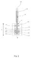
- FIG. 2 shows a milling tool being provided with a plurality of widenings
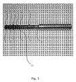
- FIG. 3 is a photograph of a milling tool in a side-view
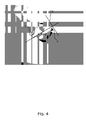
- FIG. 4 is a photograph of the milling tool in a close-up view seen from a proximate end of the milling tool.
- Fig. 1 illustrates an embodiment of the invention, a milling tool 1 for providing a plurality of widenings in a hole 2 at predetermined depths of the hole.
- the milling tool has a shaft 3 with a thickness 4 and a centre axis 5 and the shaft is provided with a plurality of cutting elements 7 protruding in a radial direction from the shaft 3.
- the thickness of the shaft together with the radial protrusion of the cutting elements from the shaft are smaller than a diameter D of the hole 2, where the widenings are to be formed.
- the plurality of widenings are formed by performing a rotation of the shaft around the centre axis 5 while also performing a radial displacement of the shaft centre axis relative to a centre axis A of the hole.
- the cutting elements 7 are arranged along the length L of the shaft at predetermined axial positions.
- the cutting elements are arranged along the shaft along two helixes 8.
- the cutting elements 7 are arranged in sets of at least two at a given axial position along the length of the shaft on each of the two helixes 8 and are possibly arranged 180 degrees spaced apart from each other, i.e. diagonally.
- the helixes extend along variable helix angles, the helixes will not be spaced apart by 180 degrees, but will be spaced apart at a different angle along at least some of the extension of the helixes. Also, if three or four or more helixes are provided, the angle between the helixes will not be 180 degrees, but will be much smaller than 180 degrees, perhaps 120 degrees or 90 degrees or even a smaller angle.
- the cutting elements are arranged in sets of one or in sets of more than two at a given axial position along the length of the shaft on each of the two helixes 8.
- the cutting elements are preferably arranged angularly equidistant spaced apart from each other along the circumference of the shaft.
- FIG. 2 shows the milling tool 1 when inserted inside the hole 2, where the widenings are to be formed, at a predetermined depth within the hole.
- the work-piece with the hole is shown schematically in a cross sectional view through the centre axis A of the hole 2.
- the milling tool When the milling tool performs a rotation of the shaft around the centre axis 5, as indicated by the curved arrow 13, and at the same time a radial displacement of the shaft, as indicated by the two straight arrows 14, the plurality of widenings 11 are provided.
- the radial displacement of the milling tool 1 may be alternating in both of the directions at the same time indicated by the two straight arrows.
- each of the plurality of widenings 11 are situated at certain depths of the hole 2.
- the widenings 11 are grooves or annular widenings along the complete inner circumference of the hole.
- the widenings may only be provided along a limited circumferential part of the inner circumference.
- the hole 2 is a through-going hole 2 but may also be a blind hole (not shown).
- the figure shows that the milling tool is held at a relative depth L of the milling tool 1 within the hole 2 and aligned parallel with the centre axis A of the hole and the centre axis 5 of the shaft 3.
- the milling tool 1 is intended for being inserted in an automated milling machine (not shown) for providing the rotation and the radial displacement of the milling tool.
- FIG. 3 and 4 are photographs of the milling tool 1 as described in FIG. 1 and 2 in a side view and a view seen from a proximate end of the milling tool, respectively.
- the proximate end of the milling tool is the end intended for being inserted into the hole, i.e. the end opposite a distant end at which the tool is intended for being mounted in the milling machine.
- Two cutting elements both positioned at the same position along the length of the milling tool, namely at the front end, are arranged 180 degrees spaced apart from each other.
- a given chord 20 at an outer circumference of a circle formed by the outer radial surface of the cutting elements when rotated, only one cutting element is provided along the length of the shaft.
Landscapes
- Engineering & Computer Science (AREA)
- Mechanical Engineering (AREA)
- Milling Processes (AREA)
Priority Applications (2)
| Application Number | Priority Date | Filing Date | Title |
|---|---|---|---|
| EP07114960A EP2080575A1 (fr) | 2007-08-24 | 2007-08-24 | Outil de fraisage pour agrandir un trou |
| PCT/DK2008/050210 WO2009026932A1 (fr) | 2007-08-24 | 2008-08-22 | Outil de fraisage destiné à réaliser des élargissements dans un trou |
Applications Claiming Priority (1)
| Application Number | Priority Date | Filing Date | Title |
|---|---|---|---|
| EP07114960A EP2080575A1 (fr) | 2007-08-24 | 2007-08-24 | Outil de fraisage pour agrandir un trou |
Publications (1)
| Publication Number | Publication Date |
|---|---|
| EP2080575A1 true EP2080575A1 (fr) | 2009-07-22 |
Family
ID=39103015
Family Applications (1)
| Application Number | Title | Priority Date | Filing Date |
|---|---|---|---|
| EP07114960A Ceased EP2080575A1 (fr) | 2007-08-24 | 2007-08-24 | Outil de fraisage pour agrandir un trou |
Country Status (2)
| Country | Link |
|---|---|
| EP (1) | EP2080575A1 (fr) |
| WO (1) | WO2009026932A1 (fr) |
Cited By (1)
| Publication number | Priority date | Publication date | Assignee | Title |
|---|---|---|---|---|
| DE102021112363A1 (de) | 2021-05-12 | 2022-11-17 | Audi Aktiengesellschaft | Bearbeitungs-Werkzeug zur Schneid- und/oder Formbearbeitung der Innenwandung einer Werkstück-Bohrung |
Families Citing this family (4)
| Publication number | Priority date | Publication date | Assignee | Title |
|---|---|---|---|---|
| DE102019200829B4 (de) * | 2019-01-24 | 2025-02-13 | Audi Ag | Rotations-Werkzeug zur Erzeugung eines Honfreigangs |
| DE102019201246B4 (de) * | 2019-01-31 | 2023-12-14 | Audi Ag | Verfahren zum mechanischen Aufrauen einer Werkstück-Zylinderbohrung mittels eines Aufrau-Werkzeugs |
| DE102019109492B3 (de) * | 2019-04-10 | 2020-09-03 | Audi Ag | Rotations-Fräswerkzeug |
| DE102020211664A1 (de) * | 2020-09-17 | 2022-03-17 | Ford Global Technologies, Llc | Schneidwerkzeug |
Citations (5)
| Publication number | Priority date | Publication date | Assignee | Title |
|---|---|---|---|---|
| GB191103494A (en) * | 1910-03-01 | 1911-04-20 | Otto Unterloff | Improvements in Milling Cutters. |
| US2782490A (en) * | 1952-06-27 | 1957-02-26 | Cincinnati Milling Machine Co | Milling cutter |
| EP0059979A2 (fr) * | 1981-03-11 | 1982-09-15 | Gebr. Heller Maschinenfabrik GmbH | Machine pour le fraisage de rainures dans la paroi d'alésages de pièces |
| US5934847A (en) * | 1992-09-15 | 1999-08-10 | Sandvik Ab | Method of machining composites |
| EP1772220A1 (fr) * | 2005-10-08 | 2007-04-11 | MTU Aero Engines GmbH | Procédé de fraisage |
-
2007
- 2007-08-24 EP EP07114960A patent/EP2080575A1/fr not_active Ceased
-
2008
- 2008-08-22 WO PCT/DK2008/050210 patent/WO2009026932A1/fr not_active Ceased
Patent Citations (5)
| Publication number | Priority date | Publication date | Assignee | Title |
|---|---|---|---|---|
| GB191103494A (en) * | 1910-03-01 | 1911-04-20 | Otto Unterloff | Improvements in Milling Cutters. |
| US2782490A (en) * | 1952-06-27 | 1957-02-26 | Cincinnati Milling Machine Co | Milling cutter |
| EP0059979A2 (fr) * | 1981-03-11 | 1982-09-15 | Gebr. Heller Maschinenfabrik GmbH | Machine pour le fraisage de rainures dans la paroi d'alésages de pièces |
| US5934847A (en) * | 1992-09-15 | 1999-08-10 | Sandvik Ab | Method of machining composites |
| EP1772220A1 (fr) * | 2005-10-08 | 2007-04-11 | MTU Aero Engines GmbH | Procédé de fraisage |
Cited By (1)
| Publication number | Priority date | Publication date | Assignee | Title |
|---|---|---|---|---|
| DE102021112363A1 (de) | 2021-05-12 | 2022-11-17 | Audi Aktiengesellschaft | Bearbeitungs-Werkzeug zur Schneid- und/oder Formbearbeitung der Innenwandung einer Werkstück-Bohrung |
Also Published As
| Publication number | Publication date |
|---|---|
| WO2009026932A1 (fr) | 2009-03-05 |
Similar Documents
| Publication | Publication Date | Title |
|---|---|---|
| US7648316B2 (en) | Forstner drill bit | |
| KR100694578B1 (ko) | 밀링 툴 및 그 제작공정 | |
| EP3031557B1 (fr) | Dispositif de coupe et outil de coupe comprenant celui-ci | |
| CN106457424B (zh) | 具有改善型连接件的切削刀头 | |
| US20100158626A1 (en) | Drill and drilling method for workpiece | |
| EP2080575A1 (fr) | Outil de fraisage pour agrandir un trou | |
| US10065250B2 (en) | Drill and method of drilling a hole | |
| EP3219424B1 (fr) | Outil de perçage orbital à géométrie double usinage/brunissage | |
| US11458551B2 (en) | End mill | |
| CN105209190B (zh) | 麻花钻及制造方法 | |
| EP2910326B1 (fr) | Outil de matériau empilé et procédé d'usinage | |
| CN108723510A (zh) | 去毛刺装置和包括所述去毛刺装置的cnc齿轮切削机 | |
| US20170326653A1 (en) | Drill | |
| US20210154728A1 (en) | Manufacturing Process, Tool Stand, and Drill Bit | |
| CN109689261B (zh) | 螺纹形成刀具 | |
| US10252321B2 (en) | Twist drill and production method | |
| EP3354389A1 (fr) | Procédé d'usinage de chemins de roulement à billes des joints homocinétiques | |
| JP2006159210A (ja) | パイプの孔開け用パンチ及び孔開け方法 | |
| JP2015024471A (ja) | ボールねじ用ナットの加工工具及び加工方法 | |
| US11020818B2 (en) | Connection element for an interlocking connection to at least one component | |
| EP3153268B1 (fr) | Poinçon de coupe | |
| KR20040066715A (ko) | 드릴 | |
| US20190184475A1 (en) | Single-Edged Milling Tool | |
| US20240399477A1 (en) | Stepped rotary broaches and methods and systems employing same | |
| JP7657505B1 (ja) | 切削工具 |
Legal Events
| Date | Code | Title | Description |
|---|---|---|---|
| PUAI | Public reference made under article 153(3) epc to a published international application that has entered the european phase |
Free format text: ORIGINAL CODE: 0009012 |
|
| AK | Designated contracting states |
Kind code of ref document: A1 Designated state(s): AT BE BG CH CY CZ DE DK EE ES FI FR GB GR HU IE IS IT LI LT LU LV MC MT NL PL PT RO SE SI SK TR |
|
| AX | Request for extension of the european patent |
Extension state: AL BA HR MK RS |
|
| STAA | Information on the status of an ep patent application or granted ep patent |
Free format text: STATUS: THE APPLICATION HAS BEEN REFUSED |
|
| 18R | Application refused |
Effective date: 20090425 |