EP2080599B1 - Machine destinée à couper des aliments en bandes ou en dés - Google Patents
Machine destinée à couper des aliments en bandes ou en dés Download PDFInfo
- Publication number
- EP2080599B1 EP2080599B1 EP08105903A EP08105903A EP2080599B1 EP 2080599 B1 EP2080599 B1 EP 2080599B1 EP 08105903 A EP08105903 A EP 08105903A EP 08105903 A EP08105903 A EP 08105903A EP 2080599 B1 EP2080599 B1 EP 2080599B1
- Authority
- EP
- European Patent Office
- Prior art keywords
- grid
- stabilizing
- cutting
- knives
- cutting grid
- Prior art date
- Legal status (The legal status is an assumption and is not a legal conclusion. Google has not performed a legal analysis and makes no representation as to the accuracy of the status listed.)
- Not-in-force
Links
- 238000005520 cutting process Methods 0.000 title claims description 68
- 235000013305 food Nutrition 0.000 title claims description 9
- 229910001220 stainless steel Inorganic materials 0.000 claims abstract description 4
- 239000010935 stainless steel Substances 0.000 claims abstract description 4
- 230000000087 stabilizing effect Effects 0.000 claims description 137
- 239000000463 material Substances 0.000 claims description 37
- 238000009760 electrical discharge machining Methods 0.000 claims description 3
- 238000009966 trimming Methods 0.000 claims 1
- 230000006641 stabilisation Effects 0.000 abstract description 8
- 238000011105 stabilization Methods 0.000 abstract description 8
- 230000006835 compression Effects 0.000 description 4
- 238000007906 compression Methods 0.000 description 4
- 238000004140 cleaning Methods 0.000 description 3
- 208000034656 Contusions Diseases 0.000 description 2
- 240000006829 Ficus sundaica Species 0.000 description 2
- 238000005452 bending Methods 0.000 description 2
- 238000010276 construction Methods 0.000 description 2
- 230000000694 effects Effects 0.000 description 2
- 238000004519 manufacturing process Methods 0.000 description 2
- 239000000725 suspension Substances 0.000 description 2
- 230000002411 adverse Effects 0.000 description 1
- 230000008878 coupling Effects 0.000 description 1
- 238000010168 coupling process Methods 0.000 description 1
- 238000005859 coupling reaction Methods 0.000 description 1
- 238000006073 displacement reaction Methods 0.000 description 1
- 238000003780 insertion Methods 0.000 description 1
- 230000037431 insertion Effects 0.000 description 1
- 238000000034 method Methods 0.000 description 1
- 230000002787 reinforcement Effects 0.000 description 1
- 230000002441 reversible effect Effects 0.000 description 1
- 238000007493 shaping process Methods 0.000 description 1
- 239000003381 stabilizer Substances 0.000 description 1
- 230000001960 triggered effect Effects 0.000 description 1
- 230000000007 visual effect Effects 0.000 description 1
Images


Classifications
-
- B—PERFORMING OPERATIONS; TRANSPORTING
- B26—HAND CUTTING TOOLS; CUTTING; SEVERING
- B26D—CUTTING; DETAILS COMMON TO MACHINES FOR PERFORATING, PUNCHING, CUTTING-OUT, STAMPING-OUT OR SEVERING
- B26D3/00—Cutting work characterised by the nature of the cut made; Apparatus therefor
- B26D3/18—Cutting work characterised by the nature of the cut made; Apparatus therefor to obtain cubes or the like
- B26D3/185—Grid like cutters
-
- B—PERFORMING OPERATIONS; TRANSPORTING
- B26—HAND CUTTING TOOLS; CUTTING; SEVERING
- B26D—CUTTING; DETAILS COMMON TO MACHINES FOR PERFORATING, PUNCHING, CUTTING-OUT, STAMPING-OUT OR SEVERING
- B26D1/00—Cutting through work characterised by the nature or movement of the cutting member or particular materials not otherwise provided for; Apparatus or machines therefor; Cutting members therefor
- B26D1/0006—Cutting members therefor
Definitions
- the invention relates to a machine for cutting food into strips or cubes, with an inserting area for the food to be cut, a cutting device and a feed device, with which the food from the loading area in the direction of the cutting device can be advanced, the first and a second Having knife gate each with a plurality of mutually parallel and spaced apart elongated knife, the second knife gate is provided with stabilizing webs, the passages for the stabilizing webs crossing blades of the second knife gate and wherein viewed in the feed direction behind the second knife gate a is arranged by this releasable stabilizing grid, which has a plurality of crossing stabilizing webs, viewed in the feed direction in each case with the knives of the first knife gate and / or the knives of the second knife
- the stabilizing bars of the stabilizing grid are fastened at opposite ends to a grid frame, which is fastened to a holding frame of the second knife gate.
- Machines for cutting foods into strips or cubes have long been known and, for example, in the document DE 1247572 B described. Such machines are often designed as so-called cube scissors in which the present life is mediumly inserted into an elongated insertion shaft forming a feed area, a so-called magazine.
- a feed device the Schnei dgut is then advanced through an outlet cross section of the feed to a cutter, which consists of two crosswise one behind the other, movable knife gates, in which a plurality of gate blades are mounted parallel to each other.
- the movable holder of the knife gate on the support frame of the cutting machine via two sliding rods, which are arranged in the longitudinal direction parallel to the Gattermessern.
- the material to be cut is sliced on the first knife gate seen in the feed direction and then in strips by the second knife gate cut a preferably square cross-section.
- a transverse cutting knife rotating perpendicularly to the feed direction of the material to be cut, short portions, often in the form of cubes, are finally produced from the food cut into strips by the two knife guards.
- a disadvantage of these cutting machines is that the material to be cut often adheres to the Gattermessern. Therefore, by the movement of the knife gate, and in particular by the movement of the second knife gate, there may be a deformation of the cut strips, so that they no longer come straight out of the cutter and thus can not be cut straight by the cross cutting knife , Without suffering any loss of quality, however, this suffers from the visual impression of the product, which can affect its sale.
- a guide grid between the second knife gate and the cross-cutting blade described which serves the straight-line guidance of emerging from the second knife gate, strip-shaped Schneidguts. This is to ensure that the cross-cutting blade can perform exact straight and clean cuts for the final desired strip or cube shape of the cutting material.
- the guide grid is intended to be formed together with the holding frame of the second knife gate as a one-piece unit or as a separately attachable unit.
- this deflection effect can also occur in the stabilizing webs of the second knife gate, since the sliced after passing through the first knife gate there cutting material in its disc normal direction, which coincides with the direction of movement of the second knife gate, a much higher mobility than before the first knife gate ,
- the guide grid for easier assembly and easier cleaning of the cutting device formed in an advantageous manner as a separately attachable unit, it may happen that by the possible lateral deflection of the blades or the stabilizing webs of the second knife gate this no longer completely with the webs of the guide grid aligned.
- the material to be cut can then be pressed in places frontally against the webs of the guide lattice and thereby suffer the just unwanted compression and crushing. This also means that the required feed pressure for the material to be cut must be increased in an undesirable manner.
- the object of the present invention is therefore to construct and install a guiding or stabilizing grid between the second knife gate and the cross cutting knife so that the knives and the stabilizing webs of the second knife gate have a high lateral stability or that their lateral deflection is prevented.
- the stabilizing grid should also be easy to produce and ensure easy cleaning and easy assembly of the cutting device.
- the stabilizing webs of the stabilizing grid at their front, the second knife gate facing end surfaces with back surfaces of the blades of the second knife gate and / or back surfaces of the stabilizing webs of the second knife gate in at least one Direction perpendicular to the feed direction are connected directly in a force-transmitting manner and in particular in the form of a positive and / or material connection.
- the stabilizing grid is composed of a plurality of fixedly connected stabilizing webs which intersect at right angles and thus form rectangular openings through which the strip-shaped material to be cut is passed.
- the back sides of the blades of the second blade gate or of the stabilizing webs of the second blade gate may undergo a frictional connection with the stabilizing webs of the stabilizing screen in a deflection in the feed direction, but this is not sufficient to avoid deflections perpendicular to the feed direction.
- the material connection provided according to the invention as an alternative to the positive connection is only applicable where there is no relative movement between the components to be coupled, ie at the stationary stabilizing webs of the second knife gate with the likewise stabilizing webs of the stabilizing grid.
- On the back of the blades of the second knife gate on the other hand, there must be a form-locking connection with the stabilizing webs of the stabilizing grid.
- the force-transmitting connection between the back surfaces of the stabilizing webs of the second knife gate and the end faces of the stabilizing webs of the stabilizing grid can also be formed as a cohesive connection.
- the force-transmitting connection should be between the back surfaces of the blades of the second knife gate or between the back surfaces of the stabilizing webs of the second knife gate on the one hand and the end faces of the stabilizing webs of the stabilizing grid on the other hand positively to achieve a safe and easily reversible and recoverable coupling between the two components ,
- connection for example in the form of tongue and groove connection, should in this case be shaped in such a way that a displacement of the blades or of the stabilizing webs of the second blade gate in a direction perpendicular to their longitudinal direction is counteracted.
- a group of stabilizing webs of the stabilizing grid oriented parallel to one another should have slots in which rear edge strips of the knives or stabilizing webs of the second knife gate running perpendicular to the slotted stabilizing webs engage. This ensures that, depending on whether neither the blades nor the stabilizing webs of the second blade gate can bend perpendicular to their longitudinal direction.
- the slots formed in the stabilizing webs of the stabilizing grid continue in a line, preferably also in opposite frame legs of the grid frame of the stabilizing grid.
- the knives or the stabilizing webs of the second knife gate additionally receive particular lateral hold via their rear edge strips.
- breakthroughs in the stabilizing webs of the second knife gate allow the passing of the knife of the second knife gate arranged perpendicular to the stabilizing webs.
- the apertures are each circumferentially closed, so that the back surfaces of the blades of the second knife gate can be supported during cutting on the narrow sides of the walls bounding the knife back faces of the walls delimiting the respective apertures, whereby a further increase in strength also occurs in the feed direction.
- Stainless steel should preferably be used as the material for the stabilizing grid, which is particularly suitable for such cutting devices because of its material properties.
- the grid itself should be made of one piece, which due to the high manufacturing accuracy shaping of the stabilizing webs should be done by spark erosion.
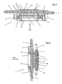
- FIG. 1 is a cutting device 1, consisting of a in the feed direction (VSR) of the material to be cut seen first knife gate 2, followed by a rotated by 90 ° second knife gate 3 and further followed by a stabilizing grid 8, shown in perspective; a plan view of the cutting device 1 opposite to the feed direction of the material to be cut shows FIG. 2 ,
- the gate gates 2 and 3 are each parallel in the longitudinal direction and arranged at a distance from each other a plurality of blades 4, which are detachably connected via a suspension 5 with the knife gates 2 and 3 respectively.
- sliding bars 6 are furthermore fastened in the cutting direction parallel to the knives 4 by means of fastening screws 10, which in turn are slidably mounted in bearing bores 22 of a holding frame 14.
- fastening screws 10 which in turn are slidably mounted in bearing bores 22 of a holding frame 14.
- the knife gates 2 and 3 are driven in an oscillating manner at their ends formed to form anchors 7 via an eccentric, not shown here, in each case in the longitudinal direction of the knives 4.
- the preferably square stabilizing grid 8 consists of a plurality of stabilizing webs 18a and 18b bordered by a grid frame 13, which are arranged so as to be grid-connected with one another and with the grid frame in such a way that the stabilizing webs 18a intersect at right angles with the stabilizing webs 18b.
- the stabilizing webs 18a of the stabilizing grid 8 are aligned with the knives 4 of the knife gate 3, while the stabilizing webs 18b are aligned with the stabilizing webs 12 of the second knife gate 3 aligned with the knives 4 of the first knife gate 2.
- the stabilizing grid 8 is releasably secured by screws 9 on the support frame 14 so that the screw heads of the screws 9 are completely sunk in the assembled state in the lattice frame 13. This ensures trouble-free cutting of the strip-shaped material to be cut by the cross-cutting blade.
- FIG. 3 shows a section through the cutter 1 on the line III -III according to FIG. 2 ,
- the section allows a view along the knife 4 of the first knife gate 2 on a transverse thereto, cut in its longitudinal direction knife 4 of the second knife gate 3, which is passed through openings 11 in the stabilizing webs 12 of the second knife gate 3.
- the breakthroughs 11 are better recognizable because of FIG. 5 shown enlarged.
- the knives 4 of the first knife gate 2 are precisely aligned with the stabilizing webs 12 of the second knife gate 3 and are supported in the feed direction of the material to be cut with back surfaces 16 on end faces 15 of the stabilizing webs 12 of the second knife gate 3 from.
- the cutting device 1 is able to easily cut even hard or frozen material to be cut.
- the knives 4 of the second knife gate 3 are supported with their back surfaces 16 on end faces 19 of the stabilizing webs 18a of the stabilizing grid 8, the knives 4 also being exactly aligned with the stabilizing webs 18a, and secondly supporting themselves with their back surfaces 16 the back surfaces 16 facing narrow sides of the circumferentially closed openings 11 from (s. FIG. 4 ).
- the blades 4 of the second blade gate 3 could bend slightly due to their length and small thickness transversely to the feed direction of the material to be cut. This would lead to the blades 4 of the second blade gate 3 no longer being precisely aligned with the stabilizing webs 18a of the stabilizing grid 8, whereby the material to be cut would be pressed partially against the end faces 19 of these stabilizing webs 18a. In this case, the cutting material could suffer compression and bruising and a clean, straight cutting by the cross-cutting blade would then no longer possible. Therefore, have the openings 11 in the stabilizing webs 12 of the second blade gate 3, as shown FIG. 4 it can be seen, so narrow openings that the blades 4 of the second blade gate 3 can be supported on the longitudinal sides of the openings 11 and thus a permanent exact alignment of these blades 4 is ensured with the stabilizing webs 18a.
- the stabilizing webs 12 of the second knife gate 3 are aligned with the stabilizing webs 18b of the stabilizing grid 8.
- the stabilizing webs 12 via back surfaces 17 in direct positive engagement with these stabilizing webs 18b.
- the movement of the material to be cut triggered by friction on the knives 4 of the second knife gate 3 could likewise lead to lateral deflections of the stabilizing webs 12 of the second knife gate 3 and thus impair the exact alignment of these stabilizing webs 12 with the stabilizing webs 18b of the stabilizing grid 8. This would then also lead to compression and crushing of the material to be cut on the stabilizing webs 18b of the stabilizing grid 8.
- the stabilizing grid 8 As a material for the stabilizing grid 8 stainless steel is provided, which still has a high strength, even at low material thicknesses. Since the stabilizing webs 18 are formed very thin in accordance with the knives 4 and the stabilizing webs 12, the stabilizing grid 8 is therefore not made of several individual parts but in one piece. Because of the complex structure of the workpiece and the required high dimensional accuracy, it is therefore provided to produce the stabilizing grid 8 preferably via the method of spark erosion.
Landscapes
- Life Sciences & Earth Sciences (AREA)
- Forests & Forestry (AREA)
- Engineering & Computer Science (AREA)
- Mechanical Engineering (AREA)
- Confectionery (AREA)
- Food-Manufacturing Devices (AREA)
- Manufacture Of Wood Veneers (AREA)
- Nonmetal Cutting Devices (AREA)
- Knives (AREA)
Claims (8)
- Machine destinée à tailler des aliments en bandes ou en dés, avec une zone de chargement de l'aliment à tailler, un dispositif de coupe (1) et un dispositif d'avance, à l'aide duquel l'aliment peut être poussé à partir de la zone de chargement en direction du dispositif de coupe (1), qui comporte un premier et un deuxième treillis de lames (2, 3) avec chacun une pluralité de lames (4) allongées, s'étendant à la parallèle les unes des autres et disposées avec un écart les unes par rapport aux autres, le deuxième treillis de lames (3) étant muni de barrettes stabilisatrices (12) qui comportent des ajours (11) pour les lames (4) du deuxième treillis de lames (3) croisant les barrettes stabilisatrices (12) et considéré en direction d'avance, derrière le deuxième treillis de lames (3) étant disposé un treillis stabilisateur (8) amovible sur celui-ci, qui comporte une pluralité de barrettes stabilisatrices (18a, 18b) qui se croisent, qui considérées en direction d'avance sont chaque fois alignées sur les lames (4) du premier treillis de lames (2) et/ou sur les lames (4) du deuxième treillis de lames (3), alors que par ailleurs, les barrettes stabilisatrices (18a, 18b) du treillis stabilisateur (8) sont fixées par l'extrémité opposée sur un cadre de treillis (13), qui est fixé quant à lui sur un cadre de maintien (14) du deuxième treillis de lames (3), caractérisée en ce que les barrettes stabilisatrices (18a, 18b) du treillis stabilisateur (8) sont reliées sur leurs surfaces frontales antérieures (19), faisant face au deuxième treillis de lames (3) avec des surfaces postérieures (16) des lames (4) du deuxième treillis de lames (3) et/ou avec des surfaces postérieures (17) des barrettes stabilisatrices (12) du deuxième treillis de lames (3) dans au moins une direction, à la perpendiculaire de la direction d'avance, directement de sorte à transmettre les forces, notamment par complémentarité de forme et/ou par liaison de matière.
- Machine selon la revendication 1, caractérisée en ce que les barrettes stabilisatrices (18a, 18b) du treillis stabilisateur (8) sont reliées par complémentarité de forme avec les barrettes stabilisatrices (12) du deuxième treillis de lames (3) et/ou avec les lames (4) du deuxième treillis de lames (3).
- Machine selon la revendication 1 ou 2, caractérisée en ce que les barrettes stabilisatrices (18a, 18b) du treillis stabilisateur (8) sont reliées avec les barrettes stabilisatrices (12) du deuxième treillis de lames (3) et/ou avec les lames (4) du deuxième treillis de lames (3), de sorte à contrecarrer un déplacement des barrettes stabilisatrices (12) et/ou des lames (4) du deuxième treillis de lames, chaque fois dans une direction à la perpendiculaire de leur direction longitudinale.
- Machine selon l'une quelconque des revendications 1 à 3, caractérisée en ce qu'un groupe de barrettes stabilisatrices (18a) s'étendant à la parallèle les unes des autres du treillis stabilisateur (8) comporte des encoches, dans lesquelles les barrettes stabilisatrices (12) du deuxième treillis de lames (3) ou des lames (4) du deuxième treillis de lames (3) s'étendant à la perpendiculaire des barrettes stabilisatrices (18a) munies d'encoches du treillis stabilisateur (8) s'engagent par des bandes postérieures de bordure.
- Machine selon l'une quelconque des revendications 1 à 4, caractérisée en ce que le cadre de treillis (13) comporte des branches de cadre opposées, qui sont munies d'encoches (21) dans lesquelles s'engagent les lames (4) et/ou les barrettes stabilisatrices (12) du deuxième treillis de lames (3).
- Machine selon l'une quelconque des revendications 1 à 4, caractérisée en ce que les barrettes stabilisatrices (12) du deuxième treillis de lames (3) comportent sur leur périphérie des ajours fermés, à travers lesquels sont guidées les lames (4) du deuxième treillis de lames (3).
- Machine selon la revendication 5, caractérisée en ce qu'en mode coupe de la machine, les lames (4) du deuxième treillis de lames (3) s'appuient par leurs surfaces postérieures (16) chaque fois sur un côté étroit qui leur fait face d'une paroi délimitant l'ajour concerné.
- Machine selon l'une quelconque des revendications 1 à 6, caractérisée en ce que le treillis stabilisateur (8) est conçu en monobloc et fabriqué de préférence en acier fin, de préférence par électroérosion.
Applications Claiming Priority (1)
| Application Number | Priority Date | Filing Date | Title |
|---|---|---|---|
| DE102008005461A DE102008005461A1 (de) | 2008-01-21 | 2008-01-21 | Stabilisierungsgitter für Schneidmaschine |
Publications (2)
| Publication Number | Publication Date |
|---|---|
| EP2080599A1 EP2080599A1 (fr) | 2009-07-22 |
| EP2080599B1 true EP2080599B1 (fr) | 2010-05-19 |
Family
ID=40344619
Family Applications (1)
| Application Number | Title | Priority Date | Filing Date |
|---|---|---|---|
| EP08105903A Not-in-force EP2080599B1 (fr) | 2008-01-21 | 2008-12-01 | Machine destinée à couper des aliments en bandes ou en dés |
Country Status (5)
| Country | Link |
|---|---|
| EP (1) | EP2080599B1 (fr) |
| AT (1) | ATE468207T1 (fr) |
| DE (2) | DE102008005461A1 (fr) |
| DK (1) | DK2080599T3 (fr) |
| ES (1) | ES2345519T3 (fr) |
Cited By (1)
| Publication number | Priority date | Publication date | Assignee | Title |
|---|---|---|---|---|
| DE102019109712B3 (de) | 2019-04-12 | 2020-06-18 | Tpv Gmbh | Vorrichtung und Verfahren zum Schneiden eines Lebensmittels in Streifen oder Würfel |
Families Citing this family (4)
| Publication number | Priority date | Publication date | Assignee | Title |
|---|---|---|---|---|
| CN114619516A (zh) * | 2022-02-28 | 2022-06-14 | 深圳灵感之茶科技有限公司 | 切丁组件和切丁机 |
| CN114589752A (zh) * | 2022-03-01 | 2022-06-07 | 深圳灵感之茶科技有限公司 | 切丁机 |
| CN114589751A (zh) * | 2022-03-01 | 2022-06-07 | 深圳灵感之茶科技有限公司 | 驱动机构和切丁机 |
| CN114589753A (zh) * | 2022-03-01 | 2022-06-07 | 深圳灵感之茶科技有限公司 | 切丁机 |
Family Cites Families (3)
| Publication number | Priority date | Publication date | Assignee | Title |
|---|---|---|---|---|
| DE1247572B (de) | 1966-03-23 | 1967-08-17 | Ernst Holz | Wuerfelschneideinrichtung fuer Speck und andere Lebensmittel |
| DE2054933A1 (de) * | 1970-11-07 | 1972-05-10 | Reifenhäuser, Toni, 5231 Burglahr | Schneidmaschine |
| DE19832945C2 (de) | 1998-07-22 | 2000-09-14 | Achim Holz | Vorrichtung zum Schneiden von Lebensmitteln |
-
2008
- 2008-01-21 DE DE102008005461A patent/DE102008005461A1/de not_active Withdrawn
- 2008-12-01 DK DK08105903.2T patent/DK2080599T3/da active
- 2008-12-01 AT AT08105903T patent/ATE468207T1/de active
- 2008-12-01 EP EP08105903A patent/EP2080599B1/fr not_active Not-in-force
- 2008-12-01 DE DE502008000684T patent/DE502008000684D1/de active Active
- 2008-12-01 ES ES08105903T patent/ES2345519T3/es active Active
Cited By (2)
| Publication number | Priority date | Publication date | Assignee | Title |
|---|---|---|---|---|
| DE102019109712B3 (de) | 2019-04-12 | 2020-06-18 | Tpv Gmbh | Vorrichtung und Verfahren zum Schneiden eines Lebensmittels in Streifen oder Würfel |
| EP3733365A1 (fr) | 2019-04-12 | 2020-11-04 | TPV GmbH | Dispositif de coupe d'une denrée alimentaire en lanières ou en cubes et procédé pour le démontage d'une grille double |
Also Published As
| Publication number | Publication date |
|---|---|
| DE102008005461A9 (de) | 2009-11-12 |
| DK2080599T3 (da) | 2010-08-09 |
| ES2345519T3 (es) | 2010-09-24 |
| DE502008000684D1 (de) | 2010-07-01 |
| EP2080599A1 (fr) | 2009-07-22 |
| DE102008005461A1 (de) | 2009-07-30 |
| ATE468207T1 (de) | 2010-06-15 |
Similar Documents
| Publication | Publication Date | Title |
|---|---|---|
| EP2208566B1 (fr) | Outil de coupe avec couteau de coupe par enlèvement et méthode pour attacher le couteau de coupe à l'outil de coupe | |
| EP2080599B1 (fr) | Machine destinée à couper des aliments en bandes ou en dés | |
| WO2011057726A2 (fr) | Lame de coupe d'un dispositif de coupe de tabac | |
| DE102015000983B4 (de) | Messerkopf für eine Produktschneidemaschine | |
| EP0221340B1 (fr) | Cadre de fixation pour couteaux à grilles | |
| DE2923003C2 (de) | Schneidmaschine für Lebensmittel | |
| DE102005019945B4 (de) | Trägerwerkzeug für eine Schneidplatte mit zwei Schneiden und Schneidplatte mit zwei Schneiden | |
| EP3359356A1 (fr) | Dispositif pour couper un tronçon d'aliments | |
| DE3216092C2 (de) | Zerkleinerer für Material aus Kunststoff | |
| EP1300221A2 (fr) | Dispositif pour couper un matériau d'emballage matelassé | |
| DE20019878U1 (de) | Maschine zum Schneiden von Lebensmitteln wie Fleisch, Wurst, Käse o.dgl. in Streifen oder Würfel | |
| EP0531649B1 (fr) | Dispositif de coupe comprenant des cadres supportant des couteaux pour couper du lard, de la viande, des saucisses ou des produits similaires | |
| DE1552612B2 (de) | Schneidemaschine fuer stabmaterial | |
| DE102019110956B3 (de) | Vorrichtung zum Schneiden und/oder Raspeln von Lebensmitteln | |
| EP0412488B1 (fr) | Dispositif pour la coupe en tranches de fruits ou légumes | |
| DE804861C (de) | Saegerahmen fuer Gattersaegen | |
| DE102011112125A1 (de) | Vorrichtung zum Verlegen einer Materialbahn | |
| EP2072196B1 (fr) | Guidage de barre coulissante pour machine de coupe | |
| DE3243448C2 (de) | Vorrichtung zum Schneiden von Lebensmitteln | |
| DE8505062U1 (de) | Messerkopf für eine Fleischschneidemaschine | |
| DD156232A1 (de) | Vorrichtung zum schneiden von lebensmitteln,insbesondere in streifen,wuerfeln od.dgl. | |
| DE3012493A1 (de) | Vorrichtung zum schneiden von dichtungsprofilen aus elastormeren werkstoffen auf gehrung | |
| EP1854604B1 (fr) | Dispositif d'attelage en coin pour le serrage de couteaux en plaque dans des têtes porte-lames | |
| DE1653137C3 (fr) | ||
| EP1632325A1 (fr) | chaîne de sciage pour scies à chaîne |
Legal Events
| Date | Code | Title | Description |
|---|---|---|---|
| PUAI | Public reference made under article 153(3) epc to a published international application that has entered the european phase |
Free format text: ORIGINAL CODE: 0009012 |
|
| AK | Designated contracting states |
Kind code of ref document: A1 Designated state(s): AT BE BG CH CY CZ DE DK EE ES FI FR GB GR HR HU IE IS IT LI LT LU LV MC MT NL NO PL PT RO SE SI SK TR |
|
| AX | Request for extension of the european patent |
Extension state: AL BA MK RS |
|
| 17P | Request for examination filed |
Effective date: 20090925 |
|
| GRAP | Despatch of communication of intention to grant a patent |
Free format text: ORIGINAL CODE: EPIDOSNIGR1 |
|
| AKX | Designation fees paid |
Designated state(s): AT BE BG CH CY CZ DE DK EE ES FI FR GB GR HR HU IE IS IT LI LT LU LV MC MT NL NO PL PT RO SE SI SK TR |
|
| GRAS | Grant fee paid |
Free format text: ORIGINAL CODE: EPIDOSNIGR3 |
|
| GRAA | (expected) grant |
Free format text: ORIGINAL CODE: 0009210 |
|
| AK | Designated contracting states |
Kind code of ref document: B1 Designated state(s): AT BE BG CH CY CZ DE DK EE ES FI FR GB GR HR HU IE IS IT LI LT LU LV MC MT NL NO PL PT RO SE SI SK TR |
|
| REG | Reference to a national code |
Ref country code: GB Ref legal event code: FG4D Free format text: NOT ENGLISH |
|
| REG | Reference to a national code |
Ref country code: CH Ref legal event code: EP |
|
| REG | Reference to a national code |
Ref country code: IE Ref legal event code: FG4D Free format text: LANGUAGE OF EP DOCUMENT: GERMAN |
|
| REF | Corresponds to: |
Ref document number: 502008000684 Country of ref document: DE Date of ref document: 20100701 Kind code of ref document: P |
|
| REG | Reference to a national code |
Ref country code: DK Ref legal event code: T3 |
|
| REG | Reference to a national code |
Ref country code: NL Ref legal event code: VDEP Effective date: 20100519 |
|
| REG | Reference to a national code |
Ref country code: ES Ref legal event code: FG2A Ref document number: 2345519 Country of ref document: ES Kind code of ref document: T3 |
|
| LTIE | Lt: invalidation of european patent or patent extension |
Effective date: 20100519 |
|
| PG25 | Lapsed in a contracting state [announced via postgrant information from national office to epo] |
Ref country code: LT Free format text: LAPSE BECAUSE OF FAILURE TO SUBMIT A TRANSLATION OF THE DESCRIPTION OR TO PAY THE FEE WITHIN THE PRESCRIBED TIME-LIMIT Effective date: 20100519 Ref country code: SE Free format text: LAPSE BECAUSE OF FAILURE TO SUBMIT A TRANSLATION OF THE DESCRIPTION OR TO PAY THE FEE WITHIN THE PRESCRIBED TIME-LIMIT Effective date: 20100519 Ref country code: NO Free format text: LAPSE BECAUSE OF FAILURE TO SUBMIT A TRANSLATION OF THE DESCRIPTION OR TO PAY THE FEE WITHIN THE PRESCRIBED TIME-LIMIT Effective date: 20100819 |
|
| PG25 | Lapsed in a contracting state [announced via postgrant information from national office to epo] |
Ref country code: FI Free format text: LAPSE BECAUSE OF FAILURE TO SUBMIT A TRANSLATION OF THE DESCRIPTION OR TO PAY THE FEE WITHIN THE PRESCRIBED TIME-LIMIT Effective date: 20100519 Ref country code: SI Free format text: LAPSE BECAUSE OF FAILURE TO SUBMIT A TRANSLATION OF THE DESCRIPTION OR TO PAY THE FEE WITHIN THE PRESCRIBED TIME-LIMIT Effective date: 20100519 Ref country code: LV Free format text: LAPSE BECAUSE OF FAILURE TO SUBMIT A TRANSLATION OF THE DESCRIPTION OR TO PAY THE FEE WITHIN THE PRESCRIBED TIME-LIMIT Effective date: 20100519 Ref country code: IS Free format text: LAPSE BECAUSE OF FAILURE TO SUBMIT A TRANSLATION OF THE DESCRIPTION OR TO PAY THE FEE WITHIN THE PRESCRIBED TIME-LIMIT Effective date: 20100919 Ref country code: HR Free format text: LAPSE BECAUSE OF FAILURE TO SUBMIT A TRANSLATION OF THE DESCRIPTION OR TO PAY THE FEE WITHIN THE PRESCRIBED TIME-LIMIT Effective date: 20100519 |
|
| PG25 | Lapsed in a contracting state [announced via postgrant information from national office to epo] |
Ref country code: CY Free format text: LAPSE BECAUSE OF FAILURE TO SUBMIT A TRANSLATION OF THE DESCRIPTION OR TO PAY THE FEE WITHIN THE PRESCRIBED TIME-LIMIT Effective date: 20100616 Ref country code: PL Free format text: LAPSE BECAUSE OF FAILURE TO SUBMIT A TRANSLATION OF THE DESCRIPTION OR TO PAY THE FEE WITHIN THE PRESCRIBED TIME-LIMIT Effective date: 20100519 |
|
| REG | Reference to a national code |
Ref country code: IE Ref legal event code: FD4D |
|
| PG25 | Lapsed in a contracting state [announced via postgrant information from national office to epo] |
Ref country code: EE Free format text: LAPSE BECAUSE OF FAILURE TO SUBMIT A TRANSLATION OF THE DESCRIPTION OR TO PAY THE FEE WITHIN THE PRESCRIBED TIME-LIMIT Effective date: 20100519 Ref country code: NL Free format text: LAPSE BECAUSE OF FAILURE TO SUBMIT A TRANSLATION OF THE DESCRIPTION OR TO PAY THE FEE WITHIN THE PRESCRIBED TIME-LIMIT Effective date: 20100519 Ref country code: IE Free format text: LAPSE BECAUSE OF FAILURE TO SUBMIT A TRANSLATION OF THE DESCRIPTION OR TO PAY THE FEE WITHIN THE PRESCRIBED TIME-LIMIT Effective date: 20100519 |
|
| PG25 | Lapsed in a contracting state [announced via postgrant information from national office to epo] |
Ref country code: RO Free format text: LAPSE BECAUSE OF FAILURE TO SUBMIT A TRANSLATION OF THE DESCRIPTION OR TO PAY THE FEE WITHIN THE PRESCRIBED TIME-LIMIT Effective date: 20100519 Ref country code: SK Free format text: LAPSE BECAUSE OF FAILURE TO SUBMIT A TRANSLATION OF THE DESCRIPTION OR TO PAY THE FEE WITHIN THE PRESCRIBED TIME-LIMIT Effective date: 20100519 Ref country code: CZ Free format text: LAPSE BECAUSE OF FAILURE TO SUBMIT A TRANSLATION OF THE DESCRIPTION OR TO PAY THE FEE WITHIN THE PRESCRIBED TIME-LIMIT Effective date: 20100519 |
|
| PLBE | No opposition filed within time limit |
Free format text: ORIGINAL CODE: 0009261 |
|
| STAA | Information on the status of an ep patent application or granted ep patent |
Free format text: STATUS: NO OPPOSITION FILED WITHIN TIME LIMIT |
|
| PG25 | Lapsed in a contracting state [announced via postgrant information from national office to epo] |
Ref country code: IT Free format text: LAPSE BECAUSE OF FAILURE TO SUBMIT A TRANSLATION OF THE DESCRIPTION OR TO PAY THE FEE WITHIN THE PRESCRIBED TIME-LIMIT Effective date: 20100519 |
|
| 26N | No opposition filed |
Effective date: 20110222 |
|
| PG25 | Lapsed in a contracting state [announced via postgrant information from national office to epo] |
Ref country code: GR Free format text: LAPSE BECAUSE OF FAILURE TO SUBMIT A TRANSLATION OF THE DESCRIPTION OR TO PAY THE FEE WITHIN THE PRESCRIBED TIME-LIMIT Effective date: 20100820 |
|
| REG | Reference to a national code |
Ref country code: DE Ref legal event code: R097 Ref document number: 502008000684 Country of ref document: DE Effective date: 20110221 |
|
| PG25 | Lapsed in a contracting state [announced via postgrant information from national office to epo] |
Ref country code: MC Free format text: LAPSE BECAUSE OF NON-PAYMENT OF DUE FEES Effective date: 20101231 |
|
| PG25 | Lapsed in a contracting state [announced via postgrant information from national office to epo] |
Ref country code: MT Free format text: LAPSE BECAUSE OF FAILURE TO SUBMIT A TRANSLATION OF THE DESCRIPTION OR TO PAY THE FEE WITHIN THE PRESCRIBED TIME-LIMIT Effective date: 20100519 |
|
| PG25 | Lapsed in a contracting state [announced via postgrant information from national office to epo] |
Ref country code: HU Free format text: LAPSE BECAUSE OF FAILURE TO SUBMIT A TRANSLATION OF THE DESCRIPTION OR TO PAY THE FEE WITHIN THE PRESCRIBED TIME-LIMIT Effective date: 20101120 Ref country code: BG Free format text: LAPSE BECAUSE OF FAILURE TO SUBMIT A TRANSLATION OF THE DESCRIPTION OR TO PAY THE FEE WITHIN THE PRESCRIBED TIME-LIMIT Effective date: 20100519 Ref country code: LU Free format text: LAPSE BECAUSE OF NON-PAYMENT OF DUE FEES Effective date: 20101201 |
|
| PG25 | Lapsed in a contracting state [announced via postgrant information from national office to epo] |
Ref country code: TR Free format text: LAPSE BECAUSE OF FAILURE TO SUBMIT A TRANSLATION OF THE DESCRIPTION OR TO PAY THE FEE WITHIN THE PRESCRIBED TIME-LIMIT Effective date: 20100519 |
|
| PG25 | Lapsed in a contracting state [announced via postgrant information from national office to epo] |
Ref country code: PT Free format text: LAPSE BECAUSE OF NON-PAYMENT OF DUE FEES Effective date: 20100519 |
|
| REG | Reference to a national code |
Ref country code: CH Ref legal event code: PL |
|
| PG25 | Lapsed in a contracting state [announced via postgrant information from national office to epo] |
Ref country code: BG Free format text: LAPSE BECAUSE OF FAILURE TO SUBMIT A TRANSLATION OF THE DESCRIPTION OR TO PAY THE FEE WITHIN THE PRESCRIBED TIME-LIMIT Effective date: 20100819 |
|
| PG25 | Lapsed in a contracting state [announced via postgrant information from national office to epo] |
Ref country code: LI Free format text: LAPSE BECAUSE OF NON-PAYMENT OF DUE FEES Effective date: 20121231 Ref country code: CH Free format text: LAPSE BECAUSE OF NON-PAYMENT OF DUE FEES Effective date: 20121231 |
|
| REG | Reference to a national code |
Ref country code: FR Ref legal event code: PLFP Year of fee payment: 8 |
|
| REG | Reference to a national code |
Ref country code: FR Ref legal event code: PLFP Year of fee payment: 9 |
|
| REG | Reference to a national code |
Ref country code: FR Ref legal event code: PLFP Year of fee payment: 10 |
|
| PGFP | Annual fee paid to national office [announced via postgrant information from national office to epo] |
Ref country code: AT Payment date: 20211118 Year of fee payment: 14 Ref country code: DE Payment date: 20211117 Year of fee payment: 14 Ref country code: GB Payment date: 20211118 Year of fee payment: 14 Ref country code: DK Payment date: 20211117 Year of fee payment: 14 Ref country code: FR Payment date: 20211118 Year of fee payment: 14 |
|
| REG | Reference to a national code |
Ref country code: DE Ref legal event code: R082 Ref document number: 502008000684 Country of ref document: DE Representative=s name: BAUER WAGNER PELLENGAHR SROKA PATENT- & RECHTS, DE |
|
| PGFP | Annual fee paid to national office [announced via postgrant information from national office to epo] |
Ref country code: BE Payment date: 20211122 Year of fee payment: 14 |
|
| PGFP | Annual fee paid to national office [announced via postgrant information from national office to epo] |
Ref country code: ES Payment date: 20220103 Year of fee payment: 14 |
|
| REG | Reference to a national code |
Ref country code: DE Ref legal event code: R119 Ref document number: 502008000684 Country of ref document: DE |
|
| REG | Reference to a national code |
Ref country code: DK Ref legal event code: EBP Effective date: 20221231 |
|
| REG | Reference to a national code |
Ref country code: AT Ref legal event code: MM01 Ref document number: 468207 Country of ref document: AT Kind code of ref document: T Effective date: 20221201 |
|
| GBPC | Gb: european patent ceased through non-payment of renewal fee |
Effective date: 20221201 |
|
| REG | Reference to a national code |
Ref country code: BE Ref legal event code: MM Effective date: 20221231 |
|
| PG25 | Lapsed in a contracting state [announced via postgrant information from national office to epo] |
Ref country code: GB Free format text: LAPSE BECAUSE OF NON-PAYMENT OF DUE FEES Effective date: 20221201 Ref country code: DE Free format text: LAPSE BECAUSE OF NON-PAYMENT OF DUE FEES Effective date: 20230701 Ref country code: AT Free format text: LAPSE BECAUSE OF NON-PAYMENT OF DUE FEES Effective date: 20221201 |
|
| PG25 | Lapsed in a contracting state [announced via postgrant information from national office to epo] |
Ref country code: FR Free format text: LAPSE BECAUSE OF NON-PAYMENT OF DUE FEES Effective date: 20221231 Ref country code: BE Free format text: LAPSE BECAUSE OF NON-PAYMENT OF DUE FEES Effective date: 20221231 |
|
| REG | Reference to a national code |
Ref country code: ES Ref legal event code: FD2A Effective date: 20240126 |
|
| PG25 | Lapsed in a contracting state [announced via postgrant information from national office to epo] |
Ref country code: DK Free format text: LAPSE BECAUSE OF NON-PAYMENT OF DUE FEES Effective date: 20221231 |
|
| PG25 | Lapsed in a contracting state [announced via postgrant information from national office to epo] |
Ref country code: ES Free format text: LAPSE BECAUSE OF NON-PAYMENT OF DUE FEES Effective date: 20221202 |
|
| PG25 | Lapsed in a contracting state [announced via postgrant information from national office to epo] |
Ref country code: ES Free format text: LAPSE BECAUSE OF NON-PAYMENT OF DUE FEES Effective date: 20221202 |