EP2080646A2 - Dispositif de transport sur rail, véhicule doté d'un tel dispositif de transport sur rail et procédé destiné à empêcher le basculement et/ou le déraillement d'un véhicule pourvu d'un dispositif de transport sur rail - Google Patents
Dispositif de transport sur rail, véhicule doté d'un tel dispositif de transport sur rail et procédé destiné à empêcher le basculement et/ou le déraillement d'un véhicule pourvu d'un dispositif de transport sur rail Download PDFInfo
- Publication number
- EP2080646A2 EP2080646A2 EP20080018453 EP08018453A EP2080646A2 EP 2080646 A2 EP2080646 A2 EP 2080646A2 EP 20080018453 EP20080018453 EP 20080018453 EP 08018453 A EP08018453 A EP 08018453A EP 2080646 A2 EP2080646 A2 EP 2080646A2
- Authority
- EP
- European Patent Office
- Prior art keywords
- vehicle
- rail
- driving device
- load
- rail driving
- Prior art date
- Legal status (The legal status is an assumption and is not a legal conclusion. Google has not performed a legal analysis and makes no representation as to the accuracy of the status listed.)
- Withdrawn
Links
Images

Classifications
-
- B—PERFORMING OPERATIONS; TRANSPORTING
- B60—VEHICLES IN GENERAL
- B60F—VEHICLES FOR USE BOTH ON RAIL AND ON ROAD; VEHICLES CAPABLE OF TRAVELLING IN OR ON DIFFERENT MEDIA, e.g. AMPHIBIOUS VEHICLES
- B60F1/00—Vehicles for use both on rail and on road; Conversions therefor
-
- B—PERFORMING OPERATIONS; TRANSPORTING
- B61—RAILWAYS
- B61F—RAIL VEHICLE SUSPENSIONS, e.g. UNDERFRAMES, BOGIES OR ARRANGEMENTS OF WHEEL AXLES; RAIL VEHICLES FOR USE ON TRACKS OF DIFFERENT WIDTH; PREVENTING DERAILING OF RAIL VEHICLES; WHEEL GUARDS, OBSTRUCTION REMOVERS OR THE LIKE FOR RAIL VEHICLES
- B61F9/00—Rail vehicles characterised by means for preventing derailing, e.g. by use of guide wheels
Definitions
- the invention relates to a rail driving device with rail wheels for a vehicle, preferably for a two-way vehicle.
- Two-way vehicles also referred to as multi-way vehicles, are vehicles that can run both on the road and on tracks.
- Vehicles of the aforementioned type are usually provided with special bodies construction, repair and maintenance vehicles. These special structures can lead during their operation to a shift in the center of gravity of the vehicle, with a tilting moment about the longitudinal and / or transverse axis can arise.
- the tilting moment around the longitudinal axis endangers the stability and with partial relief of individual rail wheels also the safety against derailment. The latter also applies to a tilting moment about the transverse axis.
- the invention is therefore based on the object, the rail vehicle of a vehicle, preferably a two-way vehicle to develop such that the stability and / or safety against derailment is improved, and a safe method for avoiding tipping and / or derailment of a vehicle equipped with a rail vehicle to provide.
- measuring devices for the current load detection are provided and arranged such that the load acting on each rail wheel can be detected.
- From the detected load signals can be inventively make a very accurate statement about the load torque or the overturning moment and about the safety against derailment of the vehicle. Measurements can be initiated by comparison with predetermined target values, which prevent a tilting and / or derailing of the vehicle. For this purpose, the acquired measured variables can be evaluated as shutdown variables. Thus, the stability and safety are ensured against derailment of equipped with the rail vehicles vehicles.
- the invention is based on the finding that a structure, for example a crane or an aerial work platform, by means of its own control device can calculate a tilting moment which arises during its operation, but the loading situation on the rail wheels does not directly affect the distribution of the wheel loads due to various factors is transferable. This is due in particular to the non-rigid behavior of the vehicle and subframe.
- the loading crane or the aerial work platform actually do not work - as ideally desired and assumed in usual stability calculations - with respect to the overturning moment perpendicular to the longitudinal axis of the vehicle and horizontally, but in various ways Angles in space to vehicle axes (X, Y, Z axis). In other words, there are intermediate positions of the loading crane or the aerial work platform, which load the rail wheels differently.
- the aforementioned axis designations relate to the general vehicle coordinate system, as is commonly used for the description of the driving dynamics.
- each superstructure system has to comply with a limit value, in particular a maximum overturning moment.
- the invention is based on the finding that even if both superstructure systems communicate with each other, so replace the respective calculated overturning moment and / or perform a central computer that makes a shutdown decision, the actually adjoining Radlastsituation is not obtained. Calculation and reality do not match in other words and could at best only be computationally modeled. This is - as already mentioned - due in particular to the fact that existing steel structures, in particular of the vehicle auxiliary frame, the rail vehicle arranged on the vehicle and / or the like, have different elasticities.
- a rail driving device according to the invention with a force measurement in the region of the rail wheels is achieved in particular by a further development of the invention, in which the measuring device is arranged on the rail wheel suspension.
- the measuring device is arranged on the supporting parts of the rail driving device.
- this or the mechanical connection leading to the subframe of the vehicle has a load measuring device on the right and left of the vehicle longitudinal axis per connection.
- pivot arms are usually pivotable or linearly displaceable or telescopic mounted on its one side on the subframe of the vehicle or attached and connected with its other side via a suitable adapter, such as a closed frame, with the associated impeller or the impeller axis.
- the measuring device is arranged on a traverse of the rail drive, which receives the rail wheels.
- the measuring device is integrated in the wheel bearing of the rail wheel.
- An advantageous embodiment of the invention provides that the measuring device is redundant.
- the measuring device is a load measuring pin.
- load measuring bolts are particularly suitable for measuring the load forces occurring in the area of the rail wheels and, if necessary, triggering alarms or performing safety shutdowns.
- the load measuring bolts are thus used instead of normal bolts as a structural element in the rail drive.
- the measuring signal is proportional to the applied load.
- load measuring bolts are able to cope with intensive, external mechanical and chemical stresses and are suitable for use in harsh environmental conditions.
- Each load pin is in accordance with an embodiment of the invention in connection with a measuring amplifier.
- a load monitoring system can be set up. This can be used in addition to the load torque fuse according to the invention as overload protection.
- the latter is of particular interest for rail cleaning vehicles with dirt container and fan.
- the measuring devices can advantageously determine the current loading state of the dirt container of the rail cleaning vehicle. Failure to comply with predetermined limits can be prevented by a fan shutdown or shutdown of other units, possibly after warning, an overload and thus unacceptable relief of the front axle of the rail vehicle.
- An advantageous embodiment of the invention provides that a summation and / or evaluation module connected to the measuring device is provided, in which predetermined geometrical data for determining a tilting moment of the vehicle are stored.
- a minimum wheel load value is stored in the summation and / or evaluation module.
- a further development of the invention provides that a device connected to the summing and / or evaluation module is provided for controlling the rail driving device and / or for controlling at least one structure assigned to the vehicle.
- the invention further relates to a vehicle, preferably a two-way vehicle, comprising a rail driving device according to one of claims 1 to 10.
- the vehicle is provided with at least one structure, which can lead to a shift in the center of gravity of the vehicle during operation.
- the structure is preferably a crane, a working platform, a self-loading turret unit, an excavator shell, a dirt container or the like.
- Such a shutdown signal ensures in particular the security against derailment of the rail vehicle.
- the shutdown signal is preferably a Summenabschaltsignal, which is preferably carried out 2-channel.
- a development provides that the shutdown signal is preferably transmitted via a control device to preferably all structures.
- the shutdown signal when the shutdown signal is applied, only load-torque-reducing measures are permitted via the control device.
- the maximum speed of the vehicle is reduced via the control device or the driving operation is completely switched off.
- the maximum speed of the vehicle is reduced via the control device or the travel drive is completely switched off.
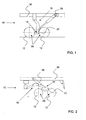
- Fig. 1 to 4 each show an embodiment of the rail driving device 10 according to the invention, wherein in each case the same reference numerals describe the same components.
- Two-way vehicles are used on private or public rail networks, for example, for track work, catenary assembly or other maintenance, repair and cleaning work, and in addition to their rubber tires for conventional roads on a rail vehicle 10 with rail wheels 12, which enable the vehicles to do so to move after extending the rail wheels 12 along the tracks of the rail network.
- the changeover to the rail operation takes place in that the rail wheels 12 are extended via actuators 28 in the form of hydraulic or pneumatic cylinders or by electrical actuation and the vehicle is thereby lifted over the rails, so that the road drive wheels are in the air.
- the actuators 28 are supported at one end usually on the subframe 30 of the vehicle.
- Fig. 1 shows a rail vehicle 10 with a bogie. This is preferably arranged on the front of the subframe 30 of a truck.
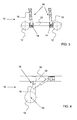
- Fig. 2 shows a Schienenfahr worn 10 with a bogie, which preferably rear is arranged on the subframe 30 of a truck.
- the rail driving device 10 comprises measuring devices 14 for the current detection of the load acting on each rail wheel 12.
- the measuring device 14 is arranged in the form of a load bolt on each side of a cross member 22 of the rail driving device 10, which receives the rail wheels 20 via an adapter and axles.
- the usually existing there support bolt was simply replaced by the load measuring pin.
- Each load measuring pin is connected via a measuring amplifier, not shown here, with a summation and evaluation module (also not shown here).
- Fig. 3 shows a Schienenfahr brought 10 with a Lore.
- a rail driving device comprises a closed frame 32.
- the measuring device 14 is arranged in the form of a load bolt on an only linearly displaceable pivot arm 18.
- the usually existing there support bolt was simply replaced by a load measuring pin.
- Fig. 4 finally shows a rail vehicle with a rocker.
- the measuring device 14 is arranged in the wheel bearing of the rail runner 12.
- FIG. 5 a flow chart of the method according to the invention for preventing tilting and / or derailment of a equipped with a rail vehicle 10 vehicle, especially a two-way vehicle, which is provided with at least one structure that can lead to a shift of the vehicle in operation, shown.
- load-dependent signals based on each individual rail wheel 12, 20 of the rail vehicle, are detected as actual values by means of the aforementioned measuring devices 14. These load signals are then transmitted to a summation and evaluation module 24, which is in communication with each measuring device 14, for determining a load torque. This module generates a shutdown signal when a predetermined load torque, which is set below the overturning moment, is achieved.
- This switch-off signal is transmitted to one or more control devices 26, in this case for controlling, for example, an aerial work platform HAB or the rail transport device SFE or other superstructures. This ensures the stability of the vehicle.
- the evaluation module 24 can also generate a shutdown signal when a predetermined minimum wheel load value is exceeded, so as to ensure the security against derailment.
- the controller 26 When concerns the shutdown signal only lastmomentredumpde measures are allowed via the controller 26. This means that, for example, the aerial work platform HAB can not be extended further.
- the maximum speed of the vehicle or of the rail driving device SFE is preferably reduced via the control device 26.
- the load measuring device 14 is a direct feedback on the effects of the individual movements of the structures with respect to the individual wheel loads and the load torque or tilting moment.
- the working diagrams in combination operation of structures, such as platform HAB and loading crane in, for example, so-called feeder operation dynamically changed.
- a reduced load on the loading crane causes an extension of the reach of the aerial work platform and vice versa.
Landscapes
- Engineering & Computer Science (AREA)
- Mechanical Engineering (AREA)
- Transportation (AREA)
- Vehicle Body Suspensions (AREA)
Applications Claiming Priority (2)
| Application Number | Priority Date | Filing Date | Title |
|---|---|---|---|
| DE102008004717 | 2008-01-16 | ||
| DE102008020401A DE102008020401A1 (de) | 2008-01-16 | 2008-04-24 | Schienenfahreinrichtung, Fahrzeug mit einer solchen Schienenfahreinrichtung sowie Verfahren zur Vermeidung des Kippens und/oder Entgleisens eines mit einer Schienenfahreinrichtung ausgerüsteteten Fahrzeugs |
Publications (1)
| Publication Number | Publication Date |
|---|---|
| EP2080646A2 true EP2080646A2 (fr) | 2009-07-22 |
Family
ID=40627203
Family Applications (1)
| Application Number | Title | Priority Date | Filing Date |
|---|---|---|---|
| EP20080018453 Withdrawn EP2080646A2 (fr) | 2008-01-16 | 2008-10-22 | Dispositif de transport sur rail, véhicule doté d'un tel dispositif de transport sur rail et procédé destiné à empêcher le basculement et/ou le déraillement d'un véhicule pourvu d'un dispositif de transport sur rail |
Country Status (1)
| Country | Link |
|---|---|
| EP (1) | EP2080646A2 (fr) |
Cited By (2)
| Publication number | Priority date | Publication date | Assignee | Title |
|---|---|---|---|---|
| ITPD20100200A1 (it) * | 2010-06-25 | 2011-12-26 | Colmar S P A | Dispositivo di sicurezza per macchine operatrici su rotaia |
| CN112356872A (zh) * | 2020-12-23 | 2021-02-12 | 中铁第四勘察设计院集团有限公司 | 一种高速磁浮车辆的应急轮结构 |
-
2008
- 2008-10-22 EP EP20080018453 patent/EP2080646A2/fr not_active Withdrawn
Cited By (2)
| Publication number | Priority date | Publication date | Assignee | Title |
|---|---|---|---|---|
| ITPD20100200A1 (it) * | 2010-06-25 | 2011-12-26 | Colmar S P A | Dispositivo di sicurezza per macchine operatrici su rotaia |
| CN112356872A (zh) * | 2020-12-23 | 2021-02-12 | 中铁第四勘察设计院集团有限公司 | 一种高速磁浮车辆的应急轮结构 |
Similar Documents
| Publication | Publication Date | Title |
|---|---|---|
| EP2289834B1 (fr) | Grue | |
| DE3017867C2 (fr) | ||
| DE102008023645A1 (de) | Omnidirektionales Fahrzeug-System und zugehörige Hubarbeitsbühne | |
| EP0675069B1 (fr) | Machine pour voie ferroviaire avec grue pivotante | |
| DE102010023069A1 (de) | Verfahren zum Bestimmen einer Kippwahrscheinlichkeit bei einem Flurförderzeug | |
| DE102007032056A1 (de) | Anhänger und Anhängerzug für Flurförderzeuge | |
| EP2781404A2 (fr) | Dispositif de surveillance de la sécurité d'état d'une semi-remorque basculante | |
| DE102009054293B4 (de) | Verfahren zum Lenken eines Nachläufers | |
| EP2733036B1 (fr) | Machine mobile comprenant une installation de chargement | |
| DE102008020401A1 (de) | Schienenfahreinrichtung, Fahrzeug mit einer solchen Schienenfahreinrichtung sowie Verfahren zur Vermeidung des Kippens und/oder Entgleisens eines mit einer Schienenfahreinrichtung ausgerüsteteten Fahrzeugs | |
| DE102004028053A1 (de) | Verfahren und Vorrichtung zur Kippvermeidung eines Flurförderzeugs | |
| EP2080646A2 (fr) | Dispositif de transport sur rail, véhicule doté d'un tel dispositif de transport sur rail et procédé destiné à empêcher le basculement et/ou le déraillement d'un véhicule pourvu d'un dispositif de transport sur rail | |
| DE4041970B4 (de) | Fahrgestell, insbesondere für einen Zweiwege-Bagger | |
| DE102016225045A1 (de) | Mobilkran | |
| DE202008005702U1 (de) | Schienenfahreinrichtung und Fahrzeug mit einer solchen Schienenfahreinrichtung | |
| DE102005020454B4 (de) | Verfahren und Vorrichtung zum Radsatzwechsel an Schienenfahrzeugen mittels einer verfahrbaren Einrichtung | |
| DE29521150U1 (de) | Wägevorrichtung für ein Fahrzeug | |
| DE102007034207A1 (de) | Rahmen zur Befestigung einer Anbauvorrichtung an einem Lastkraftwagen | |
| DE102021123505A1 (de) | Transportfahrzeug | |
| DE102014113668B4 (de) | Zweiwegefahrzeug und Verfahren zum Absenken oder Anheben eines Radträgers | |
| DE102004001727A1 (de) | Lenkeinrichtung für ein Fahrzeug | |
| DE2735385A1 (de) | Fahrbares portal | |
| EP0384105A1 (fr) | Dispositif de guidage sur voie pour véhicules sur pneumatiques | |
| DE19956785C1 (de) | Stützradanordnung | |
| DE10233874A1 (de) | Verfahren zum Steuern des Betriebs wenigstens einer längs einer Fahrbahn verfahrbaren Katze mit einem Fahrwerk und einem Hubwerk |
Legal Events
| Date | Code | Title | Description |
|---|---|---|---|
| PUAI | Public reference made under article 153(3) epc to a published international application that has entered the european phase |
Free format text: ORIGINAL CODE: 0009012 |
|
| AK | Designated contracting states |
Kind code of ref document: A2 Designated state(s): AT BE BG CH CY CZ DE DK EE ES FI FR GB GR HR HU IE IS IT LI LT LU LV MC MT NL NO PL PT RO SE SI SK TR |
|
| AX | Request for extension of the european patent |
Extension state: AL BA MK RS |
|
| 19U | Interruption of proceedings before grant |
Effective date: 20090827 |
|
| 19W | Proceedings resumed before grant after interruption of proceedings |
Effective date: 20100416 |
|
| RAP1 | Party data changed (applicant data changed or rights of an application transferred) |
Owner name: HILTON KOMMUNAL GMBH |
|
| STAA | Information on the status of an ep patent application or granted ep patent |
Free format text: STATUS: THE APPLICATION IS DEEMED TO BE WITHDRAWN |
|
| 18D | Application deemed to be withdrawn |
Effective date: 20110502 |