EP2080672B1 - Mobiltelefonhalter mit seitlichen Anschlüssen, insbesondere für ein Fahrzeug - Google Patents
Mobiltelefonhalter mit seitlichen Anschlüssen, insbesondere für ein Fahrzeug Download PDFInfo
- Publication number
- EP2080672B1 EP2080672B1 EP08460003A EP08460003A EP2080672B1 EP 2080672 B1 EP2080672 B1 EP 2080672B1 EP 08460003 A EP08460003 A EP 08460003A EP 08460003 A EP08460003 A EP 08460003A EP 2080672 B1 EP2080672 B1 EP 2080672B1
- Authority
- EP
- European Patent Office
- Prior art keywords
- holder
- slide
- mobile phone
- guide
- pin
- Prior art date
- Legal status (The legal status is an assumption and is not a legal conclusion. Google has not performed a legal analysis and makes no representation as to the accuracy of the status listed.)
- Not-in-force
Links
Images



Classifications
-
- B—PERFORMING OPERATIONS; TRANSPORTING
- B60—VEHICLES IN GENERAL
- B60R—VEHICLES, VEHICLE FITTINGS, OR VEHICLE PARTS, NOT OTHERWISE PROVIDED FOR
- B60R11/00—Arrangements for holding or mounting articles, not otherwise provided for
- B60R11/02—Arrangements for holding or mounting articles, not otherwise provided for for radio sets, television sets, telephones, or the like; Arrangement of controls thereof
- B60R11/0241—Arrangements for holding or mounting articles, not otherwise provided for for radio sets, television sets, telephones, or the like; Arrangement of controls thereof for telephones
-
- H—ELECTRICITY
- H04—ELECTRIC COMMUNICATION TECHNIQUE
- H04M—TELEPHONIC COMMUNICATION
- H04M1/00—Substation equipment, e.g. for use by subscribers
- H04M1/02—Constructional features of telephone sets
- H04M1/04—Supports for telephone transmitters or receivers
Definitions
- This invention relates to a mobile phone holder provided with a lateral power connection and, if applicable, with lateral signal connections, and used in mechanical vehicles.
- the holder is provided with a base, a cover and a slide, which is mounted slidably in the base and into which a mobile phone is insertable.
- the holder is further provided with an unlocking module with lateral buttons, which are connected to an eccentric wheel coupling the lateral buttons, and which, when pressed, unlock the mobile phone.
- PCT patent application WO 9811747 describes a mobile phone holder, which body is provided with a cavity in its lower part adapted to accommodate a mobile phone, whereas in the upper part of the body there is a spring-activated catch provided with a rotatably mounted locking bar, which is pressed by the mobile phone and, forced by the spring, catches the upper part of the phone pressing it down to the surface of the cavity in the holder.
- the most commonly used phone holders have power and signal connections in the lower part and the connection with a corresponding socket of a mobile phone is achieved automatically once the phone is inserted into the cavity of the holder where the connections are located.
- European patent application EP 1 112 893 A1 describes a mobile phone holder, which is provided not only with a signal connection in the lower part but also with an antenna plug, which is located in the upper part of the holder and enters the corresponding socket of the mobile phone while the phone is inserted into the holder.
- German utility model DE 201 06 566 U1 describes a mobile phone holder, which - in its lower part - is provided with a cavity locating the phone.
- the cavity has signal and power plug connectors and, in its upper part, a slide, which presses the mobile phone towards the cavity and protects it from falling out.
- To release the slide in order to remove the phone it is necessary to press the button on its front surface to release the lock.
- the slide may also be used to adjust the holder to the length of the mobile phone to be inserted.
- German utility model DE 297 05 230 U1 describes a mobile phone holder, in the lower part of which there is a cavity to locate the phone, while in the upper part of which there is a spring-activated catch to protect the phone from falling out.
- In the lower part of the holder there is an elastic antenna plug, which is directed perpendicularly to the bottom of the mobile phone and which enters into the antenna socket in the lower part of the mobile phone automatically when the phone is inserted into the holder.
- the catch in the upper part of the holder consists of many small parts and is released when the button, located in the middle part of the catch, is pressed.
- this design does not ensure firm mounting and increases the production costs of the holder.
- Generic German document DE 10 2006 005 111 A1 describes a mobile phone holder, which lower cavity is provided with a signal connection and a power connection and a phone is locked in the holder by means of a sliding element, located slideably in the casing comprising a base and a cover.
- the phone is mounted in the sliding element.
- the lower part of the sliding element is provided with a cavity to accommodate a mobile phone, whereas the upper part has an elastic catch, which mounts the mobile phone when it is inserted into the holder.
- the phone is locked in its "moved" position by means of an additional locking mechanism.
- the locking mechanism can be released by pressing a lateral button of an unlocking module in the holder.
- the holder is also provided with an electronic module, which enables cooperation with a hands-free kit installed in the mechanical vehicle.
- the object of this invention is to provide a mobile phone holder for mechanical vehicles, which enables an automatic connection between the power sockets and/or signal sockets on a lateral side of the phone and the corresponding plugs of the phone when it is inserted into the holder.
- a mobile phone holder for a vehicle which is characterized in that the slide of the holder is provided with a power plug, mounted slideably in it, the slide having a casing and a first and second pins, A first guide is provided in the base and guiding the first pin, and a second guide is provided in the cover and guiding the second pin.
- the first and second pins being inclined towards the longitudinal axis of the holder.
- the first pin being further guided along a third guide of a flat protrusion of the holder, the protrusion being perpendicular to the holder longitudinal axis, thus making the power plug move perpendicularly to the longitudinal axis of the holder.
- the casing of the power plug is also a casing of the signal plugs, which are adapted to engage with corresponding sockets on the lateral side of the mobile phone.
- the slide is preferably provided with an insert, which is mounted in the slide and slidably in the longitudinal direction of the holder.
- the insert has supports with a catch rotatably mounted thereto.
- the catch is provided with a spring and is adapted to holds the upper edge of a mobile phone.
- the catch is favourably provided with a blocking protrusions, which are adapted to engage with guides in the protrusion of the body of the unlocking module and to blocks the catch when the slide is in its lowest position.
- the protrusion of the body of the unlocking module is favourably preferably provided with a slot, in which a guide pin, mounted slideably in the hole of the plate of the slide, is guided perpendicularly to the surface of the plate and is adapted to releases the protrusion of the body of the unlocking module when the phone is inserted, thus allowing the motion of the slide to its lowest position.
- the unlocking module has advantageously a body, which expanded arms are also the guides for the slide.
- the cover is provided in its lateral part with a guide inclined to the axis of the holder analogously to the guide of the base and adapted to guide the pin of the power plug casing. adapted to guide the pin of the casing of the power plug.
- the slide is provided on its plate with an antenna plug.
- the performance tests of the mobile phone holder for mechanical vehicles proved that thanks to its design it allows mounting the mobile phones provided with power sockets and, if applicable, with signal sockets on the lateral side and the mobile phones provided with power sockets on the lateral side, signal sockets on the bottom side and an antenna socket on the rear side. It was also proved that the holder ensures a firm mounting and a correct connection between the phone and electronic or electric devices of the mechanical vehicle.
- Fig. 1 is a perspective view of the holder mounted within a mechanical vehicle
- Fig. 2 is a perspective view of the holder, according to the Fig. 1 , with a mobile phone in it, provided with power sockets on its left lateral side
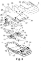
- Fig. 3 is an exploded view of the components of the holder, according to the Fig. 1
- Fig. 4 is a perspective view of the slide of the holder with a cover
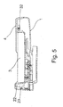
- Fig. 5 is an axial section of the holder, according to the Fig. 1 , along the A-A axis
- Fig. 1 is a perspective view of the holder mounted within a mechanical vehicle
- Fig. 2 is a perspective view of the holder, according to the Fig. 1 , with a mobile phone in it, provided with power sockets on its left lateral side
- Fig. 3 is an exploded view of the components of the holder, according to the Fig. 1
- Fig. 4 is a perspective view of the slide of the holder with
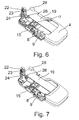
- FIG. 6 is a perspective view of an axial section of the holder, according to the Fig. 1 , with the cover and the slide removed;
- Fig. 7 is a perspective view of an axial section of the holder, according to the Fig. 1 , in a released position;
- Fig. 8 is a perspective view of the holder provided with an additional antenna plug located on the slide.
- the holder is designed for a mobile phone, in which the signal is transferred from the holder to a hands-free kit via a wireless connection (BLUETOOTH), especially to a mobile phone T provided with a power socket and, possibly, with a signal socket located on the lateral surface of the phone.
- the mobile phone holder according to the invention, consists of the following key components: a base 1 , a slide 3 , a module 2 unlocking the slide and a cover 4 ( Figs. 1 to 3 ).
- the base 1 of the holder consists of a lower plate 5 , which edges protrude upwards and which lower part is connected with a mounting element 6 to mount the holder on a rack within a mechanical vehicle.
- On the lower plate 5 there is an electronic module installed, not depicted in the drawing, which is adapted to provide a connection between the holder and electronic or electric devices within a vehicle.
- On one side of the base 1 there is provided a protrusion 7 , which is also the edge of the base 1 , with a guide 8 inclined to the A-A axis at an acute angle and adapted to guide the casing 39 of the power plug 9 and, if applicable, a signal plug, which is not depicted in the drawing.
- an unlocking button-type module 2 which is firmly mounted and which is located by the pins 10 in the base 1 .
- This module consists of a body 11 , which has a shape of two arms 12 , connected with a cross bar 13 provided with a protrusion 14 and two buttons 15 , which are mounted slideably and perpendicularly to the holder axis and which are provided with springs 16 , and which are connected to each other eccentrically by means of a wheel 17 .
- the arms 12 of the body 11 directed upwards, are the guides, along which the slide 3 moves.
- the buttons 15 are provided with teeth 18 , which are adapted to engage with the corresponding catches of the slide 3 , resulting in the slide being blocked when the catches are drawn aside. Move of the teeth towards the A-A axis of the holder, caused by pressing the buttons 15 , results in releasing the slide 3 and allowing its move in relation to the holder, upwards or downwards, along the arms 12 of the unlocking module 2 . Releasing the buttons 15 results in their return, pushed by the springs 16 , to the position of protruding from the holder.
- the slide 3 has a shape of a plate 19 , which is provided in its lower part with a cavity 20 , where the mobile phone can be placed, whereas in it upper part there is provided a protrusion 21 , inside which there is a catch 22 , mounted rotatably in an insert 36 located under the plate and having a form of a plate with supports.
- the rotatably mounted catch 22 is pressed down by means of a spring 23 to the upper edge of the mobile phone.
- the catch 22 is provided with lateral protrusions 24 , which are adapted to engage with guides 25 , located at the end of the protrusion 14 of the unlocking module 2 and designed to block the catch 22 in a position where the mobile phone T is locked.
- the insert 36 is additionally provided with a pin 26 , protruding from its centre, the pin is mounted slideably in a slot between the guides 25 of the protrusion 14 of the unlocking module 2 and then goes through the hole 27 of the slide.
- This pin prevents the slide from being moved when the pin is not pressed by a mobile phone.
- This blocking arrangements protects the power plug 9 from being broken in case of an attempt to insert a mobile phone into the holder when slide 3 is moved down.
- the plate 19 of the slide 3 is also provided with two protruding corners 28 , which locate the mobile phone in the slide.
- the casing 39 of the power plug 9 is made of a material providing electric insulation, favourably plastic, and both - the lower and the upper pin 34 are mounted slideably in two guides.
- the lower pin 34 is guided concurrently along the longitudinal guide 30 of the flat protrusion 29 , which is perpendicular to the A-A axis of the holder and along the first guide 8 of the base 1 , inclined at an acute angle to the A-A axis of the holder.
- the other pin 34 is guided along a guide in the protrusion 31 in the cover 4 , not depicted in the drawing and corresponding to and inclined at the same angle to the A-A axis as the guide 8 is.
- the shape of the lower part of the cover 4 of the holder is the same as the shape of the cavity 20 of the slide 3 , and at the inside of the cover 4 there are guides for the slide 3 , not depicted in the drawing.
- the mobile phone holder operates as follows:
- the slide 3 of the holder In a released position, as shown in the Fig. 1 and the Fig. 7 , the slide 3 of the holder is in its upper location.
- the phone pushes the pin 26 thus unblocking the holder.
- the catch 22 blocks the mobile phone in the slide 3 .
- the slide 3 with a mobile phone in it moves downwards, which results in that the guides 25 of the unlocking module 2 press the protrusions 24 of the catch 22 , which is blocked in the lower position, locking the mobile phone.
- the guides 8 and the guide 30 have an effect on the pin 34 of the casing 39 and make the power plug 9 protrude and enter the power socket on the lateral side of the mobile phone T .
- a mobile phone is provided with sockets both on the lateral and the bottom side, and the holder is provided with such plugs in the lower part of the base 1 , moving the phone in a slide 3 downwards results in that these plugs in the base 1 enter into the socket of the phone.
- the embodiment of the holder presented here enables safe mounting a mobile phone in it, without a risk of the lateral power plug 9 or, if applicable, other lateral signal plugs, being broken.
- the Fig. 8 shows other embodiment of the holder, according to the invention, where the holder is provided with an additional antenna plug 33 , mounted elastically in the plate 19 of the slide 3 . This plug automatically enters the corresponding antenna socket located on the rear side of a mobile phone.
Landscapes
- Engineering & Computer Science (AREA)
- Mechanical Engineering (AREA)
- Telephone Set Structure (AREA)
Claims (8)
- Mobiltelefonhalterung mit seitlichen Anschlüssen, insbesondere für Fahrzeuge; Halterung ausgerüstet mit einem Grundkörper (1), Deckel (4) und Schieber (3), der im Grundkörper (1) verschiebbar gelagert ist und in welchem das Mobiltelefon befestigt wird, wobei die Halterung auch mit einer Entriegelungsvorrichtung (2) mit seitlichen Tasten (15) ausgerüstet ist. Diese Tasten sind mit einem Exzenterrad (17) verbunden und entriegeln nach der Betätigung das Mobiltelefon, gekennzeichnet dadurch, dass der Schieber (3) über einen verschiebbar integrierten Versorgungsstecker (9) und ein Gehäuse (39) sowie die ersten und zweiten Zapfen (34) verfügt; im Grundkörper (1) befindet sich die erste Führung (8), die den ersten Zapfen führt und im Deckel (4) befindet sich die zweite Führung für den zweiten Zapfen, wobei die erste und die zweite Führung zur Längsachse des Halterung geneigt sind und der erste Zapfen auch in der dritten Führung (30) des flachen Vorsprungs (29) der Halterung geführt wird, wobei dieser flache Vorsprung zur Längsachse der Halterung senkrecht ist und den Versorgungsstecker (9) in eine zur Längsachse der Halterung senkrechte Richtung bewegt.
- Halterung nach Anspruch 1, gekennzeichnet dadurch, dass das Gehäuse (39) des Versorgungssteckers (9) zugleich ein Gehäuse für die Signalstecker bildet, welche zum Anschluss an die entsprechenden Buchsen der Seitenwand des Mobiltelefons vorgesehen sind.
- Halterung nach Anspruch 1, gekennzeichnet dadurch, dass der Schieber (3) mit einer Einlage (36) ausgerüstet ist, die im Schieber (3) in Längsrichtung der Halterung verschiebbar gelagert ist, wobei die Einlage (36) mit Stützelementen ausgerüstet ist, welche über einen drehbar gelagerten Haken (22) mit einer Feder (23) verfügen, der zur Befestigung der oberen Kante des Mobiltelefons vorgesehen ist.
- Halterung nach Anspruch 3, gekennzeichnet dadurch, dass der Haken (22) über Verriegelungsvorsprünge (24) verfügt, die zum Einhaken an Führungen (25) im Vorsprung (14) des Körpers (11) der Entriegelungsvorrichtung (2) und zur Verriegelung dieses Hakens (22) in der unteren Stellung des Schiebers (3) vorgesehen sind.
- Halterung nach Anspruch 4, gekennzeichnet dadurch, dass der Vorsprung (14) des Körpers (11) der Entriegelungsvorrichtung (2) über einen Schlitz (35) verfügt, in welchem der Führungszapfen (26) verschoben wird, der im Loch (27) der Platte (19) des Schiebers (3) senkrecht zur Oberfläche dieser Platte (19) verschiebbar gelagert ist und den Vorsprung (14) des Körpers (11) der Entriegelungsvorrichtung (2) nach Hineinpressen des Telefons entriegelt und die Verschiebung des Schiebers (3) in seine untere Stellung ermöglicht.
- Halterung nach Anspruch 1, gekennzeichnet dadurch, dass die Entriegelungsvorrichtung (2) über einen Körper (11) verfügt, dessen Arme (12) zugleich eine Führung für den Schieber (3) bilden.
- Halterung nach Anspruch 1, gekennzeichnet dadurch, dass ihr Deckel (4) in seinem seitlichen Teil über eine Führung (31) verfügt, die zur Halterungsachse geneigt ist - genauso, wie die Führung (8) zum Grundkörper (1) - und zur Führung des Zapfens (34) der Gehäuses (39) des Versorgungssteckers (9) vorgesehen ist.
- Halterung nach Anspruch 1 (3), gekennzeichnet dadurch, dass der Schieber (3) auf seiner Platte (19) mit einem Antennenstecker ausgerüstet ist (33).
Priority Applications (4)
| Application Number | Priority Date | Filing Date | Title |
|---|---|---|---|
| EP08460003A EP2080672B1 (de) | 2008-01-20 | 2008-01-20 | Mobiltelefonhalter mit seitlichen Anschlüssen, insbesondere für ein Fahrzeug |
| AU2008264204A AU2008264204A1 (en) | 2008-01-20 | 2008-12-24 | A mobile phone holder with lateral connections, especially for a mechanical vehicle |
| CA002648244A CA2648244A1 (en) | 2008-01-20 | 2008-12-29 | A mobile phone holder with lateral connections, especially for a mechanical vehicle |
| US12/348,289 US8078237B2 (en) | 2008-01-20 | 2009-01-03 | Mobile phone holder with lateral connections, especially for a mechanical vehicle |
Applications Claiming Priority (1)
| Application Number | Priority Date | Filing Date | Title |
|---|---|---|---|
| EP08460003A EP2080672B1 (de) | 2008-01-20 | 2008-01-20 | Mobiltelefonhalter mit seitlichen Anschlüssen, insbesondere für ein Fahrzeug |
Publications (2)
| Publication Number | Publication Date |
|---|---|
| EP2080672A1 EP2080672A1 (de) | 2009-07-22 |
| EP2080672B1 true EP2080672B1 (de) | 2012-10-03 |
Family
ID=39677695
Family Applications (1)
| Application Number | Title | Priority Date | Filing Date |
|---|---|---|---|
| EP08460003A Not-in-force EP2080672B1 (de) | 2008-01-20 | 2008-01-20 | Mobiltelefonhalter mit seitlichen Anschlüssen, insbesondere für ein Fahrzeug |
Country Status (4)
| Country | Link |
|---|---|
| US (1) | US8078237B2 (de) |
| EP (1) | EP2080672B1 (de) |
| AU (1) | AU2008264204A1 (de) |
| CA (1) | CA2648244A1 (de) |
Families Citing this family (16)
| Publication number | Priority date | Publication date | Assignee | Title |
|---|---|---|---|---|
| ATE482851T1 (de) * | 2008-08-06 | 2010-10-15 | Bury Sp Zoo | Mobiltelefonhalter für fahrzeuge |
| US20100315041A1 (en) * | 2009-06-15 | 2010-12-16 | Qing Song Tan | Portable phone holder and charger with quick release feature |
| US20100317412A1 (en) * | 2009-06-15 | 2010-12-16 | Qing Song Tan | Portable phone holder and charger |
| US8306579B2 (en) * | 2009-07-29 | 2012-11-06 | Motorola Solutions, Inc. | Vehicular adapter apparatus |
| KR101097520B1 (ko) * | 2009-09-01 | 2011-12-22 | 에코플라스틱 주식회사 | 핸드폰 거치대 및 이를 포함하는 자동차 |
| EP2325049B1 (de) * | 2009-11-23 | 2012-03-21 | BURY Sp. z o.o. | Mobiltelefonhalter mit seitlichen Anschlüssen |
| EP2391097B1 (de) * | 2010-05-24 | 2012-10-03 | BURY Sp. z o.o. | Mobiltelefonhalter |
| DE102011014978A1 (de) * | 2011-03-24 | 2012-09-27 | Continental Automotive Gmbh | Fahrzeugdatenaufzeichnungsvorrichtung |
| US9130384B2 (en) | 2011-10-06 | 2015-09-08 | Prong, Inc. | Smart phone and/or consumer electronics device charger system |
| WO2013102687A1 (es) * | 2012-01-03 | 2013-07-11 | Barba Carujo Enrique | Funda de teléfono móvil con medios de extraccion del mismo |
| JP2014207636A (ja) * | 2013-04-16 | 2014-10-30 | 富士通株式会社 | 卓上ホルダ |
| WO2015059508A1 (en) * | 2013-10-24 | 2015-04-30 | Teleplan Technology B.V. | Method and apparatus for testing cell phones |
| KR101500380B1 (ko) * | 2013-12-26 | 2015-03-09 | 현대자동차 주식회사 | 차량용 스마트폰 거치대 |
| US9866677B1 (en) | 2015-10-14 | 2018-01-09 | Michael K Maguire | Mobile device monitoring system |
| WO2018010016A1 (en) * | 2016-07-10 | 2018-01-18 | Block-Lock Inc. | Handheld unit control device for vehicles |
| CN109218489B (zh) * | 2018-09-29 | 2024-05-10 | 歌尔科技有限公司 | 一种夹紧装置及头戴设备 |
Family Cites Families (18)
| Publication number | Priority date | Publication date | Assignee | Title |
|---|---|---|---|---|
| DE29705230U1 (de) | 1996-05-15 | 1997-08-28 | Peiker, Andreas, Dipl.-Ing., 61381 Friedrichsdorf | Telefongerät mit einer Haltesicherung |
| DE59709641D1 (de) | 1996-09-13 | 2003-04-30 | Andreas Peiker | Grossraumreisefahrzeug mit einer nachrichtentechnischen verbindungseinrichtung sowie verbindungseinrichtung und teilnehmerstation |
| JP2908444B1 (ja) * | 1998-07-07 | 1999-06-21 | 静岡日本電気株式会社 | 携帯機器用ホルダ |
| US6019624A (en) * | 1998-07-29 | 2000-02-01 | Motorola, Inc. | Vehicular adapter insertion mechanism |
| DE29909215U1 (de) * | 1999-05-28 | 2000-10-05 | Peiker, Andreas, 61381 Friedrichsdorf | Halterung für Funktelefone |
| US20020009195A1 (en) * | 1999-10-26 | 2002-01-24 | Telefonaktiebolaget Lm Ericsson | Holder for mobile telephones |
| EP1112893A1 (de) | 2000-01-03 | 2001-07-04 | Cullmann GmbH | Mobiltelefon-Halterung mit Freisprecheinrichtung für ein Fahrzeug |
| US7062300B1 (en) * | 2000-11-09 | 2006-06-13 | Ki Il Kim | Cellular phone holder with charger mounted to vehicle dashboard |
| DE20106566U1 (de) | 2001-04-14 | 2001-07-19 | E-Lead Electronic Co., Ltd, Shengang, Changhua | Schalt- und Aufnahmeeinrichtung zur Verwendung mit Mobiltelefonen und Peripheriekommunikationsgeräten dafür |
| US20020191782A1 (en) * | 2001-04-30 | 2002-12-19 | Beger Larry J. | Cradle device for a cellular telephone |
| DE10131335A1 (de) * | 2001-06-28 | 2003-01-09 | Bisplinghoff Gisela | Adapter füt einen Telefonhalter einer Freisprecheinrichtung |
| US7162281B2 (en) * | 2002-02-22 | 2007-01-09 | Dong Joo Kim | Mobile phone holder |
| ATE294082T1 (de) * | 2003-01-23 | 2005-05-15 | Sony Ericsson Mobile Comm Ab | Halter für aufklappbares mobiltelefon |
| TWM270153U (en) * | 2004-09-10 | 2005-07-11 | Da-Shuo Jang | A universal holder for digital devices or electronic products used in car |
| DE102006005111B4 (de) | 2005-02-09 | 2008-09-04 | Bury Gmbh & Co. Kg | Telefonhalter für ein Mobiltelefon |
| DE202005013523U1 (de) * | 2005-08-26 | 2005-11-10 | Nokia Corp. | Mobilgeräte-Klemmhalterung mit gedämpftem Freigabemechanismus |
| DE102006012763B3 (de) * | 2006-03-17 | 2007-10-18 | Bury Gmbh & Co. Kg | Gerätehalter mit einem beweglichen Kontaktstecker |
| CA2631932C (en) * | 2007-05-22 | 2014-08-26 | Wilson Electronics, Inc. | Mobile device cradle having an integrated antenna or amplifier |
-
2008
- 2008-01-20 EP EP08460003A patent/EP2080672B1/de not_active Not-in-force
- 2008-12-24 AU AU2008264204A patent/AU2008264204A1/en not_active Abandoned
- 2008-12-29 CA CA002648244A patent/CA2648244A1/en not_active Abandoned
-
2009
- 2009-01-03 US US12/348,289 patent/US8078237B2/en not_active Expired - Fee Related
Also Published As
| Publication number | Publication date |
|---|---|
| EP2080672A1 (de) | 2009-07-22 |
| CA2648244A1 (en) | 2009-07-20 |
| US20090186666A1 (en) | 2009-07-23 |
| US8078237B2 (en) | 2011-12-13 |
| AU2008264204A1 (en) | 2009-08-06 |
Similar Documents
| Publication | Publication Date | Title |
|---|---|---|
| EP2080672A1 (de) | Mobiltelefonhalter mit seitlichen Anschlüssen, insbesondere für ein Fahrzeug | |
| EP2151353B1 (de) | Mobiltelefonhalter für Fahrzeuge | |
| EP1973313B1 (de) | Fahrzeughalterung für ein Mobiltelefon | |
| EP2026544B1 (de) | Halterung für ein Mobiltelefon für ein Fahrzeug | |
| CN110145527B (zh) | 一种自锁连接装置及具有该自锁连接装置的电子设备 | |
| EP1835706B1 (de) | Gerätehalter mit einem beweglichen Kontaktstecker | |
| EP2536594B1 (de) | Verbindungsvorrichtung für einen multifunktionellen kasten und fahrzeug damit | |
| US20120295667A1 (en) | Cradle for mobile phones | |
| WO1998028895A2 (en) | Holder for a telephone handset, and assembly of a holder and a telephone handset | |
| US8306579B2 (en) | Vehicular adapter apparatus | |
| WO2007143256A2 (en) | Locking mechanism for a communication device | |
| US8056813B2 (en) | Chip card holder | |
| KR200261161Y1 (ko) | 휴대폰용 핸드 프리 거치대 | |
| EP2159107B1 (de) | Mobiltelefonhalter mit seitlichem Stromanschluss, speziell für ein mechanisches Fahrzeug | |
| CN202713842U (zh) | 一种夹持装置及便携式电子设备套件 | |
| EP2325049B1 (de) | Mobiltelefonhalter mit seitlichen Anschlüssen | |
| US20240293734A1 (en) | Controller for portable electronic device | |
| EP2262118B1 (de) | Haltung für Mobiltelefon mit schrägem Sockel | |
| US8293394B2 (en) | Battery cover latching mechanism | |
| KR20160003976U (ko) | 잠금가능 소켓 | |
| CN215883515U (zh) | 盖板锁止结构和车辆 | |
| CN219626919U (zh) | 一种sim卡座及移动终端 | |
| US20100053916A1 (en) | Card holding mechanism | |
| EP2391097B1 (de) | Mobiltelefonhalter | |
| CN102316189B (zh) | 用于移动电话的支座 |
Legal Events
| Date | Code | Title | Description |
|---|---|---|---|
| PUAI | Public reference made under article 153(3) epc to a published international application that has entered the european phase |
Free format text: ORIGINAL CODE: 0009012 |
|
| AK | Designated contracting states |
Kind code of ref document: A1 Designated state(s): AT BE BG CH CY CZ DE DK EE ES FI FR GB GR HR HU IE IS IT LI LT LU LV MC MT NL NO PL PT RO SE SI SK TR |
|
| AX | Request for extension of the european patent |
Extension state: AL BA MK RS |
|
| 17P | Request for examination filed |
Effective date: 20090825 |
|
| AKX | Designation fees paid |
Designated state(s): AT BE BG CH CY CZ DE DK EE ES FI FR GB GR HR HU IE IS IT LI LT LU LV MC MT NL NO PL PT RO SE SI SK TR |
|
| GRAP | Despatch of communication of intention to grant a patent |
Free format text: ORIGINAL CODE: EPIDOSNIGR1 |
|
| GRAS | Grant fee paid |
Free format text: ORIGINAL CODE: EPIDOSNIGR3 |
|
| GRAA | (expected) grant |
Free format text: ORIGINAL CODE: 0009210 |
|
| AK | Designated contracting states |
Kind code of ref document: B1 Designated state(s): AT BE BG CH CY CZ DE DK EE ES FI FR GB GR HR HU IE IS IT LI LT LU LV MC MT NL NO PL PT RO SE SI SK TR |
|
| REG | Reference to a national code |
Ref country code: GB Ref legal event code: FG4D |
|
| REG | Reference to a national code |
Ref country code: AT Ref legal event code: REF Ref document number: 577815 Country of ref document: AT Kind code of ref document: T Effective date: 20121015 Ref country code: CH Ref legal event code: EP |
|
| REG | Reference to a national code |
Ref country code: IE Ref legal event code: FG4D |
|
| REG | Reference to a national code |
Ref country code: DE Ref legal event code: R096 Ref document number: 602008019123 Country of ref document: DE Effective date: 20121129 |
|
| REG | Reference to a national code |
Ref country code: AT Ref legal event code: MK05 Ref document number: 577815 Country of ref document: AT Kind code of ref document: T Effective date: 20121003 |
|
| PG25 | Lapsed in a contracting state [announced via postgrant information from national office to epo] |
Ref country code: SI Free format text: LAPSE BECAUSE OF FAILURE TO SUBMIT A TRANSLATION OF THE DESCRIPTION OR TO PAY THE FEE WITHIN THE PRESCRIBED TIME-LIMIT Effective date: 20121003 |
|
| REG | Reference to a national code |
Ref country code: NL Ref legal event code: VDEP Effective date: 20121003 |
|
| REG | Reference to a national code |
Ref country code: LT Ref legal event code: MG4D |
|
| PG25 | Lapsed in a contracting state [announced via postgrant information from national office to epo] |
Ref country code: NO Free format text: LAPSE BECAUSE OF FAILURE TO SUBMIT A TRANSLATION OF THE DESCRIPTION OR TO PAY THE FEE WITHIN THE PRESCRIBED TIME-LIMIT Effective date: 20130103 Ref country code: LT Free format text: LAPSE BECAUSE OF FAILURE TO SUBMIT A TRANSLATION OF THE DESCRIPTION OR TO PAY THE FEE WITHIN THE PRESCRIBED TIME-LIMIT Effective date: 20121003 Ref country code: NL Free format text: LAPSE BECAUSE OF FAILURE TO SUBMIT A TRANSLATION OF THE DESCRIPTION OR TO PAY THE FEE WITHIN THE PRESCRIBED TIME-LIMIT Effective date: 20121003 Ref country code: HR Free format text: LAPSE BECAUSE OF FAILURE TO SUBMIT A TRANSLATION OF THE DESCRIPTION OR TO PAY THE FEE WITHIN THE PRESCRIBED TIME-LIMIT Effective date: 20121003 Ref country code: SE Free format text: LAPSE BECAUSE OF FAILURE TO SUBMIT A TRANSLATION OF THE DESCRIPTION OR TO PAY THE FEE WITHIN THE PRESCRIBED TIME-LIMIT Effective date: 20121003 Ref country code: ES Free format text: LAPSE BECAUSE OF FAILURE TO SUBMIT A TRANSLATION OF THE DESCRIPTION OR TO PAY THE FEE WITHIN THE PRESCRIBED TIME-LIMIT Effective date: 20130114 Ref country code: IS Free format text: LAPSE BECAUSE OF FAILURE TO SUBMIT A TRANSLATION OF THE DESCRIPTION OR TO PAY THE FEE WITHIN THE PRESCRIBED TIME-LIMIT Effective date: 20130203 Ref country code: FI Free format text: LAPSE BECAUSE OF FAILURE TO SUBMIT A TRANSLATION OF THE DESCRIPTION OR TO PAY THE FEE WITHIN THE PRESCRIBED TIME-LIMIT Effective date: 20121003 |
|
| PG25 | Lapsed in a contracting state [announced via postgrant information from national office to epo] |
Ref country code: BE Free format text: LAPSE BECAUSE OF FAILURE TO SUBMIT A TRANSLATION OF THE DESCRIPTION OR TO PAY THE FEE WITHIN THE PRESCRIBED TIME-LIMIT Effective date: 20121003 Ref country code: PT Free format text: LAPSE BECAUSE OF FAILURE TO SUBMIT A TRANSLATION OF THE DESCRIPTION OR TO PAY THE FEE WITHIN THE PRESCRIBED TIME-LIMIT Effective date: 20130204 Ref country code: LV Free format text: LAPSE BECAUSE OF FAILURE TO SUBMIT A TRANSLATION OF THE DESCRIPTION OR TO PAY THE FEE WITHIN THE PRESCRIBED TIME-LIMIT Effective date: 20121003 Ref country code: GR Free format text: LAPSE BECAUSE OF FAILURE TO SUBMIT A TRANSLATION OF THE DESCRIPTION OR TO PAY THE FEE WITHIN THE PRESCRIBED TIME-LIMIT Effective date: 20130104 Ref country code: PL Free format text: LAPSE BECAUSE OF FAILURE TO SUBMIT A TRANSLATION OF THE DESCRIPTION OR TO PAY THE FEE WITHIN THE PRESCRIBED TIME-LIMIT Effective date: 20121003 Ref country code: CY Free format text: LAPSE BECAUSE OF FAILURE TO SUBMIT A TRANSLATION OF THE DESCRIPTION OR TO PAY THE FEE WITHIN THE PRESCRIBED TIME-LIMIT Effective date: 20121003 |
|
| PG25 | Lapsed in a contracting state [announced via postgrant information from national office to epo] |
Ref country code: AT Free format text: LAPSE BECAUSE OF FAILURE TO SUBMIT A TRANSLATION OF THE DESCRIPTION OR TO PAY THE FEE WITHIN THE PRESCRIBED TIME-LIMIT Effective date: 20121003 |
|
| PG25 | Lapsed in a contracting state [announced via postgrant information from national office to epo] |
Ref country code: EE Free format text: LAPSE BECAUSE OF FAILURE TO SUBMIT A TRANSLATION OF THE DESCRIPTION OR TO PAY THE FEE WITHIN THE PRESCRIBED TIME-LIMIT Effective date: 20121003 Ref country code: CZ Free format text: LAPSE BECAUSE OF FAILURE TO SUBMIT A TRANSLATION OF THE DESCRIPTION OR TO PAY THE FEE WITHIN THE PRESCRIBED TIME-LIMIT Effective date: 20121003 Ref country code: DK Free format text: LAPSE BECAUSE OF FAILURE TO SUBMIT A TRANSLATION OF THE DESCRIPTION OR TO PAY THE FEE WITHIN THE PRESCRIBED TIME-LIMIT Effective date: 20121003 Ref country code: BG Free format text: LAPSE BECAUSE OF FAILURE TO SUBMIT A TRANSLATION OF THE DESCRIPTION OR TO PAY THE FEE WITHIN THE PRESCRIBED TIME-LIMIT Effective date: 20130103 Ref country code: SK Free format text: LAPSE BECAUSE OF FAILURE TO SUBMIT A TRANSLATION OF THE DESCRIPTION OR TO PAY THE FEE WITHIN THE PRESCRIBED TIME-LIMIT Effective date: 20121003 |
|
| PLBE | No opposition filed within time limit |
Free format text: ORIGINAL CODE: 0009261 |
|
| STAA | Information on the status of an ep patent application or granted ep patent |
Free format text: STATUS: NO OPPOSITION FILED WITHIN TIME LIMIT |
|
| PG25 | Lapsed in a contracting state [announced via postgrant information from national office to epo] |
Ref country code: MC Free format text: LAPSE BECAUSE OF NON-PAYMENT OF DUE FEES Effective date: 20130131 Ref country code: IT Free format text: LAPSE BECAUSE OF FAILURE TO SUBMIT A TRANSLATION OF THE DESCRIPTION OR TO PAY THE FEE WITHIN THE PRESCRIBED TIME-LIMIT Effective date: 20121003 Ref country code: RO Free format text: LAPSE BECAUSE OF FAILURE TO SUBMIT A TRANSLATION OF THE DESCRIPTION OR TO PAY THE FEE WITHIN THE PRESCRIBED TIME-LIMIT Effective date: 20121003 |
|
| REG | Reference to a national code |
Ref country code: CH Ref legal event code: PL |
|
| 26N | No opposition filed |
Effective date: 20130704 |
|
| REG | Reference to a national code |
Ref country code: IE Ref legal event code: MM4A |
|
| REG | Reference to a national code |
Ref country code: FR Ref legal event code: ST Effective date: 20130930 |
|
| PG25 | Lapsed in a contracting state [announced via postgrant information from national office to epo] |
Ref country code: CH Free format text: LAPSE BECAUSE OF NON-PAYMENT OF DUE FEES Effective date: 20130131 Ref country code: LI Free format text: LAPSE BECAUSE OF NON-PAYMENT OF DUE FEES Effective date: 20130131 |
|
| REG | Reference to a national code |
Ref country code: DE Ref legal event code: R097 Ref document number: 602008019123 Country of ref document: DE Effective date: 20130704 |
|
| PG25 | Lapsed in a contracting state [announced via postgrant information from national office to epo] |
Ref country code: FR Free format text: LAPSE BECAUSE OF NON-PAYMENT OF DUE FEES Effective date: 20130131 |
|
| PG25 | Lapsed in a contracting state [announced via postgrant information from national office to epo] |
Ref country code: IE Free format text: LAPSE BECAUSE OF NON-PAYMENT OF DUE FEES Effective date: 20130120 |
|
| PG25 | Lapsed in a contracting state [announced via postgrant information from national office to epo] |
Ref country code: MT Free format text: LAPSE BECAUSE OF FAILURE TO SUBMIT A TRANSLATION OF THE DESCRIPTION OR TO PAY THE FEE WITHIN THE PRESCRIBED TIME-LIMIT Effective date: 20121003 |
|
| PG25 | Lapsed in a contracting state [announced via postgrant information from national office to epo] |
Ref country code: TR Free format text: LAPSE BECAUSE OF FAILURE TO SUBMIT A TRANSLATION OF THE DESCRIPTION OR TO PAY THE FEE WITHIN THE PRESCRIBED TIME-LIMIT Effective date: 20121003 |
|
| PG25 | Lapsed in a contracting state [announced via postgrant information from national office to epo] |
Ref country code: LU Free format text: LAPSE BECAUSE OF NON-PAYMENT OF DUE FEES Effective date: 20130120 Ref country code: HU Free format text: LAPSE BECAUSE OF FAILURE TO SUBMIT A TRANSLATION OF THE DESCRIPTION OR TO PAY THE FEE WITHIN THE PRESCRIBED TIME-LIMIT; INVALID AB INITIO Effective date: 20080120 |
|
| REG | Reference to a national code |
Ref country code: DE Ref legal event code: R082 Ref document number: 602008019123 Country of ref document: DE Representative=s name: GRAMM, LINS & PARTNER PATENT- UND RECHTSANWAEL, DE |
|
| PGFP | Annual fee paid to national office [announced via postgrant information from national office to epo] |
Ref country code: GB Payment date: 20181121 Year of fee payment: 12 |
|
| PGFP | Annual fee paid to national office [announced via postgrant information from national office to epo] |
Ref country code: DE Payment date: 20190206 Year of fee payment: 12 |
|
| REG | Reference to a national code |
Ref country code: DE Ref legal event code: R119 Ref document number: 602008019123 Country of ref document: DE |
|
| GBPC | Gb: european patent ceased through non-payment of renewal fee |
Effective date: 20200120 |
|
| PG25 | Lapsed in a contracting state [announced via postgrant information from national office to epo] |
Ref country code: GB Free format text: LAPSE BECAUSE OF NON-PAYMENT OF DUE FEES Effective date: 20200120 Ref country code: DE Free format text: LAPSE BECAUSE OF NON-PAYMENT OF DUE FEES Effective date: 20200801 |