EP2080700B1 - Pylône et configuration de montage de moteur - Google Patents
Pylône et configuration de montage de moteur Download PDFInfo
- Publication number
- EP2080700B1 EP2080700B1 EP08253736.6A EP08253736A EP2080700B1 EP 2080700 B1 EP2080700 B1 EP 2080700B1 EP 08253736 A EP08253736 A EP 08253736A EP 2080700 B1 EP2080700 B1 EP 2080700B1
- Authority
- EP
- European Patent Office
- Prior art keywords
- engine
- mount
- pylon
- aft
- mounting arrangement
- Prior art date
- Legal status (The legal status is an assumption and is not a legal conclusion. Google has not performed a legal analysis and makes no representation as to the accuracy of the status listed.)
- Active
Links
Images


Classifications
-
- B—PERFORMING OPERATIONS; TRANSPORTING
- B64—AIRCRAFT; AVIATION; COSMONAUTICS
- B64D—EQUIPMENT FOR FITTING IN OR TO AIRCRAFT; FLIGHT SUITS; PARACHUTES; ARRANGEMENT OR MOUNTING OF POWER PLANTS OR PROPULSION TRANSMISSIONS IN AIRCRAFT
- B64D27/00—Arrangement or mounting of power plants in aircraft; Aircraft characterised by the type or position of power plants
- B64D27/40—Arrangements for mounting power plants in aircraft
- B64D27/404—Suspension arrangements specially adapted for supporting vertical loads
-
- B—PERFORMING OPERATIONS; TRANSPORTING
- B64—AIRCRAFT; AVIATION; COSMONAUTICS
- B64D—EQUIPMENT FOR FITTING IN OR TO AIRCRAFT; FLIGHT SUITS; PARACHUTES; ARRANGEMENT OR MOUNTING OF POWER PLANTS OR PROPULSION TRANSMISSIONS IN AIRCRAFT
- B64D27/00—Arrangement or mounting of power plants in aircraft; Aircraft characterised by the type or position of power plants
- B64D27/40—Arrangements for mounting power plants in aircraft
- B64D27/406—Suspension arrangements specially adapted for supporting thrust loads, e.g. thrust links
-
- Y—GENERAL TAGGING OF NEW TECHNOLOGICAL DEVELOPMENTS; GENERAL TAGGING OF CROSS-SECTIONAL TECHNOLOGIES SPANNING OVER SEVERAL SECTIONS OF THE IPC; TECHNICAL SUBJECTS COVERED BY FORMER USPC CROSS-REFERENCE ART COLLECTIONS [XRACs] AND DIGESTS
- Y02—TECHNOLOGIES OR APPLICATIONS FOR MITIGATION OR ADAPTATION AGAINST CLIMATE CHANGE
- Y02T—CLIMATE CHANGE MITIGATION TECHNOLOGIES RELATED TO TRANSPORTATION
- Y02T50/00—Aeronautics or air transport
- Y02T50/40—Weight reduction
Definitions
- This disclosure relates to a mounting arrangement for a gas turbine engine and, more particularly, to a mounting arrangement that includes front and rear engine mount beams that are integrally formed with respective pylon mount structures.
- a pylon pyramid includes a first or fore pylon mounting flange that is secured to a mating flange on a front engine mount beam at a first bolted joint. The front engine mount beam is then attached to the engine case via another bolted joint to provide a fore or front engine mount.
- An aft pylon flange includes a second pylon mounting flange that is secured to a mating flange on a rear engine mount beam at a second bolted joint.
- the rear engine mount beam is then attached to the engine case to provide a rear or aft engine mount.
- the invention provides a mounting arrangement for a gas turbine engine as claimed in claim 1.
- Figure 1 illustrates selected portions of an example turbine engine 10, such as a gas turbine engine 10 used for propulsion.
- the turbine engine 10 is circumferentially disposed about an engine centerline 12.
- the turbine engine 10 includes a fan 14, a compressor section 16, a combustion section 18, and a turbine section 20.
- the compressor section 16 and the turbine section 20 include corresponding blades 22 and vanes 24.
- air compressed in the compressor section 16 is mixed with fuel and burned in the combustion section 18 to produce hot gasses that are expanded in the turbine section 20.
- An engine case 26 is made up of case sections that are attached to each other to enclose the internal components of the turbine engine.
- Figure 1 is a somewhat schematic presentation for illustrative purposes only and is not a limitation on the disclosed examples. Additionally, there are various types of gas turbine engines, many of which could benefit from the examples disclosed herein and are not limited to the designs shown.
- a gas turbine engine may contain a gearbox disposed between the turbine section 20 and the fan 14, allowing the fan 14 to turn at a different speed than the turbine.
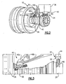
- FIG 2 illustrates a perspective view of the turbine engine 10 with a mounting arrangement 30.
- the mounting arrangement 30 includes a front mount 32 and a rear mount 34 that are used to mount the turbine engine 10 to a pylon 36, indicated schematically in Figure 2 .
- the pylon 36 is supported by a wing of an aircraft (not shown) as known.
- the front 32 and rear mounts 34 are used to attach the engine case 26 to the pylon 36
- the mounting arrangement 30 includes a pylon mount structure that comprises a fore portion 40 and an aft portion 42.
- the fore portion 40 comprises a pyramid structure that has a convergent portion 40a and a divergent portion 40b; however, other structural configurations could also be used.
- the divergent portion 40b comprises a plurality of discrete legs that extend from the convergent portion 40a toward the pylon 36.
- the aft portion 42 comprises a pylon mounting flange body 44 that extends downwardly from the pylon 36 toward the engine case 26.
- the mounting flange body 44 is positioned generally aft of the divergent portion 40b of the fore portion 40 of the pylon mount structure.
- the fore portion 40 and aft portions 42 are separate components.
- a fore engine mount beam 50 is integrally formed with the fore portion 40 of the pylon mount structure.
- the fore portion 40 and the fore engine mount beam 50 comprise a single-piece component, i.e. are a unitary component with a continuous and uninterrupted surface.
- An aft engine mount beam 52 is integrally formed with the aft portion 42 of the pylon mount structure.
- the aft portion 42 and the aft engine mount beam 52 also comprise a single piece component, i.e. are a unitary component with a continuous and uninterrupted surface.
- the fore engine mount beam 50 is unitarily formed with the convergent portion 40a of the pyramid structure.
- the fore engine mount beam 50 is then mounted to the engine case 26 to provide the front mount 32.
- the aft engine mount beam 52 is mounted to the engine case 26 at a rearward position to provide the rear mount 34. This configuration eliminates at least two bolted joint interfaces, which is advantageous from a cost and labor perspective.
- the fore engine mount beam 50 includes a first attachment structure portion 60 that supports a thrust link 62 and includes a second attachment structure portion 64 that provide an attachment interface to the engine case 26.
- the thrust link 62 includes a first link end 66 that is pivotally connected to one portion of the engine case 26 and a second link end 68 is connected to the first attachment structure portion 60 via a "whiffle" tree connector 70.
- the second link end 68 is supported by at least one mounting boss that is formed as one-piece with the fore engine mount beam 50.
- the second attachment structure portion 64 is associated with an engine mounting flange 72 and is attached to another portion of the engine case 26 at a bolted joint interface 74.
- FIG. 5 shows the rear mount 34 in greater detail.
- the aft engine mount beam 52 includes attachment structure 76 that is used to pivotally connect the aft engine mount beam 52 to another portion of the engine case 26 via a linkage assembly 78.
- the linkage assembly 78 includes at least one link member, and in the example shown, the linkage assembly 78 includes a first link 80 and a second link 82.
- the attachment structure 76 comprises a plurality of mounting lug portions that support pivot pins 84 for the linkage assembly.
- the links 80, 82 each have at least one pivotal connection to the aft engine mount beam 52 and at least one pivotal connection to the engine case 26.
- the engine case 26 includes lugs 86 that are formed to receive pivot pins 88.
Landscapes
- Engineering & Computer Science (AREA)
- Aviation & Aerospace Engineering (AREA)
- Structures Of Non-Positive Displacement Pumps (AREA)
- Vibration Prevention Devices (AREA)
- Turbine Rotor Nozzle Sealing (AREA)
Claims (11)
- Aménagement de montage (30) pour un moteur à turbine à gaz (10), comprenant :une structure de montage de pylône ayant une première partie de montage (40) et une seconde partie de montage (42) positionnée à l'arrière de ladite première partie de montage (40), lesdites première et seconde parties de montage étant destinées à être fixées à un pylône (36) ;une première poutrelle de montage de moteur (50) intégralement formée avec ladite première partie de montage (40) sous la forme d'un composant d'un seul tenant, ladite première poutrelle de montage de moteur (50) pouvant être fixée à une structure de carter de moteur (26) au niveau d'une interface de fixation avant (74) ; etune seconde poutrelle de montage de moteur (52) intégralement formée avec ladite seconde partie de montage (42) sous la forme d'un composant d'un seul tenant, ladite seconde poutrelle de montage de moteur (52) pouvant être fixée à la structure de carter de moteur (26) au niveau d'une interface de fixation arrière (76) ;dans lequel ladite première partie de montage (40) comprend une structure pyramidale ayant une partie convergente (40a) avec une partie divergente (40b) qui s'étend vers l'extérieur en s'écartant de ladite partie convergente (40a), ladite partie divergente (40b) étant censée être fixée au pylône (36), dans lequel ladite première poutrelle de montage de moteur (50) est intégralement formée avec ladite partie convergente (40a), et dans lequel ladite seconde partie de montage (42) comprend au moins une bride de montage de pylône (44) qui est positionnée à l'arrière de ladite partie divergente (40b) ;caractérisé en ce que ladite partie divergente (40b) comprend une pluralité de jambes qui s'étendent de ladite partie convergente (40a) vers le pylône (36).
- Aménagement de montage selon la revendication 1, dans lequel ladite première poutrelle de montage de moteur (50) peut être directement fixée à une structure de carter de moteur avant conjuguée (26) .
- Aménagement de montage selon la revendication 1 ou la revendication 2, dans lequel ladite seconde poutrelle de montage de moteur (52) peut être directement fixée à une structure de carter de moteur arrière conjuguée (26).
- Aménagement de montage selon la revendication 3, dans lequel ladite seconde poutrelle de montage de moteur (52) comprend au moins une monture pivot susceptible d'être fixée à la structure de carter de moteur arrière conjuguée (26).
- Aménagement de montage selon l'une quelconque des revendications précédentes, dans lequel ladite première poutrelle de montage de moteur (50) comprend une structure de fixation pour supporter au moins une bielle de poussée (62) et dans lequel ladite seconde poutrelle de montage de moteur (52) comprend une structure de fixation pour supporter à pivotement un ensemble de bielles (78).
- Aménagement de montage selon la revendication 1, comprenant en outre :un carter de moteur (26) ; dans lequel :ladite première poutrelle de montage de moteur (50) comprend une structure de fixation avant qui est fixée audit carter de moteur (26) pour former ladite interface de fixation avant (74), etladite seconde poutrelle de montage de moteur (52) comprend une structure de fixation arrière qui est fixée audit carter de moteur pour former ladite interface de fixation arrière (76).
- Aménagement de montage selon la revendication 6, dans lequel ladite structure de fixation avant comprend au moins un bossage de montage qui est formé d'une pièce avec ladite première poutrelle de montage de moteur (50) et comprenant au moins une bielle de poussée (62) ayant une première extrémité de bielle (66) raccordée à pivotement audit carter de moteur (26) et une seconde extrémité de bielle (68) qui est supportée par ledit au moins un bossage de montage.
- Aménagement de montage selon la revendication 6 ou la revendication 7, dans lequel ledit carter de moteur (26) comprend un premier ressaut (86) qui est formé d'une seule pièce avec ledit carter de moteur (26) et dans lequel ladite structure de fixation arrière (76) comprend un deuxième ressaut de montage qui est formé d'une seule pièce avec ladite seconde poutrelle de montage de moteur (52), et comprenant un ensemble de bielles pivotantes (78) ayant un premier élément de bielle (80) avec une première extrémité raccordée à pivotement audit premier ressaut (86) et une seconde extrémité raccordée à pivotement audit deuxième ressaut.
- Aménagement de montage selon la revendication 8, dans lequel ledit au moins un élément de bielle comprend un second élément de bielle (82) ayant une extrémité raccordée à pivotement à un troisième ressaut (86) formé d'une seule pièce avec ledit carter de moteur (26) et une extrémité opposée raccordée à pivotement à un quatrième ressaut formé d'une seule pièce avec ladite seconde poutrelle de montage de moteur (52).
- Aménagement de montage selon la revendication 6, dans lequel ladite partie de montage arrière (42) comprend au moins un bride de montage de pylône (44) qui est positionnée à l'arrière de ladite portion divergente (40b) et s'étend vers le bas depuis le pylône (36) vers ledit carter de moteur (26).
- Aménagement de montage selon l'une quelconque des revendications 6 à 10, dans lequel lesdits premier et second composants d'un seul tenant sont directement raccordés audit carter de moteur (26).
Applications Claiming Priority (1)
| Application Number | Priority Date | Filing Date | Title |
|---|---|---|---|
| US12/016,234 US8950702B2 (en) | 2008-01-18 | 2008-01-18 | Pylon and engine mount configuration |
Publications (3)
| Publication Number | Publication Date |
|---|---|
| EP2080700A2 EP2080700A2 (fr) | 2009-07-22 |
| EP2080700A3 EP2080700A3 (fr) | 2012-11-21 |
| EP2080700B1 true EP2080700B1 (fr) | 2014-02-26 |
Family
ID=40551082
Family Applications (1)
| Application Number | Title | Priority Date | Filing Date |
|---|---|---|---|
| EP08253736.6A Active EP2080700B1 (fr) | 2008-01-18 | 2008-11-14 | Pylône et configuration de montage de moteur |
Country Status (2)
| Country | Link |
|---|---|
| US (1) | US8950702B2 (fr) |
| EP (1) | EP2080700B1 (fr) |
Families Citing this family (19)
| Publication number | Priority date | Publication date | Assignee | Title |
|---|---|---|---|---|
| FR2924684B1 (fr) * | 2007-12-07 | 2010-01-01 | Snecma | Suspension d'un turboreacteur a un aeronef |
| US8561501B2 (en) * | 2011-05-31 | 2013-10-22 | United Technologies Corporation | Gearbox mount bracket |
| US9217337B2 (en) | 2012-05-10 | 2015-12-22 | United Technologies Corporation | Adjustable engine mount |
| US8985509B2 (en) * | 2012-08-31 | 2015-03-24 | United Technologies Corporation | Assembly for mounting a turbine engine to a pylon |
| US9297314B2 (en) * | 2012-12-19 | 2016-03-29 | United Technologies Corporation | Gas turbine engine with accessory gear box |
| WO2014189588A2 (fr) * | 2013-03-15 | 2014-11-27 | United Technologies Corporation | Bâti moteur comprenant un assemblage à oreilles à sûreté intégrée en attente, à facteur d'amplification dynamique réduit |
| US9863324B2 (en) * | 2013-03-21 | 2018-01-09 | United Technologies Corporation | Oil tank mount with stiffeners |
| JP6266775B2 (ja) | 2013-07-26 | 2018-01-24 | エムアールエイ・システムズ・エルエルシー | 航空機エンジンパイロン |
| FR3010700B1 (fr) * | 2013-09-18 | 2017-11-03 | Snecma | Dispositif de suspension d'un carter, turbomachine et ensemble propulsif |
| EP3049657B1 (fr) * | 2013-09-27 | 2018-10-03 | United Technologies Corporation | Systèmes de montage pour moteurs à turbine à gaz |
| FR3027873B1 (fr) * | 2014-11-03 | 2016-12-23 | Airbus Operations Sas | Attache moteur avant pour un moteur d'aeronef |
| EP3048271B1 (fr) * | 2014-12-10 | 2020-05-27 | Rolls-Royce Corporation | Nervure de renfort |
| JP6564455B2 (ja) * | 2015-05-08 | 2019-08-21 | 川崎重工業株式会社 | アクセサリギアボックスのマウント機構 |
| WO2018031548A1 (fr) | 2016-08-08 | 2018-02-15 | Lord Corporation | Systèmes, dispositifs et procédés de montage pour moteurs d'aéronef |
| FR3061149B1 (fr) * | 2016-12-27 | 2023-11-03 | Airbus Operations Sas | Structure primaire d'un mat pour groupe propulseur d'aeronef comportant une partie pyramidale a montants convergents |
| US11479104B2 (en) | 2019-07-24 | 2022-10-25 | Honeywell International Inc. | System and method for gas turbine engine mount with seal |
| US11970279B2 (en) | 2020-02-21 | 2024-04-30 | General Electric Company | Control system and methods of controlling an engine-mounting link system |
| US11939070B2 (en) | 2020-02-21 | 2024-03-26 | General Electric Company | Engine-mounting links that have an adjustable inclination angle |
| US11859506B2 (en) * | 2022-05-17 | 2024-01-02 | Pratt & Whitney Canada Corp. | Mounting structure for a gas turbine engine case |
Family Cites Families (20)
| Publication number | Priority date | Publication date | Assignee | Title |
|---|---|---|---|---|
| GB1516980A (en) * | 1974-12-24 | 1978-07-05 | Rolls Royce | Mounting ducted fan gas turbine engines on aircraft |
| GB1521847A (en) | 1976-04-30 | 1978-08-16 | Rolls Royce | Attachment for attaching jet propulsion engines to vehicle structure |
| US4428189A (en) | 1980-04-02 | 1984-01-31 | United Technologies Corporation | Case deflection control in aircraft gas turbine engines |
| US4934140A (en) | 1988-05-13 | 1990-06-19 | United Technologies Corporation | Modular gas turbine engine |
| GB9125011D0 (en) | 1991-11-25 | 1992-01-22 | Rolls Royce Plc | A mounting arrangement for a gas turbine engine |
| US5320307A (en) | 1992-03-25 | 1994-06-14 | General Electric Company | Aircraft engine thrust mount |
| US5443230A (en) | 1993-12-21 | 1995-08-22 | United Technologies Corporation | Aircraft wing/nacelle combination |
| WO1996020111A1 (fr) | 1994-12-23 | 1996-07-04 | United Technologies Corporation | Ensemble de montage pour turbine a gaz |
| GB2303884B (en) | 1995-04-13 | 1999-07-14 | Rolls Royce Plc | A mounting for coupling a turbofan gas turbine engine to an aircraft structure |
| US6126110A (en) * | 1997-12-22 | 2000-10-03 | Mcdonnell Douglas Corporation | Horizontally opposed trunnion forward engine mount system supported beneath a wing pylon |
| GB9927425D0 (en) | 1999-11-20 | 2000-01-19 | Rolls Royce Plc | A gas turbine engine mounting arrangement |
| US6296203B1 (en) * | 2000-05-24 | 2001-10-02 | General Electric Company | Snubber thrust mount |
| FR2820402B1 (fr) * | 2001-02-08 | 2003-05-02 | Eads Airbus Sa | Dispositif d'accrochage d'un moteur sur un aeronef |
| GB2375513B (en) | 2001-05-19 | 2005-03-23 | Rolls Royce Plc | A mounting arrangement for a gas turbine engine |
| FR2855494B1 (fr) * | 2003-05-27 | 2006-09-22 | Snecma Moteurs | Dispositif d'accrocharge arriere de moteur d'avion |
| FR2855495B1 (fr) * | 2003-05-27 | 2006-11-24 | Snecma Moteurs | Dispositif d'accrochage avant de moteur d'avion |
| FR2867158B1 (fr) * | 2004-03-04 | 2007-06-08 | Airbus France | Systeme de montage interpose entre un moteur d'aeronef et une structure rigide d'un mat d'accrochage fixe sous une voilure de cet aeronef. |
| FR2867155B1 (fr) | 2004-03-08 | 2007-06-29 | Snecma Moteurs | Suspension d'un moteur a la structure d'un avion |
| US7104306B2 (en) * | 2004-06-14 | 2006-09-12 | The Boeing Company | Cast unitized primary truss structure and method |
| GB0507721D0 (en) | 2005-04-16 | 2005-05-25 | Rolls Royce Plc | Gas turbine engine mounting arrangement |
-
2008
- 2008-01-18 US US12/016,234 patent/US8950702B2/en not_active Expired - Fee Related
- 2008-11-14 EP EP08253736.6A patent/EP2080700B1/fr active Active
Also Published As
| Publication number | Publication date |
|---|---|
| EP2080700A3 (fr) | 2012-11-21 |
| US20090184197A1 (en) | 2009-07-23 |
| EP2080700A2 (fr) | 2009-07-22 |
| US8950702B2 (en) | 2015-02-10 |
Similar Documents
| Publication | Publication Date | Title |
|---|---|---|
| EP2080700B1 (fr) | Pylône et configuration de montage de moteur | |
| RU2433070C2 (ru) | Силовая установка летательного аппарата, содержащая соединительный аэродинамический обтекатель, смонтированный на двух отдельных элементах | |
| US7007890B2 (en) | Turbojet designed to be fixed onto the AFT part of the fuselage of an aircraft, in upper position | |
| US8042342B2 (en) | Engine assembly for aircraft comprising an engine as well as a device for locking said engine | |
| CA2657397C (fr) | Moteur d'aeronef comprenant un berceau soutenant le carter de la soufflante, monte sur deux elements distincts | |
| US8727269B2 (en) | System and method for mounting an aircraft engine | |
| EP2441673B1 (fr) | Structure de support | |
| EP2080879B1 (fr) | Système de montage pour turbine à gaz | |
| CN103303484B (zh) | 一种设备以及用于操作发动机的方法 | |
| EP2202153A2 (fr) | Structure monolithique pour l'assemblage de moteur d'avion | |
| US8881536B2 (en) | Aircraft engine assembly comprising a turbojet engine with reinforcing structures connecting the fan casing to the central casing | |
| CN105000187B (zh) | 用于飞行器的组件和飞行器 | |
| CN101784441A (zh) | 安装在悬挂架和发动机舱进气口上的风扇罩的支撑托架 | |
| EP2330036A2 (fr) | Support de capot de ventilateur pour moteur de réacteur à double flux | |
| US7083144B2 (en) | Apparatus and methods for support of propulsion systems interconnect members | |
| US8272595B2 (en) | Fan cowl support for a turbofan engine | |
| JP2009510315A (ja) | 航空機用エンジンアセンブリ | |
| US11407518B2 (en) | Aircraft and propulsion engine mount system | |
| CN103748011A (zh) | 包括涡轮发动机和用于将其连接到航空器结构的系统的组件 |
Legal Events
| Date | Code | Title | Description |
|---|---|---|---|
| PUAI | Public reference made under article 153(3) epc to a published international application that has entered the european phase |
Free format text: ORIGINAL CODE: 0009012 |
|
| AK | Designated contracting states |
Kind code of ref document: A2 Designated state(s): AT BE BG CH CY CZ DE DK EE ES FI FR GB GR HR HU IE IS IT LI LT LU LV MC MT NL NO PL PT RO SE SI SK TR |
|
| AX | Request for extension of the european patent |
Extension state: AL BA MK RS |
|
| PUAL | Search report despatched |
Free format text: ORIGINAL CODE: 0009013 |
|
| AK | Designated contracting states |
Kind code of ref document: A3 Designated state(s): AT BE BG CH CY CZ DE DK EE ES FI FR GB GR HR HU IE IS IT LI LT LU LV MC MT NL NO PL PT RO SE SI SK TR |
|
| AX | Request for extension of the european patent |
Extension state: AL BA MK RS |
|
| RIC1 | Information provided on ipc code assigned before grant |
Ipc: B64D 27/26 20060101AFI20121016BHEP |
|
| 17P | Request for examination filed |
Effective date: 20130521 |
|
| RBV | Designated contracting states (corrected) |
Designated state(s): AT BE BG CH CY CZ DE DK EE ES FI FR GB GR HR HU IE IS IT LI LT LU LV MC MT NL NO PL PT RO SE SI SK TR |
|
| AKX | Designation fees paid |
Designated state(s): DE GB |
|
| GRAP | Despatch of communication of intention to grant a patent |
Free format text: ORIGINAL CODE: EPIDOSNIGR1 |
|
| INTG | Intention to grant announced |
Effective date: 20130829 |
|
| GRAS | Grant fee paid |
Free format text: ORIGINAL CODE: EPIDOSNIGR3 |
|
| GRAA | (expected) grant |
Free format text: ORIGINAL CODE: 0009210 |
|
| AK | Designated contracting states |
Kind code of ref document: B1 Designated state(s): DE GB |
|
| REG | Reference to a national code |
Ref country code: GB Ref legal event code: FG4D |
|
| REG | Reference to a national code |
Ref country code: DE Ref legal event code: R096 Ref document number: 602008030424 Country of ref document: DE Effective date: 20140410 |
|
| REG | Reference to a national code |
Ref country code: DE Ref legal event code: R097 Ref document number: 602008030424 Country of ref document: DE |
|
| PLBE | No opposition filed within time limit |
Free format text: ORIGINAL CODE: 0009261 |
|
| STAA | Information on the status of an ep patent application or granted ep patent |
Free format text: STATUS: NO OPPOSITION FILED WITHIN TIME LIMIT |
|
| 26N | No opposition filed |
Effective date: 20141127 |
|
| REG | Reference to a national code |
Ref country code: DE Ref legal event code: R097 Ref document number: 602008030424 Country of ref document: DE Effective date: 20141127 |
|
| REG | Reference to a national code |
Ref country code: DE Ref legal event code: R082 Ref document number: 602008030424 Country of ref document: DE Representative=s name: SCHMITT-NILSON SCHRAUD WAIBEL WOHLFROM PATENTA, DE |
|
| REG | Reference to a national code |
Ref country code: DE Ref legal event code: R082 Ref document number: 602008030424 Country of ref document: DE Representative=s name: SCHMITT-NILSON SCHRAUD WAIBEL WOHLFROM PATENTA, DE Ref country code: DE Ref legal event code: R081 Ref document number: 602008030424 Country of ref document: DE Owner name: UNITED TECHNOLOGIES CORP. (N.D.GES.D. STAATES , US Free format text: FORMER OWNER: UNITED TECHNOLOGIES CORP., HARTFORD, CONN., US |
|
| REG | Reference to a national code |
Ref country code: DE Ref legal event code: R081 Ref document number: 602008030424 Country of ref document: DE Owner name: RAYTHEON TECHNOLOGIES CORPORATION (N.D.GES.D.S, US Free format text: FORMER OWNER: UNITED TECHNOLOGIES CORP. (N.D.GES.D. STAATES DELAWARE), FARMINGTON, CONN., US Ref country code: DE Ref legal event code: R081 Ref document number: 602008030424 Country of ref document: DE Owner name: RTX CORPORATION (N.D.GES.D. STAATES DELAWARE),, US Free format text: FORMER OWNER: UNITED TECHNOLOGIES CORP. (N.D.GES.D. STAATES DELAWARE), FARMINGTON, CONN., US |
|
| P01 | Opt-out of the competence of the unified patent court (upc) registered |
Effective date: 20230519 |
|
| REG | Reference to a national code |
Ref country code: DE Ref legal event code: R079 Ref document number: 602008030424 Country of ref document: DE Free format text: PREVIOUS MAIN CLASS: B64D0027260000 Ipc: B64D0027400000 |
|
| REG | Reference to a national code |
Ref country code: DE Ref legal event code: R081 Ref document number: 602008030424 Country of ref document: DE Owner name: RTX CORPORATION (N.D.GES.D. STAATES DELAWARE),, US Free format text: FORMER OWNER: RAYTHEON TECHNOLOGIES CORPORATION (N.D.GES.D.STAATES DELAWARE), ARLINGTON, VA, US |
|
| PGFP | Annual fee paid to national office [announced via postgrant information from national office to epo] |
Ref country code: DE Payment date: 20251022 Year of fee payment: 18 |
|
| PGFP | Annual fee paid to national office [announced via postgrant information from national office to epo] |
Ref country code: GB Payment date: 20251022 Year of fee payment: 18 |