EP2080730A1 - Véhicule industriel autopropulsé - Google Patents
Véhicule industriel autopropulsé Download PDFInfo
- Publication number
- EP2080730A1 EP2080730A1 EP08167550A EP08167550A EP2080730A1 EP 2080730 A1 EP2080730 A1 EP 2080730A1 EP 08167550 A EP08167550 A EP 08167550A EP 08167550 A EP08167550 A EP 08167550A EP 2080730 A1 EP2080730 A1 EP 2080730A1
- Authority
- EP
- European Patent Office
- Prior art keywords
- self
- support plate
- propelled vehicle
- chassis
- propelled
- Prior art date
- Legal status (The legal status is an assumption and is not a legal conclusion. Google has not performed a legal analysis and makes no representation as to the accuracy of the status listed.)
- Withdrawn
Links
- 230000004048 modification Effects 0.000 description 2
- 238000012986 modification Methods 0.000 description 2
- 230000008878 coupling Effects 0.000 description 1
- 238000010168 coupling process Methods 0.000 description 1
- 238000005859 coupling reaction Methods 0.000 description 1
- 230000000694 effects Effects 0.000 description 1
- 230000002708 enhancing effect Effects 0.000 description 1
- 230000001681 protective effect Effects 0.000 description 1
- 230000000284 resting effect Effects 0.000 description 1
- 230000000087 stabilizing effect Effects 0.000 description 1
Images


Classifications
-
- E—FIXED CONSTRUCTIONS
- E02—HYDRAULIC ENGINEERING; FOUNDATIONS; SOIL SHIFTING
- E02F—DREDGING; SOIL-SHIFTING
- E02F3/00—Dredgers; Soil-shifting machines
- E02F3/04—Dredgers; Soil-shifting machines mechanically-driven
- E02F3/28—Dredgers; Soil-shifting machines mechanically-driven with digging tools mounted on a dipper- or bucket-arm, i.e. there is either one arm or a pair of arms, e.g. dippers, buckets
- E02F3/283—Dredgers; Soil-shifting machines mechanically-driven with digging tools mounted on a dipper- or bucket-arm, i.e. there is either one arm or a pair of arms, e.g. dippers, buckets with a single arm pivoted directly on the chassis
- E02F3/286—Dredgers; Soil-shifting machines mechanically-driven with digging tools mounted on a dipper- or bucket-arm, i.e. there is either one arm or a pair of arms, e.g. dippers, buckets with a single arm pivoted directly on the chassis telescopic or slidable
-
- B—PERFORMING OPERATIONS; TRANSPORTING
- B66—HOISTING; LIFTING; HAULING
- B66F—HOISTING, LIFTING, HAULING OR PUSHING, NOT OTHERWISE PROVIDED FOR, e.g. DEVICES WHICH APPLY A LIFTING OR PUSHING FORCE DIRECTLY TO THE SURFACE OF A LOAD
- B66F11/00—Lifting devices specially adapted for particular uses not otherwise provided for
- B66F11/04—Lifting devices specially adapted for particular uses not otherwise provided for for movable platforms or cabins, e.g. on vehicles, permitting workmen to place themselves in any desired position for carrying out required operations
- B66F11/044—Working platforms suspended from booms
- B66F11/046—Working platforms suspended from booms of the telescoping type
-
- B—PERFORMING OPERATIONS; TRANSPORTING
- B66—HOISTING; LIFTING; HAULING
- B66F—HOISTING, LIFTING, HAULING OR PUSHING, NOT OTHERWISE PROVIDED FOR, e.g. DEVICES WHICH APPLY A LIFTING OR PUSHING FORCE DIRECTLY TO THE SURFACE OF A LOAD
- B66F9/00—Devices for lifting or lowering bulky or heavy goods for loading or unloading purposes
- B66F9/06—Devices for lifting or lowering bulky or heavy goods for loading or unloading purposes movable, with their loads, on wheels or the like, e.g. fork-lift trucks
- B66F9/065—Devices for lifting or lowering bulky or heavy goods for loading or unloading purposes movable, with their loads, on wheels or the like, e.g. fork-lift trucks non-masted
- B66F9/0655—Devices for lifting or lowering bulky or heavy goods for loading or unloading purposes movable, with their loads, on wheels or the like, e.g. fork-lift trucks non-masted with a telescopic boom
-
- E—FIXED CONSTRUCTIONS
- E02—HYDRAULIC ENGINEERING; FOUNDATIONS; SOIL SHIFTING
- E02F—DREDGING; SOIL-SHIFTING
- E02F3/00—Dredgers; Soil-shifting machines
- E02F3/04—Dredgers; Soil-shifting machines mechanically-driven
- E02F3/28—Dredgers; Soil-shifting machines mechanically-driven with digging tools mounted on a dipper- or bucket-arm, i.e. there is either one arm or a pair of arms, e.g. dippers, buckets
- E02F3/34—Dredgers; Soil-shifting machines mechanically-driven with digging tools mounted on a dipper- or bucket-arm, i.e. there is either one arm or a pair of arms, e.g. dippers, buckets with bucket-arms, i.e. a pair of arms, e.g. manufacturing processes, form, geometry, material of bucket-arms directly pivoted on the frames of tractors or self-propelled machines
- E02F3/348—Buckets emptying into a collecting or conveying device
- E02F3/3486—Buckets discharging overhead into a container mounted on the machine
-
- E—FIXED CONSTRUCTIONS
- E02—HYDRAULIC ENGINEERING; FOUNDATIONS; SOIL SHIFTING
- E02F—DREDGING; SOIL-SHIFTING
- E02F9/00—Component parts of dredgers or soil-shifting machines, not restricted to one of the kinds covered by groups E02F3/00 - E02F7/00
- E02F9/08—Superstructures; Supports for superstructures
- E02F9/10—Supports for movable superstructures mounted on travelling or walking gears or on other superstructures
- E02F9/12—Slewing or traversing gears
- E02F9/121—Turntables, i.e. structure rotatable about 360°
Definitions
- the present invention is related to an industrial vehicle, of the self-propelled type, provided with tools useful for carrying out the operation foreseen for it.
- Examples of industrial vehicle falling within this definition are, for instance, a dumper provided with a mechanical bucket and a hopper, a fork lifter, an excavator, an articulated crane, a lifting platform and so on.
- vehicles as depicted above are known, usually comprising a self-propelled chassis, e.g. crawler-mounted, and various kind of tools mounted above the chassis.
- a self-propelled chassis e.g. crawler-mounted
- various kind of tools mounted above the chassis.
- a self-loading dumper as previously defined is provided with a loading bucket, mounted on articulated arms, and a hopper, and the main feature thereof is its capacity to move an load the hopper with its own bucket.
- the limit in the use of the self loading dumper lies in its capacity of loading only in an area localized in front of the hopper according to the direction of travel. Therefore, for loading material which is not placed just on its track, the dumper is forced to move itself, to be placed in a loading position, through even complicated maneuvering, possibly on a rough and slope grounds.
- lifters With reference to lifters, they are generally provided with forks, hooks, blades apt to work in front of the vehicle, which has the capacity to rotate as a whole and to follow a curved track.
- Such a configuration allows an eased use in storing areas and depots, where the loads are arranged in an ordered manner, with corridors and spaces allowing the lifter to move so as to place itself with said loads in a frontal position for the lifting thereof.
- the technical problems underlying the present invention is to provide a self-propelled vehicle allowing to obviate to the drawbacks mentioned with reference to the prior art.
- a self-propelled vehicle as above specified, comprising:
- the main advantage of the self-propelled vehicle according to the present invention lies in allowing the rotation of the whole rotating plate which can support the operative tools, separating such a rotation from the whole vehicle.
- a self-loading dumper shown with the reference number 1, will be described in the following, as an example of self-propelled vehicle according to the invention.
- Crawlers 2 support a self-propelled chassis 8, onto which the cab 6 is provided, and comprising a motor and all the controls of hopper and bucket.
- the chassis 8 Frontally, opposite the cab 6, the chassis 8 supports a support plate 9 entirely resting above the chassis 8.
- the plate 9 is horizontally disposed and it is constrained to the cab 6.
- the dumper 1 comprises drive means, placed between the chassis 8 and the support plate 9, apt to rotate the support plate 9.
- said drive means comprises a fifth wheel 10 fixed to the plate 9 by means of crown-disposed bolts.
- the fifth wheel 10 is rotated by means of a motor-driven pinion gear 11.
- the plate 9 receives said hopper 3, and the respective controls thereon, so that the hopper 3 can be rotated relative to chassis 8 and crawlers, opposite to the operator.
- the plate 9 is provided with supporting projections 12 at the side edges thereof, supporting the articulated arms 5 and the controls thereof, respectively. Accordingly, arms 5 and loading bucket 4 can rotate together with the hopper 3, thus always remaining in an optimal position for the material loading.
- the arms 5 are optimally placed for being controlled in a position in which they provide the dumper a balanced configuration, even when the hopper 3 is rotated.
- the fifth wheel 10 rotation axis A is substantially centered on the plate 9, in a vertical position.
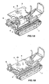
- Crawlers 2 support a self-propelled chassis 8, onto which the cab 6 is provided, and comprising a motor and all the controls of device for grasping, lifting, and/or moving loads 3A, provided on the chassis 8 opposite the cab 6.
- Such device 3A comprises a telescopically extensible arm 5, formed by two parts 5a and 5b, articulated at the base to a support plate 9 in correspondence of a hinge structure 5c.
- the arm 5 On its distal end, the arm 5 has a pair of forks 4a associated to a stopping bulkhead 13.
- the forks 4a are of the type apt to lift standard pallets. Nevertheless, the device for grasping, lifting, and/or moving loads 3 could comprise any other loading implement.
- forks 4a and bulkhead 13 are articulated at the telescopic arm 5 distal end, and they can be controlled in their rotation above an horizontal axis, i.e. a hinge 15 onto which suitable actuators are mounted (not shown).
- the lifter 1 comprises drive means, apt to rotate the support plate 9.
- said drive means comprises a fifth wheel 10 fixed to the plate 9 by means of crown-disposed bolts.
- the fifth wheel 10 is rotated by a motor-driven pinion gear 11.
- the plate 9 receives said lifting device 3 and the respective controls thereon, so that the hopper 3 could be rotated relative to chassis 8 and crawlers, opposite to the operator.
- the rotation axis A of the fifth wheel 10 is substantially centered to the plate 9, in a vertical position.
- the plate 9 has an extension 9a placed according to a configuration opposed to the direction in to which the arm 4 projects. It comprises a mobile compensator 14 that is translated according to the position of the arm 5, fork 4a and of the load lifted therefrom.
- the compensator 14 could be extensible.
- shape of the device for grasping, lifting, and/or moving loads could be varied as preferred in order to satisfy any operative requirement.
- the vehicle comprises a lifting device 3a, the lifting member thereof being formed by a bucket 4b articulated to a telescopically arm 5 distal end.
- the bucket 4b can thus be operated in its rotation above an horizontal axis, i.e. a hinge 15 in correspondence of which suitable actuators (not shown) are mounted, for simplifying the loading of the material to be displaced.
- the vehicle of figure 8 is provided with a telescopic arm supporting a lifting platform 4c, also articulated to the arm 5 distal so that it can be always maintained horizontal.
- the platform 4c can be formed by a safety cage.
- a self-propelled vehicle analogous to the preceding ones, comprises, at the telescopically arm 5 distal end, a hoist 4d provided with a hook 16 connected to a cable 17 end.
- the hoist 4d could be obviously also replaced by a winch or by any other lifting member.
- the operating cab 6 is disposed on the chassis 8 and not on the rotating plate 9. Nevertheless, according to a modification of the invention, the cab 6 could be disposed above the plate 9 and together rotated, so that the operator is always directed towards the implemented mounted on the vehicle.
- the compensator could be mounted at the back of the operating cab, and could be extensible rearwards, with an improved efficiency thanks to the rocker arm accordingly defined.
- the distance of the balance weight at the vehicle center could be manually modified by means by means of an automatic servomechanism, for enhancing balancing momentum.
- any of above described vehicle could be provided with stabilizing feet. Moreover, they can be provided with an universal quick coupling for a quick changing of implement at the arm.
- the crawler mounted vehicle could be of the fixed track-gauge type, variable track-gauge type or variable and/or enlarged track-gauge type.
Landscapes
- Engineering & Computer Science (AREA)
- Structural Engineering (AREA)
- Mechanical Engineering (AREA)
- Civil Engineering (AREA)
- Mining & Mineral Resources (AREA)
- General Engineering & Computer Science (AREA)
- Life Sciences & Earth Sciences (AREA)
- Geology (AREA)
- Transportation (AREA)
- Jib Cranes (AREA)
Applications Claiming Priority (2)
| Application Number | Priority Date | Filing Date | Title |
|---|---|---|---|
| ITRM20070558 ITRM20070558A1 (it) | 2007-10-24 | 2007-10-24 | Dumper autocaricante con cassone girevole |
| ITRM20070235 ITRM20070235U1 (it) | 2007-12-17 | 2007-12-17 | Sollevatore semovente |
Publications (1)
| Publication Number | Publication Date |
|---|---|
| EP2080730A1 true EP2080730A1 (fr) | 2009-07-22 |
Family
ID=40679848
Family Applications (1)
| Application Number | Title | Priority Date | Filing Date |
|---|---|---|---|
| EP08167550A Withdrawn EP2080730A1 (fr) | 2007-10-24 | 2008-10-24 | Véhicule industriel autopropulsé |
Country Status (1)
| Country | Link |
|---|---|
| EP (1) | EP2080730A1 (fr) |
Cited By (9)
| Publication number | Priority date | Publication date | Assignee | Title |
|---|---|---|---|---|
| CN102817390A (zh) * | 2011-04-14 | 2012-12-12 | 哈尼施费格尔技术公司 | 绳索挖掘机的回转自动化 |
| KR101329294B1 (ko) | 2011-12-26 | 2013-11-13 | 윤길수 | 포크를 구비하는 굴삭기 |
| EP3034357A1 (fr) * | 2014-12-17 | 2016-06-22 | Cormidi S.r.l. | Porte-outil pour véhicules automoteurs, véhicule automoteur |
| CN105984164A (zh) * | 2015-02-10 | 2016-10-05 | 上海润寅制药设备有限公司 | 专用于医药生产的自动提升机 |
| US9745721B2 (en) | 2012-03-16 | 2017-08-29 | Harnischfeger Technologies, Inc. | Automated control of dipper swing for a shovel |
| KR20180003062U (ko) * | 2018-01-02 | 2018-10-24 | 김대길 | 굴착기용 지게차 어태치먼트 |
| CN114215132A (zh) * | 2021-10-21 | 2022-03-22 | 朱伟燕 | 一种水利施工用排淤系统 |
| WO2022240208A1 (fr) * | 2021-05-13 | 2022-11-17 | 현대두산인프라코어(주) | Système de commande d'excavatrice et procédé de commande d'excavatrice l'utilisant |
| US11565922B2 (en) * | 2018-03-30 | 2023-01-31 | Manitou Italia S.R.L. | Remote controlled telehandler |
Citations (9)
| Publication number | Priority date | Publication date | Assignee | Title |
|---|---|---|---|---|
| US2790568A (en) * | 1955-06-30 | 1957-04-30 | Vernon G Mandt | Swing-type material moving machine |
| US3240353A (en) * | 1963-03-08 | 1966-03-15 | Leavesley Engineering Ltd | Load responsive counterbalancing crane |
| US3329291A (en) * | 1965-08-27 | 1967-07-04 | Warner Swasey Co | Material handling apparatus |
| US3484005A (en) * | 1966-04-28 | 1969-12-16 | Poclain Sa | Earth working machine |
| GB1225268A (fr) * | 1967-03-01 | 1971-03-17 | ||
| US4044902A (en) * | 1975-09-22 | 1977-08-30 | General Cable Corporation | Aerial lifting equipment |
| EP0184386A1 (fr) * | 1984-12-01 | 1986-06-11 | J.C. Bamford Excavators Limited | Machine de terrassement avec contrepoids |
| DE3611432A1 (de) * | 1986-04-05 | 1987-11-12 | Schaeff Karl Gmbh & Co | Schwenkantrieb fuer eine drehbare plattform oder dergleichen trageinrichtung, insbesondere fuer den drehschemel eines schwenkschaufelladers |
| EP0156546B1 (fr) * | 1984-03-06 | 1988-09-28 | Kabushiki Kaisha Hikoma Seisakusho | Engin de terrassement |
-
2008
- 2008-10-24 EP EP08167550A patent/EP2080730A1/fr not_active Withdrawn
Patent Citations (9)
| Publication number | Priority date | Publication date | Assignee | Title |
|---|---|---|---|---|
| US2790568A (en) * | 1955-06-30 | 1957-04-30 | Vernon G Mandt | Swing-type material moving machine |
| US3240353A (en) * | 1963-03-08 | 1966-03-15 | Leavesley Engineering Ltd | Load responsive counterbalancing crane |
| US3329291A (en) * | 1965-08-27 | 1967-07-04 | Warner Swasey Co | Material handling apparatus |
| US3484005A (en) * | 1966-04-28 | 1969-12-16 | Poclain Sa | Earth working machine |
| GB1225268A (fr) * | 1967-03-01 | 1971-03-17 | ||
| US4044902A (en) * | 1975-09-22 | 1977-08-30 | General Cable Corporation | Aerial lifting equipment |
| EP0156546B1 (fr) * | 1984-03-06 | 1988-09-28 | Kabushiki Kaisha Hikoma Seisakusho | Engin de terrassement |
| EP0184386A1 (fr) * | 1984-12-01 | 1986-06-11 | J.C. Bamford Excavators Limited | Machine de terrassement avec contrepoids |
| DE3611432A1 (de) * | 1986-04-05 | 1987-11-12 | Schaeff Karl Gmbh & Co | Schwenkantrieb fuer eine drehbare plattform oder dergleichen trageinrichtung, insbesondere fuer den drehschemel eines schwenkschaufelladers |
Cited By (16)
| Publication number | Priority date | Publication date | Assignee | Title |
|---|---|---|---|---|
| US12018463B2 (en) | 2011-04-14 | 2024-06-25 | Joy Global Surface Mining Inc | Swing automation for rope shovel |
| US9315967B2 (en) | 2011-04-14 | 2016-04-19 | Harnischfeger Technologies, Inc. | Swing automation for rope shovel |
| US9567725B2 (en) | 2011-04-14 | 2017-02-14 | Harnischfeger Technologies, Inc. | Swing automation for rope shovel |
| CN102817390B (zh) * | 2011-04-14 | 2017-04-12 | 哈尼施费格尔技术公司 | 绳索挖掘机的回转自动化 |
| CN102817390A (zh) * | 2011-04-14 | 2012-12-12 | 哈尼施费格尔技术公司 | 绳索挖掘机的回转自动化 |
| US10227754B2 (en) | 2011-04-14 | 2019-03-12 | Joy Global Surface Mining Inc | Swing automation for rope shovel |
| US11028560B2 (en) | 2011-04-14 | 2021-06-08 | Joy Global Surface Mining Inc | Swing automation for rope shovel |
| KR101329294B1 (ko) | 2011-12-26 | 2013-11-13 | 윤길수 | 포크를 구비하는 굴삭기 |
| US9745721B2 (en) | 2012-03-16 | 2017-08-29 | Harnischfeger Technologies, Inc. | Automated control of dipper swing for a shovel |
| US10655301B2 (en) | 2012-03-16 | 2020-05-19 | Joy Global Surface Mining Inc | Automated control of dipper swing for a shovel |
| EP3034357A1 (fr) * | 2014-12-17 | 2016-06-22 | Cormidi S.r.l. | Porte-outil pour véhicules automoteurs, véhicule automoteur |
| CN105984164A (zh) * | 2015-02-10 | 2016-10-05 | 上海润寅制药设备有限公司 | 专用于医药生产的自动提升机 |
| KR20180003062U (ko) * | 2018-01-02 | 2018-10-24 | 김대길 | 굴착기용 지게차 어태치먼트 |
| US11565922B2 (en) * | 2018-03-30 | 2023-01-31 | Manitou Italia S.R.L. | Remote controlled telehandler |
| WO2022240208A1 (fr) * | 2021-05-13 | 2022-11-17 | 현대두산인프라코어(주) | Système de commande d'excavatrice et procédé de commande d'excavatrice l'utilisant |
| CN114215132A (zh) * | 2021-10-21 | 2022-03-22 | 朱伟燕 | 一种水利施工用排淤系统 |
Similar Documents
| Publication | Publication Date | Title |
|---|---|---|
| EP2080730A1 (fr) | Véhicule industriel autopropulsé | |
| US6571913B2 (en) | Multipurpose machine | |
| AU2002329704A1 (en) | Multipurpose machine | |
| EP0931759B1 (fr) | Flèche latérale pour plateforme de travail mobile à mât vertical | |
| KR20080038034A (ko) | 가변 위치 균형추를 포함하는 이동식 리프트 크레인 | |
| CA1148122A (fr) | Vehicule utilitaire tous usages | |
| CN105152081A (zh) | 侧后向旋转作业伸缩式叉车 | |
| US20050016946A1 (en) | Telehandler crane apparatus | |
| JP4462633B2 (ja) | パレットトラック | |
| US7384233B2 (en) | Industrial truck | |
| JP2022541549A (ja) | パレットを持ち上げるリフト装置を有する掘削機 | |
| EP0568758A1 (fr) | Elevateur-excavatrice mobile à usage multiple | |
| AU2020367535B2 (en) | Mobile crane | |
| CN106006438B (zh) | 一种多功能液压起重机 | |
| JP7392820B2 (ja) | クレーンの連結ビーム取付方法 | |
| US7163112B2 (en) | Material transloading equipment | |
| US3504815A (en) | Tandem wheel steering mechanism for a lift vehicle | |
| NL1036935C2 (nl) | Hefinrichting en heforgaan voor toepassing in een hefinrichting. | |
| GB2066189A (en) | Multi-purpose utility vehicle | |
| EP3405620B1 (fr) | Véhicule chargeur | |
| JPH1054055A (ja) | 作業機の昇降制御装置 | |
| EP0080002B1 (fr) | Grue de chantier mobile pour la manutention de containers | |
| US12473707B2 (en) | Material handler skip pan | |
| US12202710B2 (en) | Crane | |
| JP7208821B2 (ja) | 作業車 |
Legal Events
| Date | Code | Title | Description |
|---|---|---|---|
| PUAI | Public reference made under article 153(3) epc to a published international application that has entered the european phase |
Free format text: ORIGINAL CODE: 0009012 |
|
| AK | Designated contracting states |
Kind code of ref document: A1 Designated state(s): AT BE BG CH CY CZ DE DK EE ES FI FR GB GR HR HU IE IS IT LI LT LU LV MC MT NL NO PL PT RO SE SI SK TR |
|
| AX | Request for extension of the european patent |
Extension state: AL BA MK RS |
|
| AKX | Designation fees paid | ||
| REG | Reference to a national code |
Ref country code: DE Ref legal event code: 8566 |
|
| STAA | Information on the status of an ep patent application or granted ep patent |
Free format text: STATUS: THE APPLICATION IS DEEMED TO BE WITHDRAWN |
|
| 18D | Application deemed to be withdrawn |
Effective date: 20100123 |