EP2080866A2 - Élément de couplage pour traverses de cadres métalliques pour portes et/ou battants de portes - Google Patents
Élément de couplage pour traverses de cadres métalliques pour portes et/ou battants de portes Download PDFInfo
- Publication number
- EP2080866A2 EP2080866A2 EP20080172495 EP08172495A EP2080866A2 EP 2080866 A2 EP2080866 A2 EP 2080866A2 EP 20080172495 EP20080172495 EP 20080172495 EP 08172495 A EP08172495 A EP 08172495A EP 2080866 A2 EP2080866 A2 EP 2080866A2
- Authority
- EP
- European Patent Office
- Prior art keywords
- coupling element
- crosspiece
- pressure
- upright
- insertable
- Prior art date
- Legal status (The legal status is an assumption and is not a legal conclusion. Google has not performed a legal analysis and makes no representation as to the accuracy of the status listed.)
- Withdrawn
Links
- 230000008878 coupling Effects 0.000 title claims abstract description 20
- 238000010168 coupling process Methods 0.000 title claims abstract description 20
- 238000005859 coupling reaction Methods 0.000 title claims abstract description 20
- 239000002184 metal Substances 0.000 title claims abstract description 9
- 230000037431 insertion Effects 0.000 claims description 4
- 238000003780 insertion Methods 0.000 claims description 4
- 239000000463 material Substances 0.000 claims description 3
- 230000000903 blocking effect Effects 0.000 claims description 2
- 239000011521 glass Substances 0.000 description 1
- 230000005484 gravity Effects 0.000 description 1
Images

Classifications
-
- E—FIXED CONSTRUCTIONS
- E06—DOORS, WINDOWS, SHUTTERS, OR ROLLER BLINDS IN GENERAL; LADDERS
- E06B—FIXED OR MOVABLE CLOSURES FOR OPENINGS IN BUILDINGS, VEHICLES, FENCES OR LIKE ENCLOSURES IN GENERAL, e.g. DOORS, WINDOWS, BLINDS, GATES
- E06B3/00—Window sashes, door leaves, or like elements for closing wall or like openings; Layout of fixed or moving closures, e.g. windows in wall or like openings; Features of rigidly-mounted outer frames relating to the mounting of wing frames
- E06B3/96—Corner joints or edge joints for windows, doors, or the like frames or wings
- E06B3/964—Corner joints or edge joints for windows, doors, or the like frames or wings using separate connection pieces, e.g. T-connection pieces
- E06B3/9642—Butt type joints with at least one frame member cut off square; T-shape joints
-
- E—FIXED CONSTRUCTIONS
- E06—DOORS, WINDOWS, SHUTTERS, OR ROLLER BLINDS IN GENERAL; LADDERS
- E06B—FIXED OR MOVABLE CLOSURES FOR OPENINGS IN BUILDINGS, VEHICLES, FENCES OR LIKE ENCLOSURES IN GENERAL, e.g. DOORS, WINDOWS, BLINDS, GATES
- E06B1/00—Border constructions of openings in walls, floors, or ceilings; Frames to be rigidly mounted in such openings
- E06B1/04—Frames for doors, windows, or the like to be fixed in openings
- E06B1/52—Frames specially adapted for doors
- E06B1/524—Mullions; Transoms
-
- E—FIXED CONSTRUCTIONS
- E06—DOORS, WINDOWS, SHUTTERS, OR ROLLER BLINDS IN GENERAL; LADDERS
- E06B—FIXED OR MOVABLE CLOSURES FOR OPENINGS IN BUILDINGS, VEHICLES, FENCES OR LIKE ENCLOSURES IN GENERAL, e.g. DOORS, WINDOWS, BLINDS, GATES
- E06B3/00—Window sashes, door leaves, or like elements for closing wall or like openings; Layout of fixed or moving closures, e.g. windows in wall or like openings; Features of rigidly-mounted outer frames relating to the mounting of wing frames
- E06B3/96—Corner joints or edge joints for windows, doors, or the like frames or wings
- E06B3/964—Corner joints or edge joints for windows, doors, or the like frames or wings using separate connection pieces, e.g. T-connection pieces
- E06B3/968—Corner joints or edge joints for windows, doors, or the like frames or wings using separate connection pieces, e.g. T-connection pieces characterised by the way the connecting pieces are fixed in or on the frame members
- E06B3/9681—Corner joints or edge joints for windows, doors, or the like frames or wings using separate connection pieces, e.g. T-connection pieces characterised by the way the connecting pieces are fixed in or on the frame members by press fit or adhesion
-
- E—FIXED CONSTRUCTIONS
- E06—DOORS, WINDOWS, SHUTTERS, OR ROLLER BLINDS IN GENERAL; LADDERS
- E06B—FIXED OR MOVABLE CLOSURES FOR OPENINGS IN BUILDINGS, VEHICLES, FENCES OR LIKE ENCLOSURES IN GENERAL, e.g. DOORS, WINDOWS, BLINDS, GATES
- E06B3/00—Window sashes, door leaves, or like elements for closing wall or like openings; Layout of fixed or moving closures, e.g. windows in wall or like openings; Features of rigidly-mounted outer frames relating to the mounting of wing frames
- E06B3/96—Corner joints or edge joints for windows, doors, or the like frames or wings
- E06B3/964—Corner joints or edge joints for windows, doors, or the like frames or wings using separate connection pieces, e.g. T-connection pieces
- E06B3/968—Corner joints or edge joints for windows, doors, or the like frames or wings using separate connection pieces, e.g. T-connection pieces characterised by the way the connecting pieces are fixed in or on the frame members
- E06B3/9684—Corner joints or edge joints for windows, doors, or the like frames or wings using separate connection pieces, e.g. T-connection pieces characterised by the way the connecting pieces are fixed in or on the frame members by hooking protrusions on the connecting piece in openings of the frame member, e.g. by snap-locking
Definitions
- the present invention relates to a coupling element for crosspieces of metal frames for doors and/or door leaves.
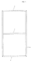
- Metal frames for doors and/or door leaves consisting substantially of two uprights connected together at their ends by double angle stringers and defining a space which is generally filled with panelling of glass or other material.
- the two uprights are connected together along the centre line by a crosspiece.
- the crosspiece is formed from a tubular profile provided internally with two curved longitudinal projections which overall form a cylindrical seat.
- the crosspiece is also provided externally with a T-profile acting as a support for the panelling.
- connection between the crosspiece and the upright is made by forming a hole in the facing walls of the uprights, inserting a threaded pin through these, applying the crosspiece to the threaded pin and locking the crosspiece to the threaded pin by means of a grub screw which engages them both.
- Another system consists of applying to the ends of the uprights a threaded pin which also engages in the circular seat of the crosspiece.
- a further system consists of fixing the crosspiece to the upright by means of a screw, by making a through hole in both sides of the upright.
- An object of the invention is to eliminate these drawbacks by providing a coupling element which can be easily applied to the upright and/or to the crosspiece and is of low cost.
- Another object of the invention is to provide a coupling element which enables the upright and crosspiece to be easily connected together and be rapidly disassembled.
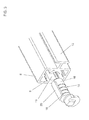
- the coupling element of the invention is applied in metal frames consisting of two uprights joined together by angle stringers 4, to connect the central crosspiece 6 to the facing surfaces of the upright 2.
- the crosspiece 6 consists of a tubular profile of substantially rectangular cross-section provided internally with curved projections 8 which form overall a cylindrical seat 10, and provided externally with a T-profile 12 for fixing the panelling.
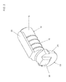
- the coupling element of the invention comprises substantially a plastic or metal cylindrical body 16, provided with a plurality of circumferential ribs 18 and a tang 20 the width of which corresponds substantially to the distance between the facing edges of the curved projections 8.
- the cylindrical body 16 extends at one end into a second body 22 consisting substantially of a first semi-cylindrical stepped portion 24, a second cylindrical portion 26 the diameter of which corresponds to the diameter of the hole 28 of the upright 2, and an abutment portion 30.
- the coupling element of the invention is used in the following manner: it is inserted with its cylindrical body 16 into the seat 10 such that the tang 20 is disposed between the facing edges of the projections 8.
- This insertion operation is carried out by striking against the portion 30 with a hammer to cause forced insertion, which is resisted by the presence of the ribs 18 within the seat 10.
- the cylindrical portion is inserted through the hole formed therein, and after passing beyond the thickness of the upright it rests by gravity with the portion 26 on the edge of the hole 28.
Landscapes
- Engineering & Computer Science (AREA)
- Civil Engineering (AREA)
- Structural Engineering (AREA)
- Mutual Connection Of Rods And Tubes (AREA)
Applications Claiming Priority (1)
| Application Number | Priority Date | Filing Date | Title |
|---|---|---|---|
| ITVE20080001 ITVE20080001A1 (it) | 2008-01-21 | 2008-01-21 | Elemento di aggancio per traversini di telai metallici per porte e/o ante.- |
Publications (1)
| Publication Number | Publication Date |
|---|---|
| EP2080866A2 true EP2080866A2 (fr) | 2009-07-22 |
Family
ID=40290469
Family Applications (1)
| Application Number | Title | Priority Date | Filing Date |
|---|---|---|---|
| EP20080172495 Withdrawn EP2080866A2 (fr) | 2008-01-21 | 2008-12-22 | Élément de couplage pour traverses de cadres métalliques pour portes et/ou battants de portes |
Country Status (2)
| Country | Link |
|---|---|
| EP (1) | EP2080866A2 (fr) |
| IT (1) | ITVE20080001A1 (fr) |
Cited By (1)
| Publication number | Priority date | Publication date | Assignee | Title |
|---|---|---|---|---|
| WO2025120325A1 (fr) * | 2023-12-08 | 2025-06-12 | Louver-Lite Limited | Système d'ensemble cadre et procédé d'assemblage d'un cadre |
-
2008
- 2008-01-21 IT ITVE20080001 patent/ITVE20080001A1/it unknown
- 2008-12-22 EP EP20080172495 patent/EP2080866A2/fr not_active Withdrawn
Cited By (2)
| Publication number | Priority date | Publication date | Assignee | Title |
|---|---|---|---|---|
| WO2025120325A1 (fr) * | 2023-12-08 | 2025-06-12 | Louver-Lite Limited | Système d'ensemble cadre et procédé d'assemblage d'un cadre |
| GB2636380A (en) * | 2023-12-08 | 2025-06-18 | Louver Lite Ltd | A frame assembly system |
Also Published As
| Publication number | Publication date |
|---|---|
| ITVE20080001A1 (it) | 2009-07-22 |
Similar Documents
| Publication | Publication Date | Title |
|---|---|---|
| EP0501994B1 (fr) | Piece moulee pour le raccordement de profiles de construction | |
| EP2373858B1 (fr) | Support de poignée, appareil électroménager et procédé de fixation d'une poignée de porte | |
| EP2636839B1 (fr) | Pièce statique pour un coffre de volet roulant | |
| EP1020575B1 (fr) | Connection en T entre un poteau et une traverse profilés d'une façade ou d'une toiture vitrée | |
| DE102011080795B3 (de) | Befestigungsanordnung zur Befestigung eines Bauteils an einer Nut eines Fensters, einer Tür oder dergleichen | |
| RU2469163C2 (ru) | Петля для металлических дверных или оконных блоков | |
| DE102011000881B4 (de) | Lagerbock und Ausstelleinrichtung | |
| CA2988733A1 (fr) | Cadre de porte escamotable ajustable compact | |
| AT397281B (de) | Verglaste und/oder mit füllung versehene brandschutztüre | |
| EP2045430A2 (fr) | Demi-coque pour la formation d'une porte et des cadres de fenêtres, ou similaire d'isolation thermique, section correspondante et procédé d'assemblage correspondant | |
| AU736455B2 (en) | Closure sleeve for a clamping device for the releasable connection of two profile pieces | |
| CN101666345A (zh) | 凹槽螺母 | |
| DE19816365A1 (de) | Verschwindscharnier | |
| DE4012808C2 (de) | Verbindungsformstück für Bauprofile | |
| EP3447223B1 (fr) | Partie d'une bande charnière | |
| DE2302235C3 (de) | Rahmenprofil für Fenster, Türen o.dgl | |
| EP1445409B1 (fr) | Elément de support et réception pour charnières | |
| EP2993428B1 (fr) | Porte d'un appareil menager dotée d'un revêtement | |
| DE19634322A1 (de) | Vitrine | |
| AT508729B1 (de) | Zarge für flächenbündigen einbau eines monoblockfensters | |
| AT511727B1 (de) | Fensterrahmen aus faserverstärktem kunststoff | |
| AU2021206894A1 (en) | Adjustable Wings Including Adjustable Doors & Screens | |
| EP3389459B1 (fr) | Connection angulaire supérieure de cabine de douche | |
| EP2009206A1 (fr) | Élément de fixation pour fixer une charnière sur le montant d'une porte ou cadre de fenêtre ou similaire | |
| DE202007015993U1 (de) | Profilsystem zur Halterung von Duschtrennwänden |
Legal Events
| Date | Code | Title | Description |
|---|---|---|---|
| PUAI | Public reference made under article 153(3) epc to a published international application that has entered the european phase |
Free format text: ORIGINAL CODE: 0009012 |
|
| AK | Designated contracting states |
Kind code of ref document: A2 Designated state(s): AT BE BG CH CY CZ DE DK EE ES FI FR GB GR HR HU IE IS IT LI LT LU LV MC MT NL NO PL PT RO SE SI SK TR |
|
| AX | Request for extension of the european patent |
Extension state: AL BA MK RS |
|
| STAA | Information on the status of an ep patent application or granted ep patent |
Free format text: STATUS: THE APPLICATION IS DEEMED TO BE WITHDRAWN |
|
| 18D | Application deemed to be withdrawn |
Effective date: 20120703 |