EP2080910A2 - Ventilateur, notamment pour la ventilation de véhicules - Google Patents
Ventilateur, notamment pour la ventilation de véhicules Download PDFInfo
- Publication number
- EP2080910A2 EP2080910A2 EP08020487A EP08020487A EP2080910A2 EP 2080910 A2 EP2080910 A2 EP 2080910A2 EP 08020487 A EP08020487 A EP 08020487A EP 08020487 A EP08020487 A EP 08020487A EP 2080910 A2 EP2080910 A2 EP 2080910A2
- Authority
- EP
- European Patent Office
- Prior art keywords
- impeller
- blower
- intake
- axis
- rotation
- Prior art date
- Legal status (The legal status is an assumption and is not a legal conclusion. Google has not performed a legal analysis and makes no representation as to the accuracy of the status listed.)
- Granted
Links
- 238000009423 ventilation Methods 0.000 title description 3
- 238000004378 air conditioning Methods 0.000 claims description 8
- 230000003134 recirculating effect Effects 0.000 description 4
- 239000007789 gas Substances 0.000 description 2
- 230000004941 influx Effects 0.000 description 2
- 230000001419 dependent effect Effects 0.000 description 1
- 238000005516 engineering process Methods 0.000 description 1
- 239000012530 fluid Substances 0.000 description 1
- 230000005484 gravity Effects 0.000 description 1
- 238000010438 heat treatment Methods 0.000 description 1
- 239000000126 substance Substances 0.000 description 1
- XLYOFNOQVPJJNP-UHFFFAOYSA-N water Substances O XLYOFNOQVPJJNP-UHFFFAOYSA-N 0.000 description 1
Images

Classifications
-
- F—MECHANICAL ENGINEERING; LIGHTING; HEATING; WEAPONS; BLASTING
- F04—POSITIVE - DISPLACEMENT MACHINES FOR LIQUIDS; PUMPS FOR LIQUIDS OR ELASTIC FLUIDS
- F04D—NON-POSITIVE-DISPLACEMENT PUMPS
- F04D29/00—Details, component parts, or accessories
- F04D29/40—Casings; Connections of working fluid
- F04D29/42—Casings; Connections of working fluid for radial or helico-centrifugal pumps
- F04D29/4206—Casings; Connections of working fluid for radial or helico-centrifugal pumps especially adapted for elastic fluid pumps
- F04D29/4226—Fan casings
-
- F—MECHANICAL ENGINEERING; LIGHTING; HEATING; WEAPONS; BLASTING
- F04—POSITIVE - DISPLACEMENT MACHINES FOR LIQUIDS; PUMPS FOR LIQUIDS OR ELASTIC FLUIDS
- F04D—NON-POSITIVE-DISPLACEMENT PUMPS
- F04D29/00—Details, component parts, or accessories
- F04D29/40—Casings; Connections of working fluid
- F04D29/42—Casings; Connections of working fluid for radial or helico-centrifugal pumps
- F04D29/4206—Casings; Connections of working fluid for radial or helico-centrifugal pumps especially adapted for elastic fluid pumps
- F04D29/4226—Fan casings
- F04D29/424—Double entry casings
Definitions
- the invention relates to a fan, in particular for the fresh and / or Um Kunststoffansaugung a vehicle air conditioning system, according to the preamble of claim 1.
- the DE 1 428 085 A1 discloses a tumbler fan with a housing which is substantially open on one side and sucks air from there.
- the impeller runs partially free, ie without a cover.
- an outer guide surface is provided which comprises approximately half of the impeller circumference.
- the air intake takes place via the open area of the blower in both the radial and axial directions.
- blower arrangement for the fresh and / or Um Kunststoffansaugung a vehicle air conditioning system known, said blower arrangement each having separate wheels for fresh and circulating air both on the driver and on the passenger side.
- the invention relates to a fan, in particular for the fresh and / or Um Kunststoffansaugung for a vehicle air conditioner, with a blower housing, an impeller with a rotation axis and the impeller driving fan motor, wherein the fan housing at least one suction port for an intake port and a Austriftsö réelle for an outlet channel having.
- the surface normal to the intake opening of the intake duct is skewed with respect to the axis of rotation of the impeller and the intake opening is arranged in a direction offset in the direction of the axis of rotation of the impeller to the outlet opening.
- the lateral influx of air causes a pre-whirl and thus improves the inflow to the impeller or impeller blading. Speed peaks when flowing around the Zargenrandes by strong deflection can be avoided, resulting in a noise reduction.
- the surface normal to the suction opening is arranged parallel to a plane in which the axis of rotation of the impeller is, wherein the central longitudinal axis of the intake passage is arranged in particular approximately tangentially to the preferably circular inlet opening to the impeller.
- a plane in which a suction port is located preferably includes the axis of rotation of the impeller.
- the intake channel in a plane which extends perpendicular to the axis of rotation of the impeller has a width which corresponds at most to the width of the inlet opening or, in the case of a circular opening, to the diameter of the inlet opening to the impeller.
- the fan motor is preferably located on the opposite side of the impeller with respect to the intake passage (s).
- Two intake ducts in particular a fresh air duct and a recirculating air duct, are particularly preferably provided so that intake from two directions can be realized.
- the surface normals of the suction openings are advantageously arranged at an angle of 0 ° to 90 ° to each other.
- the suction openings are arranged on opposite sides of the axis of rotation of the impeller and extend in particular in a plane.
- the intake ports are formed in a Zuströmgephaseuse, wherein the Zuströmgephaseuse preferably connects in the axial direction of the axis of rotation of the impeller to the fan housing.
- the inflow housing and the blower housing are formed as separate components, wherein the inflow housing is an attachment or stem to the blower housing.
- the intake ducts are preferably arranged uniformly over the circumference of an inlet opening to the impeller. In the case of two intake ducts, they are located diagonally opposite one another, the central longitudinal axes of the two intake ducts being arranged parallel to one another and spaced from one another in accordance with a preferred embodiment. Here, a parallel arrangement of the intake ports to each other is possible.
- blower is preferably used in a vehicle air conditioner, however, the blower may also be used, for example, for a pure heating or ventilation system of a vehicle. Likewise, the blower can also be used in the chemical industry for the promotion of gases or in the ventilation technology.
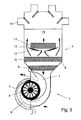
- a blower 1 of a vehicle air conditioning system 2 has an impeller 4 arranged in a blower housing 3 and a blower motor 5.
- the blower 1 sucks controlled via the flaps (not shown) air from the environment (fresh air) via a fresh air duct 6a and air from the vehicle interior (circulating air) via a circulating air duct 6b.
- the two air ducts will hereinafter also be referred to as intake air ducts.
- the intake air ducts 6a, 6b are formed in a Zuströmgephaseuse 22 which is connected as an attachment to the fan housing 3. In the parting plane between the Zuströmgepatuse 22 and blower housing 3, the actual inlet opening 23 of the blower is.
- the regulation of the temperature is carried out in a conventional manner by means of temperature mixing flaps 12, which distribute the cold, coming from the evaporator 10 air flow to the radiator 11 and bypasses 13.
- the thus different tempered partial air streams are mixed in the mixing chamber 14 arranged below and fed to the various areas of the vehicle interior via flap-controlled outlet openings and air ducts 15.
- the embodiment of the air conditioner 2 may be provided deviating from the embodiment in any conventional manner.
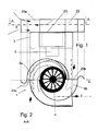
- blower 1 For the description of the blower 1 is hereinafter referred to the Figures 1 and 2 Reference is made, for better clarity in the drawing, the figures are interconnected by dashed lines shown gravity lines.
- the flow patterns of the air are at the entrances and exits from Fig. 2 and at the entrance of the fresh air channel 6a of Fig. 1 illustrated by arrows.
- Fig. 1 how out Fig. 1 can be seen, the fan housing on three stages, in the uppermost stage, the Zuströmgepatuse 22, the fresh and the recirculating air duct 6a, 6b open and the air flow is slightly deflected. In the second, middle stage, the actual volute casing of the blower 1 together with the impeller 4 and the outlet (outlet air duct 7) is arranged. Below this, the blower motor 5 is arranged in the third stage.
- the flow is in this case in the middle perpendicular to the radial direction, the center of the air channels 6 is clearly offset with respect to the impeller 4 to the outside.
- the impeller 4 closest to the wall is slightly offset to the outside.
- the inlet of the air to be conveyed into the corresponding intake ducts 6a, 6b takes place through the associated intake openings 20a, 20b, wherein in the present case the surface normals are arranged on these intake openings 20a, 20b parallel to each other and perpendicular to the rotor axis.
- these surface normals are shown as dash-dotted lines and perpendicular to the respective intake opening 20a, 20b and extending through the center of area thereof.
- the intake openings lie in a common plane, in which the axis of the impeller 4 is located.
- the surface normal through the outlet opening 21 is substantially perpendicular to the surface normals of the suction openings 20a, 20b and to the axis of the impeller 4.
- the sum of the cross section of the intake openings 20a, 20b which in a plane E (see Fig. 2 ), according to the present embodiment corresponds approximately to the cross-sectional area of the impeller in the corresponding plane E, in which also lies the axis of rotation, or substantially the cross section of the inlet opening 23.
- the two intake air ducts 6 spiral the sucked air to the impeller 4, wherein It passes through the above-arranged circular inlet opening 23 - also referred to as a frame opening - from the intake air ducts 6a, 6b to the impeller 4.
- the spiral-shaped configuration of the intake air ducts 6a, 6b generates a pre-whirl which, superimposed with a relatively small linear component, is continued through the door opening and improves the inflow to the impeller blading.
- the air does not move directly to the Zargenö réelle 23, but flows - seen with respect to the center of the intake air duct 6 - tangentially thereto, wherein a total of one skew arrangement of the axis of rotation of the impeller 4 (center of the Zargenö réelle) and the surface normal on the suction port 21 a, 21 b of an intake passage 6 is present.
- Such a configuration results in a vortex-like rotational movement into the frame opening.
- an air blower is provided, however, a corresponding embodiment for other fluids, such as. Gases or water, applicable and also not necessarily limited to air conditioning.
- the fan housing has three stages, wherein in the uppermost stage, the Zuströmgepatuse 22, the fresh and the recirculating air duct 6a, 6b open and the air flow is slightly deflected.
- the suction openings 20a, 20b are no longer inclined in a common, but at an angle of about 80 ° to each other.
- This also applies to the corresponding surface normals, which in Fig. 5 again shown as dash-dotted lines.
- the suction port 20a formed on the left side is opposed to the suction port 20b on the right side in a plane offset from the rotation axis.
- the axis of rotation of the impeller 4 is also parallel to this plane.
Landscapes
- Engineering & Computer Science (AREA)
- Mechanical Engineering (AREA)
- General Engineering & Computer Science (AREA)
- Structures Of Non-Positive Displacement Pumps (AREA)
Applications Claiming Priority (1)
| Application Number | Priority Date | Filing Date | Title |
|---|---|---|---|
| DE102008004746A DE102008004746A1 (de) | 2008-01-16 | 2008-01-16 | Gebläse, insbesondere für die Frisch- und/oder Umluftansaugung einer Fahrzeugklimaanlage |
Publications (3)
| Publication Number | Publication Date |
|---|---|
| EP2080910A2 true EP2080910A2 (fr) | 2009-07-22 |
| EP2080910A3 EP2080910A3 (fr) | 2013-11-06 |
| EP2080910B1 EP2080910B1 (fr) | 2018-06-20 |
Family
ID=40139929
Family Applications (1)
| Application Number | Title | Priority Date | Filing Date |
|---|---|---|---|
| EP08020487.8A Ceased EP2080910B1 (fr) | 2008-01-16 | 2008-11-26 | Ventilateur, notamment pour la ventilation de véhicules |
Country Status (2)
| Country | Link |
|---|---|
| EP (1) | EP2080910B1 (fr) |
| DE (1) | DE102008004746A1 (fr) |
Cited By (1)
| Publication number | Priority date | Publication date | Assignee | Title |
|---|---|---|---|---|
| US20160153666A1 (en) * | 2013-09-10 | 2016-06-02 | Electrolux Appliances Aktiebolag | Cooling and exhaust system for a cooking oven |
Citations (2)
| Publication number | Priority date | Publication date | Assignee | Title |
|---|---|---|---|---|
| DE1428085A1 (de) | 1962-02-08 | 1970-12-03 | Eck Dr Ing Bruno | Trommellaeufer-Geblaese,insbesondere fuer freies Ausblasen |
| DE19847158A1 (de) | 1997-10-14 | 1999-04-15 | Denso Corp | Klimaanlage für ein Fahrzeug |
Family Cites Families (13)
| Publication number | Priority date | Publication date | Assignee | Title |
|---|---|---|---|---|
| US2336010A (en) * | 1942-09-17 | 1943-12-07 | Fairchild Engine & Airplane | Supercharger |
| GB575909A (en) * | 1944-04-17 | 1946-03-11 | Henry Withers Kickweed Jenning | Improvements relating to centrifugal fans |
| FR2762804B1 (fr) * | 1997-04-30 | 1999-07-02 | Valeo Climatisation | Dispositif de chauffage-ventilation des places arriere d'un vehicule automobile, notamment de type monospace |
| FR2781844B1 (fr) * | 1998-08-03 | 2000-09-22 | Valeo Climatisation | Groupe moto-ventilateur a caracteristiques aerauliques ameliorees, notamment pour installation de chauffage-climatisation de vehicule automobile |
| DE10052893A1 (de) * | 2000-08-24 | 2002-03-21 | Mtm Motorentechnik Mayer Gmbh | Vorrichtung zur Verbesserung des Wirkungsgrads von vorzugsweise in Kraftfahrzeugen eingebauten Strömungsmaschinen |
| DE10158874A1 (de) * | 2001-11-30 | 2003-06-12 | Daimler Chrysler Ag | Abgasturbolader für eine Brennkraftmaschine und Verfahren zum Betrieb einer aufgeladenen Brennkraftmaschine |
| US6789999B2 (en) * | 2002-06-11 | 2004-09-14 | Valeo Climate Control Corp | Center console dual centrifugal fan blower |
| DE10256619B3 (de) * | 2002-12-03 | 2004-01-22 | Iav Gmbh Ingenieurgesellschaft Auto Und Verkehr | Klimagerät für Fahrzeuge |
| EP1482128B1 (fr) * | 2003-05-28 | 2006-10-11 | Ford Global Technologies, LLC | Moteur à combustion interne suralimenté |
| EP1632678A1 (fr) * | 2004-09-01 | 2006-03-08 | Ford Global Technologies, LLC, A subsidary of Ford Motor Company | Générateur de tourbillons orthogonal |
| DE102005023647B4 (de) * | 2005-05-21 | 2014-09-04 | Daimler Ag | Abgasturbolader mit einem Verdichter |
| US7682233B2 (en) * | 2005-06-17 | 2010-03-23 | Halla Climate Control Corporation | Blower for air conditioner of automotive vehicles |
| DE102006019328A1 (de) * | 2006-04-24 | 2007-10-25 | Behr Gmbh & Co. Kg | Ansauggebläseanordnung, insbesondere für eine Kraftfahrzeug-Klimaanlage |
-
2008
- 2008-01-16 DE DE102008004746A patent/DE102008004746A1/de not_active Withdrawn
- 2008-11-26 EP EP08020487.8A patent/EP2080910B1/fr not_active Ceased
Patent Citations (2)
| Publication number | Priority date | Publication date | Assignee | Title |
|---|---|---|---|---|
| DE1428085A1 (de) | 1962-02-08 | 1970-12-03 | Eck Dr Ing Bruno | Trommellaeufer-Geblaese,insbesondere fuer freies Ausblasen |
| DE19847158A1 (de) | 1997-10-14 | 1999-04-15 | Denso Corp | Klimaanlage für ein Fahrzeug |
Cited By (1)
| Publication number | Priority date | Publication date | Assignee | Title |
|---|---|---|---|---|
| US20160153666A1 (en) * | 2013-09-10 | 2016-06-02 | Electrolux Appliances Aktiebolag | Cooling and exhaust system for a cooking oven |
Also Published As
| Publication number | Publication date |
|---|---|
| DE102008004746A1 (de) | 2009-07-23 |
| EP2080910B1 (fr) | 2018-06-20 |
| EP2080910A3 (fr) | 2013-11-06 |
Similar Documents
| Publication | Publication Date | Title |
|---|---|---|
| CH669431A5 (fr) | ||
| EP2226473A2 (fr) | Elément déflecteur d'air d'un système de réglage du jeu des extrémités des aubes d'une turbine à gaz d'avion | |
| WO2014170398A1 (fr) | Châssis de ventilateur de refroidissement de moteur de véhicule automobile comprenant des clapets à pression dynamique | |
| EP1312493B1 (fr) | Dispositif de mélange d'air pour une installation de chauffage ou climatisation | |
| DE602006000387T2 (de) | Doppelgebläseanordnung für Kraftfahrzeuge | |
| EP2080910B1 (fr) | Ventilateur, notamment pour la ventilation de véhicules | |
| DE10256619B3 (de) | Klimagerät für Fahrzeuge | |
| DE102009040545A1 (de) | Zentrifugalgebläse | |
| DE3740132C2 (fr) | ||
| DE102004010632A1 (de) | Kraftfahrzeug mit doppeltem Kühler | |
| DE102004015829B4 (de) | Ansaugstutzen | |
| DE3905092C2 (fr) | ||
| EP2154011B1 (fr) | Engin ou machine agricole comprenant une climatisation | |
| EP2388159B1 (fr) | Climatisation de véhicule automobile | |
| EP3486494B1 (fr) | Boîtier de ventilateur radial et ventilateur radial | |
| DE102008010182A1 (de) | Gehäuse für eine Gasfördereinrichtung | |
| EP1400381B1 (fr) | Dispositif de mélange pour mélanger de l air chaud ou froid, notamment pour système de chauffage ou de climatisation dans un véhicule | |
| EP1717070B1 (fr) | Dispositif de ventilation, en particulier pour un véhicule à moteur | |
| EP1518731B1 (fr) | Ensemble ventilateur-filtre | |
| DE3814233C2 (fr) | ||
| EP1510764B1 (fr) | Dispositif de ventilation et procédé pour sa mise en oeuvre | |
| DE10333184A1 (de) | Lüftungsgebläse | |
| DE112017007831T5 (de) | Luftzufuhreinheit | |
| DE102007023232A1 (de) | Luftführungseinrichtung an einem Personenkraftwagen | |
| DE102008052823B4 (de) | Querstromventilator, Lüftungsgerät mit Querstromventilator und Verfahren zur Lüftung eines Raumes mittels eines Querstromventilators |
Legal Events
| Date | Code | Title | Description |
|---|---|---|---|
| PUAI | Public reference made under article 153(3) epc to a published international application that has entered the european phase |
Free format text: ORIGINAL CODE: 0009012 |
|
| AK | Designated contracting states |
Kind code of ref document: A2 Designated state(s): AT BE BG CH CY CZ DE DK EE ES FI FR GB GR HR HU IE IS IT LI LT LU LV MC MT NL NO PL PT RO SE SI SK TR |
|
| AX | Request for extension of the european patent |
Extension state: AL BA MK RS |
|
| PUAL | Search report despatched |
Free format text: ORIGINAL CODE: 0009013 |
|
| AK | Designated contracting states |
Kind code of ref document: A3 Designated state(s): AT BE BG CH CY CZ DE DK EE ES FI FR GB GR HR HU IE IS IT LI LT LU LV MC MT NL NO PL PT RO SE SI SK TR |
|
| AX | Request for extension of the european patent |
Extension state: AL BA MK RS |
|
| RIC1 | Information provided on ipc code assigned before grant |
Ipc: F04D 29/42 20060101AFI20131002BHEP |
|
| 17P | Request for examination filed |
Effective date: 20140506 |
|
| RBV | Designated contracting states (corrected) |
Designated state(s): AT BE BG CH CY CZ DE DK EE ES FI FR GB GR HR HU IE IS IT LI LT LU LV MC MT NL NO PL PT RO SE SI SK TR |
|
| AKX | Designation fees paid |
Designated state(s): DE |
|
| RAP1 | Party data changed (applicant data changed or rights of an application transferred) |
Owner name: MAHLE BEHR GMBH & CO. KG |
|
| 17Q | First examination report despatched |
Effective date: 20160513 |
|
| GRAP | Despatch of communication of intention to grant a patent |
Free format text: ORIGINAL CODE: EPIDOSNIGR1 |
|
| INTG | Intention to grant announced |
Effective date: 20180208 |
|
| GRAS | Grant fee paid |
Free format text: ORIGINAL CODE: EPIDOSNIGR3 |
|
| GRAA | (expected) grant |
Free format text: ORIGINAL CODE: 0009210 |
|
| AK | Designated contracting states |
Kind code of ref document: B1 Designated state(s): DE |
|
| RIN1 | Information on inventor provided before grant (corrected) |
Inventor name: LANG, MATTHIAS |
|
| REG | Reference to a national code |
Ref country code: DE Ref legal event code: R096 Ref document number: 502008016140 Country of ref document: DE |
|
| PGFP | Annual fee paid to national office [announced via postgrant information from national office to epo] |
Ref country code: DE Payment date: 20181203 Year of fee payment: 11 |
|
| REG | Reference to a national code |
Ref country code: DE Ref legal event code: R097 Ref document number: 502008016140 Country of ref document: DE |
|
| PLBE | No opposition filed within time limit |
Free format text: ORIGINAL CODE: 0009261 |
|
| STAA | Information on the status of an ep patent application or granted ep patent |
Free format text: STATUS: NO OPPOSITION FILED WITHIN TIME LIMIT |
|
| 26N | No opposition filed |
Effective date: 20190321 |
|
| REG | Reference to a national code |
Ref country code: DE Ref legal event code: R119 Ref document number: 502008016140 Country of ref document: DE |
|
| PG25 | Lapsed in a contracting state [announced via postgrant information from national office to epo] |
Ref country code: DE Free format text: LAPSE BECAUSE OF NON-PAYMENT OF DUE FEES Effective date: 20200603 |