EP2080963A2 - Boîtier de collecteur pour collecteurs solaires et procédé de montage d'un tel boîtier de collecteur - Google Patents
Boîtier de collecteur pour collecteurs solaires et procédé de montage d'un tel boîtier de collecteur Download PDFInfo
- Publication number
- EP2080963A2 EP2080963A2 EP08021482A EP08021482A EP2080963A2 EP 2080963 A2 EP2080963 A2 EP 2080963A2 EP 08021482 A EP08021482 A EP 08021482A EP 08021482 A EP08021482 A EP 08021482A EP 2080963 A2 EP2080963 A2 EP 2080963A2
- Authority
- EP
- European Patent Office
- Prior art keywords
- rear wall
- housing
- side walls
- collector
- frame
- Prior art date
- Legal status (The legal status is an assumption and is not a legal conclusion. Google has not performed a legal analysis and makes no representation as to the accuracy of the status listed.)
- Withdrawn
Links
Images

Classifications
-
- F—MECHANICAL ENGINEERING; LIGHTING; HEATING; WEAPONS; BLASTING
- F24—HEATING; RANGES; VENTILATING
- F24S—SOLAR HEAT COLLECTORS; SOLAR HEAT SYSTEMS
- F24S80/00—Details, accessories or component parts of solar heat collectors not provided for in groups F24S10/00-F24S70/00
- F24S80/40—Casings
- F24S80/45—Casings characterised by the material
-
- F—MECHANICAL ENGINEERING; LIGHTING; HEATING; WEAPONS; BLASTING
- F24—HEATING; RANGES; VENTILATING
- F24S—SOLAR HEAT COLLECTORS; SOLAR HEAT SYSTEMS
- F24S25/00—Arrangement of stationary mountings or supports for solar heat collector modules
- F24S25/60—Fixation means, e.g. fasteners, specially adapted for supporting solar heat collector modules
- F24S25/65—Fixation means, e.g. fasteners, specially adapted for supporting solar heat collector modules for coupling adjacent supporting elements, e.g. for connecting profiles together
-
- F—MECHANICAL ENGINEERING; LIGHTING; HEATING; WEAPONS; BLASTING
- F24—HEATING; RANGES; VENTILATING
- F24S—SOLAR HEAT COLLECTORS; SOLAR HEAT SYSTEMS
- F24S80/00—Details, accessories or component parts of solar heat collectors not provided for in groups F24S10/00-F24S70/00
- F24S80/40—Casings
-
- F—MECHANICAL ENGINEERING; LIGHTING; HEATING; WEAPONS; BLASTING
- F24—HEATING; RANGES; VENTILATING
- F24S—SOLAR HEAT COLLECTORS; SOLAR HEAT SYSTEMS
- F24S80/00—Details, accessories or component parts of solar heat collectors not provided for in groups F24S10/00-F24S70/00
- F24S80/40—Casings
- F24S80/45—Casings characterised by the material
- F24S80/457—Casings characterised by the material made of plastics
-
- F—MECHANICAL ENGINEERING; LIGHTING; HEATING; WEAPONS; BLASTING
- F24—HEATING; RANGES; VENTILATING
- F24S—SOLAR HEAT COLLECTORS; SOLAR HEAT SYSTEMS
- F24S80/00—Details, accessories or component parts of solar heat collectors not provided for in groups F24S10/00-F24S70/00
- F24S80/60—Thermal insulation
-
- F—MECHANICAL ENGINEERING; LIGHTING; HEATING; WEAPONS; BLASTING
- F24—HEATING; RANGES; VENTILATING
- F24S—SOLAR HEAT COLLECTORS; SOLAR HEAT SYSTEMS
- F24S80/00—Details, accessories or component parts of solar heat collectors not provided for in groups F24S10/00-F24S70/00
- F24S2080/01—Selection of particular materials
- F24S2080/013—Foams
-
- Y—GENERAL TAGGING OF NEW TECHNOLOGICAL DEVELOPMENTS; GENERAL TAGGING OF CROSS-SECTIONAL TECHNOLOGIES SPANNING OVER SEVERAL SECTIONS OF THE IPC; TECHNICAL SUBJECTS COVERED BY FORMER USPC CROSS-REFERENCE ART COLLECTIONS [XRACs] AND DIGESTS
- Y02—TECHNOLOGIES OR APPLICATIONS FOR MITIGATION OR ADAPTATION AGAINST CLIMATE CHANGE
- Y02E—REDUCTION OF GREENHOUSE GAS [GHG] EMISSIONS, RELATED TO ENERGY GENERATION, TRANSMISSION OR DISTRIBUTION
- Y02E10/00—Energy generation through renewable energy sources
- Y02E10/40—Solar thermal energy, e.g. solar towers
- Y02E10/47—Mountings or tracking
Definitions
- the invention relates to a collector housing for solar collectors, having a rear wall substantially providing a substantially rectangular base and having a frame enclosing the rear wall.
- Such collector housings are used to hold solar collectors that heat, for example, a transmission medium by incident solar energy.
- the present invention has for its object to provide a collector housing, which can be produced in a simple manner, favorable thermal Features and yet works reliable.
- a collector housing with the features of claim 1.
- the frame on side walls and the side walls interconnecting corner connector.
- the side walls are designed as hollow chamber profiles, which are to be cut to a length corresponding to the size of the frame to be provided.
- the rear wall of the housing is made of rigid foam, which is poured as foam material in from in the preassembled frame.
- the frame consisting of side walls and corner connectors, is first preassembled. Subsequently, foam material is placed in the frame to form the rear wall, which then hardens to form the rear wall to rigid foam.
- Such a rear wall can be produced in a simple manner, regardless of the actual frame size.
- Hard foam also has thermally favorable properties.
- the side walls and the corner connectors made of plastic, wherein the side walls can be made in particular by extrusion and the corner connectors in particular by injection molding.
- hard foam can preferably hard foam PU, CO 2 driven, use find that can be ausgasungsarm in particular.
- the hard foam to be provided corresponds to the fire protection class B2 and has a density of 50 to 100 g / l.
- the profile may in particular be made of thermoplastics, preferably with a filler.
- the Corner connectors are preferably made of the same material as the side walls.
- the hard foam connects the side walls and the corner connector inextricably.
- This has the advantage that no additional fastening means for solid and permanent connection of the side walls, the corner connectors and the rear wall are provided. Consequently, the side walls are glued to the corner connectors via the hard foam.
- the side walls and the corner connectors are formed such that they are releasably joined together for pre-assembly.
- the side walls are only hidden with the corner connectors. It is also conceivable that a permanent hiding, in particular by providing suitable locking means, is provided.
- the connecting means for joining the side walls with the corner connectors are preferably present exclusively on the corner connectors. This has the advantage that the side walls can be used as cut to length corresponding hollow profiles use; the side walls remain intact.
- corner connectors each have two openings at mutually offset by 90 ° to each other arranged wall sections.
- supply and discharge lines can be attached from different sides of the housing or be passed therethrough.
- the rigid foam has on the inner side in the area adjacent to the openings, formations for the lines.
- the inner surface of the hard foam can be designed to be complementary to the side of the collector facing it, so that the collector is absorbed over a large area by the rigid foam.
- corner connectors are identical and each provide two arranged above the corner openings.
- appropriately trained cover parts are preferably provided.
- a metal foil in particular an aluminum foil, is provided on the inside of the front side of the rear wall facing the collector housing.
- the metal foil preferably extends over the entire inner surface of the rigid foam.
- the metal foil can also prevent outgassing of the foam penetrate into the interior of the housing and precipitate on the collector or on a Abdeckscheide.
- the film is introduced, so that it is glued over its entire surface with the hard foam.
- a protective fabric On the inside of the collector housing facing away from the back of the rear wall may be provided a protective fabric.
- the protective fabric may be made in particular of metal or plastic. This ensures that volatile constituents can escape from the hard foam from the rear wall and can not be reflected on a pane of glass to be inserted into the frame.
- a protective grid can provide protection against animal feeding or nesting of birds or vermin in the collector housing.
- the hard foam is preferably applied directly to the protective fabric. This eliminates fastening means for the arrangement of the protective fabric in the housing.
- the side walls and / or the corner connectors have an inwardly directed receiving portion for receiving the protective fabric on their inner sides facing the interior of the collector housing in the lower end portion.
- the protective fabric can be inserted before introducing the foam into the frame. When the foam is poured into the frame, the foam is therefore cast onto it for permanent connection to the protective fabric.
- the side walls and / or the corner connectors provide on their inside facing the interior of the collector housing an at least partially parallel to the rear wall extending mounting portion for mounting the solar collector.
- This mounting portion is preferably realized as an inwardly formed shoulder, which is preferably arranged in the central region of the side walls or the corner connector.
- the side walls or corner connectors may further comprise, on their inner side facing the interior of the collector housing, in the region in which the rear wall adjoins the inner side, a toothed section for toothing with the region of the rear wall contacting the respective hollow profile.
- a tooth profile can be realized for example by introduced grooves or grooves and / or by applied material increases. This can advantageously be achieved that between the rear wall and the side walls or the corner connectors in addition to the cohesive connection and a positive connection can be realized, via which in particular perpendicular to the plane of the rear wall acting forces can be transmitted.
- the object mentioned at the outset is also achieved by a method for assembling a particular invention Collector housing solved according to claim 16.
- a method for assembling a particular invention Collector housing solved according to claim 16 thus provides that first of all the frame is formed by the side walls, which are formed from hollow chamber profiles, and corner connectors connecting the side walls, and then foam material is introduced into the bottom area of the frame for producing a rigid foam rear wall.
- the foam material can be introduced in particular by means of a high pressure system.
- the foam material is inserted into the frame in the frame on the side facing the collector of the rear wall, a metal foil in the frame before casting. During the subsequent introduction of the foam material, this metal foil is then glued over its entire surface with the hard foam.
- a protective fabric is used before or after the casting of foam material in the frame on the side facing away from the collector of the rear wall.
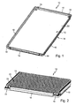
- a collector housing 10 which provides a rear wall 12 and a frame 14.
- the frame 14 is formed from four side walls 16 and two adjacent side walls 16 interconnecting corner connectors 18. All corner connectors 18 are identical. All side walls 16 are formed as hollow chamber profiles which are cut to a corresponding length. Opposite side walls 16 are the same length.
- the rear wall 12 is made of hard foam. Foam material is introduced into the preassembled frame 14 to produce the rear wall 12. Due to the adhesive effect of the foam material, the side walls 16 and the corner connectors 18 are permanently connected to each other by the hardening of the foam material to rigid foam. Overall, this results in a stable composite comprising the four side walls 16, the four corner connectors 18 and the rear wall 12 consisting of hard foam.
- front side 20 of the rear wall 12 may be a metal foil and in particular a Aluminum foil be provided.
- a metal foil in particular a Aluminum foil be provided.
- such a film is not shown in the figures.
- the film completely covers the front side 20 of the rear wall 12.
- a close-meshed protective fabric 24 which may be in particular made of plastic or metal, is provided.
- the protective fabric 24 is preferably fixed to the frame 14 prior to the introduction of the foam material. If the foam material is then introduced into the frame 14, a permanent connection between the rear wall 12 and the protective fabric 24 results.
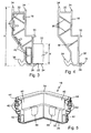
- FIG. 3 which shows a section through a side wall 16 in the region immediately adjacent to a corner connector 18, it becomes clear that the side walls 16 are hollow profiles with cross-sections that are constant over their length.
- the thickness d of the rear wall 12 corresponds to approximately 1/3 of the height h of the side walls 16.
- the height d is in the range of 1/5 to 1/2 of the height h, and more preferably in the range of 1/4 to 1/3.
- an inwardly directed receiving portion 26 for conditioning the protective fabric 24.
- the receiving portion 26 is formed as an inwardly directed web, so that the protective fabric 24 can rest safely.
- the receiving portion 26 may also include a groove 28, in which the protective fabric 24 can be inserted.
- an inwardly directed mounting portion 30 is provided, on which the collector is placed or on which the collector in the housing 10 can be mounted.
- the mounting portion 30 is formed as an inwardly directed shoulder.
- struts 36 are provided in the interior.
- a toothed portion 38 provides.
- the toothed section 38 is formed in particular by elevations extending in the longitudinal direction of the side walls 16 and grooves located between the elevations.
- the corner connectors 18 each have two mutually offset by 90 ° wall sections 40.
- the corner connectors 18 provide the side walls 16 with correspondingly formed receiving sections 26, mounting sections 30 and support sections 34.
- joining portions 42 extending in the longitudinal direction are provided on the free sides of the corner connectors 18.
- the corner connectors 18 can be hidden with the respective side walls 16 in particular releasably in a simple manner with each other.
- skirt portions 44 which, as shown FIG. 6 can be clearly seen, the respective side walls 16 border.
- cover members 48 are provided for closing those openings 46, through which no line pass.
- the cover members 48 can be inserted perpendicular to the plane of the rear wall 12 in the apertures 46.
- guide webs 50 are provided at the openings 46 enclosing areas of the corner connectors.
- the cover parts may have 50 corresponding grooves with the webs.
- the apertures 46 are provided comparatively close to the lower edge of the corner connectors 18, the rear wall 12, or the hard foam forming the rear wall 12, on the inner side in the area adjacent to the apertures 46, formations 52 for the lines to be provided ,
- the side walls 16 are cut to the corresponding predetermined length. Then the side walls 16 are hidden with the corner connectors 18. In this case, the protective fabric 22 is inserted into the frame formed by the side walls 16 and the corner connectors 18. Subsequently, foam material is introduced into the frame 16, in particular under high pressure, to form the rear wall 12. By curing the foam material, a comparatively stable, yet lightweight hard foam back wall is produced.
- the hard foam back wall 12 connects the individual components of the housing 10 inextricably with each other.
- Forming shown may be provided when introducing the foam material in the frame 14 cores, which are removed after foaming or after curing of the foam material.
- the corner connector 18 and the side walls 16 are preferably made of plastic material, wherein the side walls 16 are made by extrusion and the corner connectors 18 by injection molding.
Landscapes
- Engineering & Computer Science (AREA)
- Physics & Mathematics (AREA)
- Life Sciences & Earth Sciences (AREA)
- Sustainable Development (AREA)
- Sustainable Energy (AREA)
- Thermal Sciences (AREA)
- Chemical & Material Sciences (AREA)
- Combustion & Propulsion (AREA)
- Mechanical Engineering (AREA)
- General Engineering & Computer Science (AREA)
- Photovoltaic Devices (AREA)
- Building Environments (AREA)
Applications Claiming Priority (1)
| Application Number | Priority Date | Filing Date | Title |
|---|---|---|---|
| DE102008005856A DE102008005856B4 (de) | 2008-01-17 | 2008-01-17 | Kollektorgehäuse für Solarkollektoren und Verfahren zur Montage eines derartigen Kollektorgehäuses |
Publications (2)
| Publication Number | Publication Date |
|---|---|
| EP2080963A2 true EP2080963A2 (fr) | 2009-07-22 |
| EP2080963A3 EP2080963A3 (fr) | 2011-08-03 |
Family
ID=40545866
Family Applications (1)
| Application Number | Title | Priority Date | Filing Date |
|---|---|---|---|
| EP08021482A Withdrawn EP2080963A3 (fr) | 2008-01-17 | 2008-12-11 | Boîtier de collecteur pour collecteurs solaires et procédé de montage d'un tel boîtier de collecteur |
Country Status (2)
| Country | Link |
|---|---|
| EP (1) | EP2080963A3 (fr) |
| DE (1) | DE102008005856B4 (fr) |
Cited By (3)
| Publication number | Priority date | Publication date | Assignee | Title |
|---|---|---|---|---|
| US20100043781A1 (en) * | 2008-08-21 | 2010-02-25 | Jeremy Jones | Solar panel support module and method of creating array of interchangeable and substitutable solar panel support modules |
| ITAN20100206A1 (it) * | 2010-11-30 | 2012-05-31 | Ariston Thermo Spa | Giunto angolare per collettore solare. |
| AT517654A5 (de) * | 2014-03-10 | 2017-03-15 | Sunlumo Tech Gmbh | Thermischer Sonnenkollektor und Verfahren zur Herstellung eines thermischen Sonnenkollektors |
Families Citing this family (2)
| Publication number | Priority date | Publication date | Assignee | Title |
|---|---|---|---|---|
| DE102010020196B4 (de) | 2010-05-12 | 2012-07-12 | A. Raymond Et Cie | Rahmenvorrichtung für ein Solarmodul sowie Solarmodulanordnung mit Rahmenvorrichtung und Solarmodul |
| DE102011101196B3 (de) * | 2011-05-11 | 2012-08-30 | Klaus Meeh | Solarkollektoranordnung |
Family Cites Families (8)
| Publication number | Priority date | Publication date | Assignee | Title |
|---|---|---|---|---|
| DE2633770A1 (de) * | 1976-07-28 | 1978-02-02 | Sigrid Dipl Ing Reinhard | Wasserdampfdichter solarkollektor |
| DE2712387A1 (de) * | 1977-03-22 | 1978-10-05 | Roth Kg Metallwerk | Sonnenkollektor |
| DE2713628A1 (de) * | 1977-03-28 | 1978-10-05 | Bucher Georg | Formteil, insbesondere traegerelement fuer solar-kollektoren sowie verfahren zur herstellung des formteils |
| DE3611542A1 (de) * | 1986-04-05 | 1987-10-08 | Remscheid Volksbank | Solarmodul |
| DE9007566U1 (de) * | 1990-02-01 | 1992-12-24 | Solvis Energiesysteme GmbH, 3300 Braunschweig | Sonnenkollektor in Flachbauweise |
| ATE186113T1 (de) * | 1995-08-24 | 1999-11-15 | Heinz Groesswang | Sonnenkollektor |
| DE10131465A1 (de) * | 2001-06-29 | 2003-01-09 | Bayer Ag | Solarenergiekollektor |
| DE10321422B4 (de) * | 2003-05-12 | 2005-09-29 | PRIMA Bau- und Dämmsysteme Ges. m.b.H. & Co. KG | Sonnenkollektor |
-
2008
- 2008-01-17 DE DE102008005856A patent/DE102008005856B4/de not_active Expired - Fee Related
- 2008-12-11 EP EP08021482A patent/EP2080963A3/fr not_active Withdrawn
Cited By (6)
| Publication number | Priority date | Publication date | Assignee | Title |
|---|---|---|---|---|
| US20100043781A1 (en) * | 2008-08-21 | 2010-02-25 | Jeremy Jones | Solar panel support module and method of creating array of interchangeable and substitutable solar panel support modules |
| US8371076B2 (en) * | 2008-08-21 | 2013-02-12 | Socore Energy Llc | Solar panel support module and method of creating array of interchangeable and substitutable solar panel support modules |
| ITAN20100206A1 (it) * | 2010-11-30 | 2012-05-31 | Ariston Thermo Spa | Giunto angolare per collettore solare. |
| WO2012073088A3 (fr) * | 2010-11-30 | 2012-09-07 | Ariston Thermo S.P.A. | Joint angulaire pour collecteur solaire |
| AT517654A5 (de) * | 2014-03-10 | 2017-03-15 | Sunlumo Tech Gmbh | Thermischer Sonnenkollektor und Verfahren zur Herstellung eines thermischen Sonnenkollektors |
| AT517654B1 (de) * | 2014-03-10 | 2017-10-15 | Sunlumo Tech Gmbh | Thermischer Sonnenkollektor und Verfahren zur Herstellung eines thermischen Sonnenkollektors |
Also Published As
| Publication number | Publication date |
|---|---|
| DE102008005856A1 (de) | 2009-07-23 |
| DE102008005856B4 (de) | 2010-01-07 |
| EP2080963A3 (fr) | 2011-08-03 |
Similar Documents
| Publication | Publication Date | Title |
|---|---|---|
| EP2318780B1 (fr) | Bâti de module solaire à évacuation d'eau | |
| EP1515587B1 (fr) | Dispositif de chauffage électrique muni d'un élément chauffant scellé | |
| DE2617452A1 (de) | Solarkollektor | |
| DE102012100490A1 (de) | Thermowand und Verfahren zu ihrer Herstellung | |
| DE102016222550A1 (de) | Bodenanordnung für ein temperierbares Batteriegehäuse und Verfahren zu dessen Herstellung | |
| DE102008005856B4 (de) | Kollektorgehäuse für Solarkollektoren und Verfahren zur Montage eines derartigen Kollektorgehäuses | |
| WO2011073319A2 (fr) | Procédé de réalisation d'une armature et armature de pile solaire | |
| DE102019106154A1 (de) | Batteriewanne, Batteriewannenanordnung und Verfahren zur Herstellung einer Batteriewanne | |
| DE102019104647B4 (de) | Batteriehalterung für Fahrzeug | |
| DE102007032155B3 (de) | Mehrschaliges Kunststoffgehäuse | |
| EP1095231B1 (fr) | Procede permettant de fabriquer un capteur solaire | |
| EP3482918A1 (fr) | Procédé de fabrication d'une entretoise d'une pale de rotor d'une éolienne | |
| EP2428137A1 (fr) | Ferrure | |
| DE102012022899A1 (de) | Verbindungselement zur Abstützung eines Stoßfängers eines Kraftfahrzeuges gegenüber einem Montageträger, Baueinheit mit einem solchen Verbindungselement sowie Verfahren zur Herstellung eines Verbindungselements | |
| DE19830345C2 (de) | Verfahren zum Herstellen eines Solarkollektors | |
| DE102005050939B4 (de) | Umhüllung | |
| EP2374666A2 (fr) | Agencement de liaison d'au moins deux composants structurels pour un véhicule automobile et son procédé de fabrication | |
| DE202011000172U1 (de) | Vorrichtung zum Befestigen einer Tragschiene | |
| DE19652568A1 (de) | Solarkollektor mit geteiltem Rahmen | |
| DE102012019351A1 (de) | Verfahren und Positioniereinheit zum Zusammenfügen eines Windenergieanlagentorblatts | |
| EP1669277A1 (fr) | Accessoire de carrosserie véhicule, produit intermédiaire, et son procédé de fabrication | |
| EP1342649B1 (fr) | Pièce de carosserie pour véhicules automobiles et sa méthode de production | |
| DE102019002356A1 (de) | Tragstruktur in Kunststoffbauweise für Schalungspaneel | |
| AT522145B1 (de) | Wagenkastenelement für einen Zugswaggon | |
| EP2880372B1 (fr) | Structure de support pour capteurs solaires et procede a leur manufacture |
Legal Events
| Date | Code | Title | Description |
|---|---|---|---|
| PUAI | Public reference made under article 153(3) epc to a published international application that has entered the european phase |
Free format text: ORIGINAL CODE: 0009012 |
|
| AK | Designated contracting states |
Kind code of ref document: A2 Designated state(s): AT BE BG CH CY CZ DE DK EE ES FI FR GB GR HR HU IE IS IT LI LT LU LV MC MT NL NO PL PT RO SE SI SK TR |
|
| AX | Request for extension of the european patent |
Extension state: AL BA MK RS |
|
| RAP1 | Party data changed (applicant data changed or rights of an application transferred) |
Owner name: JOMA-POLYTEC GMBH |
|
| PUAL | Search report despatched |
Free format text: ORIGINAL CODE: 0009013 |
|
| AK | Designated contracting states |
Kind code of ref document: A3 Designated state(s): AT BE BG CH CY CZ DE DK EE ES FI FR GB GR HR HU IE IS IT LI LT LU LV MC MT NL NO PL PT RO SE SI SK TR |
|
| AX | Request for extension of the european patent |
Extension state: AL BA MK RS |
|
| AKY | No designation fees paid | ||
| REG | Reference to a national code |
Ref country code: DE Ref legal event code: R108 Effective date: 20120411 |
|
| STAA | Information on the status of an ep patent application or granted ep patent |
Free format text: STATUS: THE APPLICATION IS DEEMED TO BE WITHDRAWN |
|
| 18D | Application deemed to be withdrawn |
Effective date: 20120204 |