EP2081009A1 - Vorrichtung zur Korrosionserkennung - Google Patents
Vorrichtung zur Korrosionserkennung Download PDFInfo
- Publication number
- EP2081009A1 EP2081009A1 EP09150884A EP09150884A EP2081009A1 EP 2081009 A1 EP2081009 A1 EP 2081009A1 EP 09150884 A EP09150884 A EP 09150884A EP 09150884 A EP09150884 A EP 09150884A EP 2081009 A1 EP2081009 A1 EP 2081009A1
- Authority
- EP
- European Patent Office
- Prior art keywords
- metal
- proximity sensor
- corrosion
- pellet
- magnetic
- Prior art date
- Legal status (The legal status is an assumption and is not a legal conclusion. Google has not performed a legal analysis and makes no representation as to the accuracy of the status listed.)
- Granted
Links
Images

Classifications
-
- G—PHYSICS
- G01—MEASURING; TESTING
- G01N—INVESTIGATING OR ANALYSING MATERIALS BY DETERMINING THEIR CHEMICAL OR PHYSICAL PROPERTIES
- G01N17/00—Investigating resistance of materials to the weather, to corrosion, or to light
- G01N17/04—Corrosion probes
Definitions
- the present invention relates to a device and a method for detecting the presence of corrosion in a (mainly) metal structure, such as for example a circuit, and due to the presence of a fluid.
- this is the case of domestic hydraulic installations such as central heating installations, individual or collective air-conditioning installations, but also industrial installations such as, for example, chemical installations.
- This phenomenon of corrosion is essentially due to the presence, desired or not, of oxygen in the fluid that circulates or is present in the circuit.
- Various causes can make the action of oxygen possible during the use of these installations, such as in particular sealing leaks or the use of a more or less corrosive fluid. These causes vary over time depending both on the nature of these facilities (internal parameters such as its composition and age), and their conditions. of use (external parameters such as the environment, the temperature, the pressure, the nature of the fluid circulating there).
- Methods for measuring the presence of corrosion may also be physical methods for measuring the electrical resistance of a small section of metal, or indirect measurement methods such as measuring the oxygen concentration, pH, or dissolved metal concentration.
- US 3846795 discloses a stress corrosion cracking detection system, which can occur on special steels, such as stainless steels which are subjected to mechanical stress in a corrosive medium.
- the detector monitors a test piece energized in the corrosive medium and detects the cracking rupture thereof. This type of system is not able to measure generalized corrosion.
- the document US 6843135 describes a generalized corrosion detector, which monitors one or more calibrated coupons without direct access.
- the coupons are designed in such a way that they break when the corrosion has substantially reduced the section.
- the coupons are held under tension by a spring and mechanically connected to a permanent magnet which moves during the breaking of the coupons and thus allows the transmission of a signal outside the corrosive medium.
- the present invention aims to provide a device and a method for detecting and / or measuring corrosion due mainly to the influence of the presence of oxygen in (mainly) metal structures that do not have the disadvantages of state of the art and preferably both very simple and inexpensive.
- the present invention is aimed in particular at providing a device and a method that can be used in any type of installation, preferably in the form of a circuit (closed or open) in which is present a fluid, gas or liquid, possibly potentially corrosive.
- the installation can also be in the form of a tank.
- the main body is preferably intended to be disposed at the periphery of the metal structure (the circuit).
- the main body can be designed to be arranged in the piping and / or inside the metal structure (the circuit).
- the main body comprises a fluid-tight wall.
- the wall is preferably of an electrically insulating nature.
- the wall separates an inner face of the main body from a face external to it.
- the probe is located on the side of the outer face and takes the form of a metal pellet. This pellet is intended to be corroded. Due to corrosion it will decrease in mass.
- the proximity sensor is located on the side of the inner face of the main body.
- the proximity sensor and the probe are separated by the wall.
- the proximity sensor is designed to interact with the metal pellet as long as the mass of the pellet does not decrease below a predetermined amount. This predetermined amount preferably corresponds to a critical corrosion threshold.
- Said main body is thus delimited by the wall which defines the inside and the outside of said main body.
- the probe and the proximity sensor are located on either side of the wall, respectively outside and inside said main body.
- the interaction sensor / proximity sensor is through said wall.
- the probe is constituted by the pellet. This is intended to be immersed in the fluid.
- the wall is also intended to be immersed in the fluid at least partially. All other components of the device are protected from the corrosive fluid by the sealed wall.
- the probe (the pellet) therefore does not include any element designed to move or to move (no mechanical part) and which is intended to be immersed.
- an advantage of the device of the invention is that the proximity sensor interacts directly with the metal pellet.
- the pellet is monitored directly by the sensor.
- the sensor of Proximity is actually designed to detect the loss of mass of the pellet (the probe).
- the devices of the invention are designed for the detection of generalized corrosion, but may also be designed to measure localized corrosion under deposition.
- Deposition corrosion could be monitored by adding a screen in front of the pellet.
- the proximity sensor is designed to activate the signaling and / or alarm means in the absence of proximity sensor / probe interaction.
- the device of the invention comprises means for transmitting the state of the proximity sensor / probe interaction outside the device.
- These means may be said signaling and / or alarm means.
- the period of time between two successive transmissions is preferably at least 12 hours, at least 24 hours, preferably at least 48 hours and preferably at least 100 hours. This limits the power consumption of the device and is especially advantageous when the device must be operated by portable energy sources (batteries, solar energy, etc.) and / or is in a location away from a grid connection.
- the corrosion threshold corresponds to a variation in weight (mass) of the probe (metal pellet) of at least 5%, preferably at least 10%, and preferably at least , 20%, 30%, 40%, 50%.
- the metal pellet is in contact with the wall.
- the probe (the pellet) is directly fixed or secured to the wall.
- the wall is electrically insulating.
- the wall is non-metallic.
- the wall is preferably formed of a polymeric material (plastic).
- the wall of the main body of the device according to the invention comprises at least one component selected from the group consisting of ceramics and non-conductive polymers.
- the devices of the invention allow to have very small dimensions.
- the devices of the invention are preferably equipped with a 1 ⁇ 2 inch, 3 ⁇ 4 inch or 1 inch thread.
- the devices of the invention are alternatively preferably equipped with a thread diameter of between about 10 mm and about 50 mm, preferably between about 15 mm and about 40 mm. This allows them to be mounted on the circuit among a type T connection.
- the probe and the wall can therefore have a dimension that does not exceed the dimensions indicated above.
- the spring is calibrated to present a lower restoring force than the force exerted by the magnet acting on the probe (pellet) as long as said probe does not reach a critical quantity (of its mass) corresponding to a threshold of predetermined corrosion.
- the proximity sensor is of the magnetic type and comprises a magnet, preferably a permanent magnet, and a magnetic contact (switch) or a Hall effect field sensor.
- the probe constitutes a gap or a magnetic path between the magnet and the magnetic contact or the Hall effect field sensor.
- This embodiment is based on the decrease of the magnetic conduction between the magnet and the magnetic switch due to the mass decrease of the probe.
- the Hall effect field sensor requires a probe (pellet) that is magnetic.
- the proximity sensor is of electronic type. This proximity sensor is designed to measure the mass decrease of the probe (pellet). In this embodiment, advantageously, no part moves.
- the proximity sensor can be coupled locally or remotely to the signaling device and / or alarm.
- the signaling and / or alarm means are of the mechanical, electrical, electronic or pneumatic type.
- the thickness of the probe (the pellet) is chosen so as to be at least 5 times lower, preferably at least 10 times lower, and preferably at least 100 times more weak than the thickness of the metal structure to be tested.
- the thickness of the probe is between about 5 ⁇ m and about 100 ⁇ m, preferably between about 25 ⁇ m and about 100 ⁇ m.
- the fluid being present (or circulating) in the metal structure to be controlled may be any liquid or gas.
- the term "corrosive fluid” a liquid or a gas capable of causing the "corrosion” of an object, in this case a metal structure, that is to say the alteration of said object by reaction with oxygen.
- the present invention more particularly relates to the corrosion of metal structures in the form of closed circuits inside which circulates a corrosive fluid.
- the term "potentially corrosive fluid" a liquid or a gas which, under standard conditions of use, is a priori not corrosive, but which is likely to become in particular conditions of use , planned or not.
- an “installation” comprises at least one (or more) structure (s) mainly metallic (s), magnetic (s) or non-magnetic (s), of the same nature or of different natures.
- metallic structure means a structure consisting of at least 50%, preferably at least 60%, preferably at least 70%, preferably at least 80%, preferably at least 90% by weight. of metal (one or more metals of different natures).
- main metal is the metal that is predominantly represented by weight within the installation.
- magnetic metal structure means a structure comprising one or more metals strongly reacting to magnetism.
- magnetic metals are iron, ferric steels, cast iron, nickel and cobalt.
- non-magnetic metal structure means a structure comprising one or more metals reacting weakly or not to magnetism.
- non-magnetic metals are copper, aluminum, lead, stainless and austenitic steel, tin, zinc and brass.
- a metal structure in the sense of the invention is in the form of a closed circuit or open inside which is present (circulates) a fluid that can be more or less corrosive.
- the device and method according to the present invention can therefore be used both for an insulated metal structure or a structure integrated in an installation.
- the detection device is usable for detecting and measuring any type of corrosions (shape, size, etc.), even if it is expected that the signaling and / or alarm means are triggered. only when the corrosion at the tested metal structure is above a certain acceptable threshold, called the "corrosion threshold".
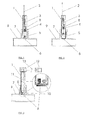
- Figures 1 and 2 represent a device according to a first embodiment respectively in a normal operating situation and in an alarm situation.
- This embodiment is specifically adapted to the detection of corrosion at the level of magnetic metal structures.
- the figures 3 and 4 represent a device according to a second embodiment of the invention respectively in a normal operating situation and in an alarm situation. This embodiment is also adapted specifically to the detection of corrosion at the level of magnetic metal structures.
- the figure 5 represents a third embodiment of the invention adapted to the detection of corrosion at non-magnetic metal structures.
- At least one place for example through a plumbing accessory 9, is placed in one of the forms of execution of the detector device, also called detection device, as described below.
- the figure 1 shows a sectional view of a very simple embodiment of the invention wherein the corrosion detector comprises a main body 1, preferably of synthetic material, delimited by a sealed wall 7 which thus defines the interior and the outside said main body 1, to which correspond respectively an inner face and an outer face.
- a basal end and a distal end are also defined.
- the device according to the invention further comprises a probe, or control sample, preferably taking the form of a metal pellet 6, preferably of small thickness (typically from 5 to 100 ⁇ m, preferably from 25 to 100 ⁇ m).
- This pellet 6 is located near the main body 1, more precisely near (preferably under) the basal end of the main body 1, on the outer side.
- the probe or tablet 6 and the wall 7 of the main body 1 are in contact with each other.
- the metal of the pellet 6 may be of the same nature as the main metal of the installation or one of the metals that constitutes it. In this embodiment, it is essential that the metal is magnetic.
- the spring 3 of the proximity sensor is tared so that below a certain threshold of corrosion, that is to say as long as the metal pellet 6 does not have its mass significantly reduced by corrosion the force of attraction between the magnet 5 and the metal pellet 6 keeps the spring 3 in tension, and makes it visible in the outside of the installation, the green portion of the indicator light 4 through a transparent window 8 made in the side wall of the main body 1.
- the corrosion threshold is preferably at least 5% by weight, preferably at least 10%, and preferably at least 20%, 30%, 40%, 50%, ie that is to say that as long as the metal pellet 6 does not have its reduced mass, because of corrosion, at least 5%, preferably at least 10%, and preferably at least 20%, 30%, 40%, 50% relative to its initial mass, the attractive force between the magnet 5 and the metal pellet 6 keeps the spring 3 in traction, and leaves visible in a visible manner outside the installation, the green portion of the indicator light 4 through a transparent window 8 made in the side wall of the main body 1.
- the corrosion threshold varies according to the type of installation to be tested and the field of application, according to the degree of tolerance compatible with the technical field.
- the detection and / or measurement device furthermore comprises a cocking or reset lever 2 making it possible to position the proximity sensor relatively with respect to the probe 6.
- This lever 2 makes it possible to place initially, since the outside, the magnet 5 in front of the metal chip 6 and put the spring 3 in tension during installation of the device or maintenance.
- the figure 2 shows a sectional view of the same embodiment when the pellet 6 is corroded above a certain threshold and no longer has a sufficient mass to maintain, by magnetic attraction, the magnet 5 against the wall 7.
- the spring 3 returns the indicator 4 upwards and the red portion of the indicator 4 then appears through the transparent window 8, which is thus visible from the outside of the installation.
- the proximity sensor comprises the magnet 5, the magnetic contact 10, and by extension the link 11 and the link 13.
- the predetermined corrosion threshold as indicated above that is to say as long as the mass of the metal pellet 6 is sufficient, to ensure a magnetic path between the magnet 5 and the magnetic contact 10, the latter remains active (closed or open depending on the type of contact used) and the electrical link 11 transmits the information to the signaling and / or alarm device 12.
- the magnetic contact 10 can be replaced by a Hall effect field sensor, well known to those skilled in the art, itself connected to the signaling device and / or alarm 12 by a suitable electronic circuit.
- the proximity sensor therefore comprises a magnet 5, a Hall effect field sensor, and by extension the appropriate electronic circuit.
- the figure 5 shows a preferred embodiment of the invention wherein the magnetic contact 10 is replaced by an electronic proximity sensor or detector.
- the sensor or proximity sensor is of the inductive type and consists of an inductor (coil) 14 connected to a suitable electronic circuit and to the signaling and / or alarm device 12, which may for example be illuminated and / or sound, by an electrical connection 11.
- This device is placed locally or remotely via a link 13.
- This link 13 can be made using any known technique.
- the pellet 6 then acts as a core for this coil 14.
- the sensor transmits the information to the signaling device and / or alarm 12.
- the proximity sensor 14 no longer detects metal objects and communicates the information to the signaling and / or alarm device 12.
- the proximity sensor of the detection device therefore comprises the magnet 5, the coil 14 and by extension the appropriate electronic circuit.
- the inductive proximity sensor 14 may be replaced by a proximity sensor, of optical or capacitive or other type, having the same functions.
- the electronic signal interpretation circuits of the sensor are adapted to signal the absence of metal rather than the presence of metal as would be the case for a metal detector.
- the proximity sensor 10, 14 is advantageously adapted to measure at discrete moments in time.
- the period of time between two successive measurements of the proximity sensor is at least 12 hours, preferably at least 24 hours, at least 48 hours or at least 100 hours.
- the signaling means 12 are advantageously adapted to transmit a signal at discrete moments in time.
- the period of time between two successive transmissions of the signaling device is at least 12 hours, preferably at least 24 hours, at least 48 hours or at least 100 hours.
Landscapes
- Life Sciences & Earth Sciences (AREA)
- Analytical Chemistry (AREA)
- General Health & Medical Sciences (AREA)
- Environmental & Geological Engineering (AREA)
- Environmental Sciences (AREA)
- Physics & Mathematics (AREA)
- Health & Medical Sciences (AREA)
- Ecology (AREA)
- Chemical & Material Sciences (AREA)
- Biochemistry (AREA)
- Biodiversity & Conservation Biology (AREA)
- General Physics & Mathematics (AREA)
- Immunology (AREA)
- Pathology (AREA)
- Testing Resistance To Weather, Investigating Materials By Mechanical Methods (AREA)
- Investigating Or Analyzing Materials By The Use Of Electric Means (AREA)
- Investigating Or Analyzing Materials By The Use Of Magnetic Means (AREA)
Priority Applications (4)
| Application Number | Priority Date | Filing Date | Title |
|---|---|---|---|
| PL09150884T PL2081009T3 (pl) | 2008-01-17 | 2009-01-19 | Urządzenie do wykrywania korozji |
| SI200930018T SI2081009T1 (sl) | 2008-01-17 | 2009-01-19 | Naprava za zaznavanje korozije |
| EP09150884A EP2081009B1 (de) | 2008-01-17 | 2009-01-19 | Vorrichtung zur Korrosionserkennung |
| CY20111100211T CY1111220T1 (el) | 2008-01-17 | 2011-02-22 | Συσκευη για την ανιχνευση διαβρωσης |
Applications Claiming Priority (2)
| Application Number | Priority Date | Filing Date | Title |
|---|---|---|---|
| EP08100573 | 2008-01-17 | ||
| EP09150884A EP2081009B1 (de) | 2008-01-17 | 2009-01-19 | Vorrichtung zur Korrosionserkennung |
Publications (2)
| Publication Number | Publication Date |
|---|---|
| EP2081009A1 true EP2081009A1 (de) | 2009-07-22 |
| EP2081009B1 EP2081009B1 (de) | 2011-01-05 |
Family
ID=40545900
Family Applications (1)
| Application Number | Title | Priority Date | Filing Date |
|---|---|---|---|
| EP09150884A Active EP2081009B1 (de) | 2008-01-17 | 2009-01-19 | Vorrichtung zur Korrosionserkennung |
Country Status (11)
| Country | Link |
|---|---|
| EP (1) | EP2081009B1 (de) |
| AT (1) | ATE494540T1 (de) |
| CY (1) | CY1111220T1 (de) |
| DE (1) | DE602009000503D1 (de) |
| DK (1) | DK2081009T3 (de) |
| ES (1) | ES2356113T3 (de) |
| HR (1) | HRP20110131T1 (de) |
| PL (1) | PL2081009T3 (de) |
| PT (1) | PT2081009E (de) |
| RS (1) | RS51609B (de) |
| SI (1) | SI2081009T1 (de) |
Cited By (3)
| Publication number | Priority date | Publication date | Assignee | Title |
|---|---|---|---|---|
| BE1022558B1 (nl) * | 2015-03-03 | 2016-06-02 | Sercal Belgium Bvba | Component, evenals werkwijze voor het detecteren van de aanwezigheid van één of meerdere in een vloeistofstroom opgeloste stoffen |
| CN106442296A (zh) * | 2016-11-04 | 2017-02-22 | 长沙理工大学 | 一种金属在滨海工业大气中的腐蚀性能模拟加速测试方法及装置 |
| US20180187836A1 (en) * | 2016-12-29 | 2018-07-05 | Paul A. COHEN | Corrosion sensor for storage tank |
Citations (4)
| Publication number | Priority date | Publication date | Assignee | Title |
|---|---|---|---|---|
| US3621810A (en) * | 1970-11-05 | 1971-11-23 | Caterpillar Tractor Co | Corrosion detector |
| US3846795A (en) | 1972-11-03 | 1974-11-05 | Transfer Systems | Early warning material failure indicator |
| US20040055391A1 (en) * | 2002-06-28 | 2004-03-25 | Douglas Dennis G. | Method and apparatus for remotely monitoring corrosion using corrosion coupons |
| EP1411580A1 (de) * | 2002-10-16 | 2004-04-21 | Renault s.a.s. | Vorrichtung zur Feststellung des Korrosionszustandes einer Batterie, insbesondere einer Kraftfahrzeugbatterie |
-
2009
- 2009-01-19 PT PT09150884T patent/PT2081009E/pt unknown
- 2009-01-19 ES ES09150884T patent/ES2356113T3/es active Active
- 2009-01-19 DE DE602009000503T patent/DE602009000503D1/de active Active
- 2009-01-19 PL PL09150884T patent/PL2081009T3/pl unknown
- 2009-01-19 AT AT09150884T patent/ATE494540T1/de active
- 2009-01-19 SI SI200930018T patent/SI2081009T1/sl unknown
- 2009-01-19 EP EP09150884A patent/EP2081009B1/de active Active
- 2009-01-19 DK DK09150884.6T patent/DK2081009T3/da active
- 2009-01-19 RS RS20110059A patent/RS51609B/sr unknown
-
2011
- 2011-02-22 CY CY20111100211T patent/CY1111220T1/el unknown
- 2011-02-23 HR HR20110131T patent/HRP20110131T1/hr unknown
Patent Citations (5)
| Publication number | Priority date | Publication date | Assignee | Title |
|---|---|---|---|---|
| US3621810A (en) * | 1970-11-05 | 1971-11-23 | Caterpillar Tractor Co | Corrosion detector |
| US3846795A (en) | 1972-11-03 | 1974-11-05 | Transfer Systems | Early warning material failure indicator |
| US20040055391A1 (en) * | 2002-06-28 | 2004-03-25 | Douglas Dennis G. | Method and apparatus for remotely monitoring corrosion using corrosion coupons |
| US6843135B2 (en) | 2002-06-28 | 2005-01-18 | Vista Engineering Technologies Llc | Method and apparatus for remotely monitoring corrosion using corrosion coupons |
| EP1411580A1 (de) * | 2002-10-16 | 2004-04-21 | Renault s.a.s. | Vorrichtung zur Feststellung des Korrosionszustandes einer Batterie, insbesondere einer Kraftfahrzeugbatterie |
Cited By (7)
| Publication number | Priority date | Publication date | Assignee | Title |
|---|---|---|---|---|
| BE1022558B1 (nl) * | 2015-03-03 | 2016-06-02 | Sercal Belgium Bvba | Component, evenals werkwijze voor het detecteren van de aanwezigheid van één of meerdere in een vloeistofstroom opgeloste stoffen |
| WO2016139563A1 (en) * | 2015-03-03 | 2016-09-09 | Sercal Belgium Bvba | Component as well as a method for detecting the presence of one or several solutes in a liquid stream |
| CN106442296A (zh) * | 2016-11-04 | 2017-02-22 | 长沙理工大学 | 一种金属在滨海工业大气中的腐蚀性能模拟加速测试方法及装置 |
| US20180187836A1 (en) * | 2016-12-29 | 2018-07-05 | Paul A. COHEN | Corrosion sensor for storage tank |
| US10781974B2 (en) * | 2016-12-29 | 2020-09-22 | Paul A. COHEN | Corrosion sensor for storage tank |
| US20200408361A1 (en) * | 2016-12-29 | 2020-12-31 | Paul A. COHEN | Corrosion sensor for storage tank |
| US11739883B2 (en) * | 2016-12-29 | 2023-08-29 | Paul A. COHEN | Corrosion sensor for storage tank |
Also Published As
| Publication number | Publication date |
|---|---|
| PT2081009E (pt) | 2011-02-10 |
| DK2081009T3 (da) | 2011-03-21 |
| DE602009000503D1 (de) | 2011-02-17 |
| CY1111220T1 (el) | 2015-06-11 |
| SI2081009T1 (sl) | 2011-05-31 |
| HRP20110131T1 (hr) | 2011-03-31 |
| PL2081009T3 (pl) | 2011-05-31 |
| ATE494540T1 (de) | 2011-01-15 |
| EP2081009B1 (de) | 2011-01-05 |
| RS51609B (sr) | 2011-08-31 |
| ES2356113T3 (es) | 2011-04-05 |
Similar Documents
| Publication | Publication Date | Title |
|---|---|---|
| EP2081009B1 (de) | Vorrichtung zur Korrosionserkennung | |
| FR2977667A1 (fr) | Module de surveillance d'au moins une grandeur physique caracteristique de l'etat d'un organe de guidage par contact | |
| FR2702584A1 (fr) | Dispositif de contrôle. | |
| EP2166317A1 (de) | Steuereinrichtung einer Pumpe zum Hochpumpen von Kondensat | |
| EP0597078B1 (de) | Vorrichtung zum selektiven nachweis von gasen | |
| FR2893406A1 (fr) | Sonde de mesure,en particulier pour un dispositif de mesure de l'epaisseur de couches minces. | |
| FR2776772A1 (fr) | Procede et dispositif de mesure de la pression d'un fluide et utilisation du dispositif | |
| US11913892B2 (en) | Condensation detection element | |
| US5594162A (en) | Valve stem gas leak detector | |
| JP2006317196A (ja) | 水素ガスセンサ | |
| GB2480760A (en) | Method and apparatus for corrosion monitoring | |
| EP2200055B1 (de) | Elektrischer Schalter mit optimiertem Betrieb | |
| US6823751B1 (en) | Sphere or pig detection switch assembly | |
| FR3075970A1 (fr) | Dispositif de verification de l’integrite d’un systeme de detection de court-circuit | |
| FR2713778A1 (fr) | Appareil de détection de pollution des milieux aquatiques. | |
| EP3754319B1 (de) | Irreversibler anzeiger von druckveränderungen | |
| FR2750765A1 (fr) | Detecteur de liquide dans un element d'une installation et son utilisation pour la detection de fuites | |
| FR2977666A1 (fr) | Module de surveillance d'au moins une grandeur physique caracteristique de l'etat d'un organe de guidage par contact, alimente par un generateur thermoelectrique | |
| EP1319936B1 (de) | Druckdetektor | |
| EP1265055A1 (de) | Betrugsfeststellungsvorrichtung für einen Flüssigkeitszähler | |
| WO2013004948A1 (fr) | Boite de pallier instrumentee avec un capteur d'emission acoustique | |
| WO2004044541A1 (fr) | Dispositif de mesure d'un flux thermique | |
| WO2023001922A1 (fr) | Detecteur de pression de fluide | |
| FR3104708A1 (fr) | Capteur de niveau de liquide du type analogique | |
| EP1411580B1 (de) | Vorrichtung zur Feststellung des Korrosionszustandes einer Batterie, insbesondere einer Kraftfahrzeugbatterie |
Legal Events
| Date | Code | Title | Description |
|---|---|---|---|
| PUAI | Public reference made under article 153(3) epc to a published international application that has entered the european phase |
Free format text: ORIGINAL CODE: 0009012 |
|
| AK | Designated contracting states |
Kind code of ref document: A1 Designated state(s): AT BE BG CH CY CZ DE DK EE ES FI FR GB GR HR HU IE IS IT LI LT LU LV MC MK MT NL NO PL PT RO SE SI SK TR |
|
| AX | Request for extension of the european patent |
Extension state: AL BA RS |
|
| RTI1 | Title (correction) |
Free format text: APPARATUS FOR CORROSION DETECTION |
|
| 17P | Request for examination filed |
Effective date: 20100114 |
|
| AKX | Designation fees paid |
Designated state(s): AT BE BG CH CY CZ DE DK EE ES FI FR GB GR HR HU IE IS IT LI LT LU LV MC MK MT NL NO PL PT RO SE SI SK TR |
|
| AXX | Extension fees paid |
Extension state: RS Payment date: 20100114 Extension state: BA Payment date: 20100114 Extension state: AL Payment date: 20100114 |
|
| GRAP | Despatch of communication of intention to grant a patent |
Free format text: ORIGINAL CODE: EPIDOSNIGR1 |
|
| RIC1 | Information provided on ipc code assigned before grant |
Ipc: G01N 17/04 20060101ALI20100615BHEP Ipc: G01N 17/00 20060101AFI20100615BHEP |
|
| GRAS | Grant fee paid |
Free format text: ORIGINAL CODE: EPIDOSNIGR3 |
|
| GRAA | (expected) grant |
Free format text: ORIGINAL CODE: 0009210 |
|
| AK | Designated contracting states |
Kind code of ref document: B1 Designated state(s): AT BE BG CH CY CZ DE DK EE ES FI FR GB GR HR HU IE IS IT LI LT LU LV MC MK MT NL NO PL PT RO SE SI SK TR |
|
| AX | Request for extension of the european patent |
Extension state: AL BA RS |
|
| REG | Reference to a national code |
Ref country code: GB Ref legal event code: FG4D |
|
| REG | Reference to a national code |
Ref country code: CH Ref legal event code: EP |
|
| REG | Reference to a national code |
Ref country code: IE Ref legal event code: FG4D Free format text: LANGUAGE OF EP DOCUMENT: FRENCH |
|
| REG | Reference to a national code |
Ref country code: PT Ref legal event code: SC4A Free format text: AVAILABILITY OF NATIONAL TRANSLATION Effective date: 20110203 |
|
| REF | Corresponds to: |
Ref document number: 602009000503 Country of ref document: DE Date of ref document: 20110217 Kind code of ref document: P |
|
| REG | Reference to a national code |
Ref country code: DE Ref legal event code: R096 Ref document number: 602009000503 Country of ref document: DE Effective date: 20110217 |
|
| REG | Reference to a national code |
Ref country code: HR Ref legal event code: TUEP Ref document number: P20110131 Country of ref document: HR |
|
| REG | Reference to a national code |
Ref country code: RO Ref legal event code: EPE |
|
| REG | Reference to a national code |
Ref country code: CH Ref legal event code: NV Representative=s name: CRONIN INTELLECTUAL PROPERTY |
|
| REG | Reference to a national code |
Ref country code: DK Ref legal event code: T3 |
|
| REG | Reference to a national code |
Ref country code: NL Ref legal event code: T3 |
|
| REG | Reference to a national code |
Ref country code: SE Ref legal event code: TRGR |
|
| REG | Reference to a national code |
Ref country code: HR Ref legal event code: T1PR Ref document number: P20110131 Country of ref document: HR |
|
| REG | Reference to a national code |
Ref country code: ES Ref legal event code: FG2A Ref document number: 2356113 Country of ref document: ES Kind code of ref document: T3 Effective date: 20110405 |
|
| REG | Reference to a national code |
Ref country code: NO Ref legal event code: T2 Effective date: 20110105 |
|
| REG | Reference to a national code |
Ref country code: GR Ref legal event code: EP Ref document number: 20110400503 Country of ref document: GR Effective date: 20110412 |
|
| REG | Reference to a national code |
Ref country code: PL Ref legal event code: T3 |
|
| REG | Reference to a national code |
Ref country code: SK Ref legal event code: T3 Ref document number: E 9002 Country of ref document: SK |
|
| REG | Reference to a national code |
Ref country code: HU Ref legal event code: AG4A Ref document number: E010845 Country of ref document: HU |
|
| PLBE | No opposition filed within time limit |
Free format text: ORIGINAL CODE: 0009261 |
|
| STAA | Information on the status of an ep patent application or granted ep patent |
Free format text: STATUS: NO OPPOSITION FILED WITHIN TIME LIMIT |
|
| 26N | No opposition filed |
Effective date: 20111006 |
|
| REG | Reference to a national code |
Ref country code: DE Ref legal event code: R097 Ref document number: 602009000503 Country of ref document: DE Effective date: 20111006 |
|
| REG | Reference to a national code |
Ref country code: FR Ref legal event code: PLFP Year of fee payment: 8 |
|
| REG | Reference to a national code |
Ref country code: FR Ref legal event code: PLFP Year of fee payment: 9 |
|
| REG | Reference to a national code |
Ref country code: FR Ref legal event code: PLFP Year of fee payment: 10 |
|
| PGFP | Annual fee paid to national office [announced via postgrant information from national office to epo] |
Ref country code: BG Payment date: 20171219 Year of fee payment: 10 |
|
| PGFP | Annual fee paid to national office [announced via postgrant information from national office to epo] |
Ref country code: CY Payment date: 20171218 Year of fee payment: 10 Ref country code: RO Payment date: 20180109 Year of fee payment: 10 |
|
| REG | Reference to a national code |
Ref country code: CH Ref legal event code: PCAR Free format text: NEW ADDRESS: CHEMIN DE LA VUARPILLIERE 29, 1260 NYON (CH) |
|
| PGFP | Annual fee paid to national office [announced via postgrant information from national office to epo] |
Ref country code: MT Payment date: 20171221 Year of fee payment: 10 |
|
| REG | Reference to a national code |
Ref country code: HR Ref legal event code: ODRP Ref document number: P20110131 Country of ref document: HR Payment date: 20181218 Year of fee payment: 11 |
|
| PG25 | Lapsed in a contracting state [announced via postgrant information from national office to epo] |
Ref country code: CY Free format text: LAPSE BECAUSE OF NON-PAYMENT OF DUE FEES Effective date: 20190119 Ref country code: RO Free format text: LAPSE BECAUSE OF NON-PAYMENT OF DUE FEES Effective date: 20190119 |
|
| PG25 | Lapsed in a contracting state [announced via postgrant information from national office to epo] |
Ref country code: BG Free format text: LAPSE BECAUSE OF NON-PAYMENT OF DUE FEES Effective date: 20190731 |
|
| REG | Reference to a national code |
Ref country code: HR Ref legal event code: ODRP Ref document number: P20110131 Country of ref document: HR Payment date: 20191218 Year of fee payment: 12 |
|
| PGFP | Annual fee paid to national office [announced via postgrant information from national office to epo] |
Ref country code: PT Payment date: 20191218 Year of fee payment: 12 Ref country code: SK Payment date: 20191219 Year of fee payment: 12 Ref country code: LT Payment date: 20191218 Year of fee payment: 12 Ref country code: CZ Payment date: 20191223 Year of fee payment: 12 Ref country code: MC Payment date: 20191224 Year of fee payment: 12 |
|
| PGFP | Annual fee paid to national office [announced via postgrant information from national office to epo] |
Ref country code: LV Payment date: 20191218 Year of fee payment: 12 Ref country code: IS Payment date: 20191218 Year of fee payment: 12 Ref country code: HR Payment date: 20191218 Year of fee payment: 12 Ref country code: EE Payment date: 20191218 Year of fee payment: 12 Ref country code: GR Payment date: 20191223 Year of fee payment: 12 |
|
| PGFP | Annual fee paid to national office [announced via postgrant information from national office to epo] |
Ref country code: HU Payment date: 20200124 Year of fee payment: 12 Ref country code: ES Payment date: 20200203 Year of fee payment: 12 |
|
| PGFP | Annual fee paid to national office [announced via postgrant information from national office to epo] |
Ref country code: SI Payment date: 20200106 Year of fee payment: 12 |
|
| PGFP | Annual fee paid to national office [announced via postgrant information from national office to epo] |
Ref country code: MK Payment date: 20191218 Year of fee payment: 12 |
|
| PGFP | Annual fee paid to national office [announced via postgrant information from national office to epo] |
Ref country code: FI Payment date: 20201221 Year of fee payment: 13 Ref country code: SE Payment date: 20201223 Year of fee payment: 13 Ref country code: DK Payment date: 20201221 Year of fee payment: 13 Ref country code: NO Payment date: 20201221 Year of fee payment: 13 Ref country code: IE Payment date: 20201221 Year of fee payment: 13 |
|
| PGFP | Annual fee paid to national office [announced via postgrant information from national office to epo] |
Ref country code: PL Payment date: 20201218 Year of fee payment: 13 |
|
| PGFP | Annual fee paid to national office [announced via postgrant information from national office to epo] |
Ref country code: IT Payment date: 20210104 Year of fee payment: 13 |
|
| PGFP | Annual fee paid to national office [announced via postgrant information from national office to epo] |
Ref country code: TR Payment date: 20210108 Year of fee payment: 13 |
|
| REG | Reference to a national code |
Ref country code: HR Ref legal event code: PBON Ref document number: P20110131 Country of ref document: HR Effective date: 20210119 |
|
| REG | Reference to a national code |
Ref country code: EE Ref legal event code: MM4A Ref document number: E005374 Country of ref document: EE Effective date: 20210131 |
|
| PG25 | Lapsed in a contracting state [announced via postgrant information from national office to epo] |
Ref country code: MC Free format text: LAPSE BECAUSE OF NON-PAYMENT OF DUE FEES Effective date: 20210201 |
|
| REG | Reference to a national code |
Ref country code: SK Ref legal event code: MM4A Ref document number: E 9002 Country of ref document: SK Effective date: 20210119 |
|
| REG | Reference to a national code |
Ref country code: LT Ref legal event code: MM4D Effective date: 20210119 |
|
| PG25 | Lapsed in a contracting state [announced via postgrant information from national office to epo] |
Ref country code: HR Free format text: LAPSE BECAUSE OF NON-PAYMENT OF DUE FEES Effective date: 20210119 Ref country code: HU Free format text: LAPSE BECAUSE OF NON-PAYMENT OF DUE FEES Effective date: 20210120 Ref country code: CZ Free format text: LAPSE BECAUSE OF NON-PAYMENT OF DUE FEES Effective date: 20210119 Ref country code: EE Free format text: LAPSE BECAUSE OF NON-PAYMENT OF DUE FEES Effective date: 20210131 |
|
| PG25 | Lapsed in a contracting state [announced via postgrant information from national office to epo] |
Ref country code: LV Free format text: LAPSE BECAUSE OF NON-PAYMENT OF DUE FEES Effective date: 20210119 Ref country code: GR Free format text: LAPSE BECAUSE OF NON-PAYMENT OF DUE FEES Effective date: 20210805 Ref country code: PT Free format text: LAPSE BECAUSE OF NON-PAYMENT OF DUE FEES Effective date: 20210719 Ref country code: SK Free format text: LAPSE BECAUSE OF NON-PAYMENT OF DUE FEES Effective date: 20210119 |
|
| PG25 | Lapsed in a contracting state [announced via postgrant information from national office to epo] |
Ref country code: LT Free format text: LAPSE BECAUSE OF NON-PAYMENT OF DUE FEES Effective date: 20210119 Ref country code: MT Free format text: LAPSE BECAUSE OF FAILURE TO SUBMIT A TRANSLATION OF THE DESCRIPTION OR TO PAY THE FEE WITHIN THE PRESCRIBED TIME-LIMIT Effective date: 20190119 |
|
| REG | Reference to a national code |
Ref country code: SI Ref legal event code: KO00 Effective date: 20211129 |
|
| PG25 | Lapsed in a contracting state [announced via postgrant information from national office to epo] |
Ref country code: SI Free format text: LAPSE BECAUSE OF NON-PAYMENT OF DUE FEES Effective date: 20210120 |
|
| REG | Reference to a national code |
Ref country code: ES Ref legal event code: FD2A Effective date: 20220422 |
|
| PG25 | Lapsed in a contracting state [announced via postgrant information from national office to epo] |
Ref country code: ES Free format text: LAPSE BECAUSE OF NON-PAYMENT OF DUE FEES Effective date: 20210120 |
|
| REG | Reference to a national code |
Ref country code: FI Ref legal event code: MAE |
|
| REG | Reference to a national code |
Ref country code: NO Ref legal event code: MMEP Ref country code: DK Ref legal event code: EBP Effective date: 20220131 |
|
| REG | Reference to a national code |
Ref country code: SE Ref legal event code: EUG |
|
| PG25 | Lapsed in a contracting state [announced via postgrant information from national office to epo] |
Ref country code: SE Free format text: LAPSE BECAUSE OF NON-PAYMENT OF DUE FEES Effective date: 20220120 Ref country code: NO Free format text: LAPSE BECAUSE OF NON-PAYMENT OF DUE FEES Effective date: 20220131 Ref country code: FI Free format text: LAPSE BECAUSE OF NON-PAYMENT OF DUE FEES Effective date: 20220119 |
|
| PG25 | Lapsed in a contracting state [announced via postgrant information from national office to epo] |
Ref country code: IT Free format text: LAPSE BECAUSE OF NON-PAYMENT OF DUE FEES Effective date: 20220119 Ref country code: IE Free format text: LAPSE BECAUSE OF NON-PAYMENT OF DUE FEES Effective date: 20220119 Ref country code: DK Free format text: LAPSE BECAUSE OF NON-PAYMENT OF DUE FEES Effective date: 20220131 |
|
| PG25 | Lapsed in a contracting state [announced via postgrant information from national office to epo] |
Ref country code: PL Free format text: LAPSE BECAUSE OF NON-PAYMENT OF DUE FEES Effective date: 20220119 |
|
| PG25 | Lapsed in a contracting state [announced via postgrant information from national office to epo] |
Ref country code: TR Free format text: LAPSE BECAUSE OF NON-PAYMENT OF DUE FEES Effective date: 20220119 |
|
| PG25 | Lapsed in a contracting state [announced via postgrant information from national office to epo] |
Ref country code: IS Free format text: LAPSE BECAUSE OF NON-PAYMENT OF DUE FEES Effective date: 20210803 |
|
| PGFP | Annual fee paid to national office [announced via postgrant information from national office to epo] |
Ref country code: GB Payment date: 20251220 Year of fee payment: 18 |
|
| PGFP | Annual fee paid to national office [announced via postgrant information from national office to epo] |
Ref country code: LU Payment date: 20251217 Year of fee payment: 18 Ref country code: NL Payment date: 20251217 Year of fee payment: 18 Ref country code: FR Payment date: 20251217 Year of fee payment: 18 |
|
| PGFP | Annual fee paid to national office [announced via postgrant information from national office to epo] |
Ref country code: BE Payment date: 20251217 Year of fee payment: 18 |
|
| REG | Reference to a national code |
Ref country code: CH Ref legal event code: U11 Free format text: ST27 STATUS EVENT CODE: U-0-0-U10-U11 (AS PROVIDED BY THE NATIONAL OFFICE) Effective date: 20260201 |
|
| PGFP | Annual fee paid to national office [announced via postgrant information from national office to epo] |
Ref country code: DE Payment date: 20251217 Year of fee payment: 18 |
|
| PGFP | Annual fee paid to national office [announced via postgrant information from national office to epo] |
Ref country code: AT Payment date: 20251218 Year of fee payment: 18 |
|
| PGFP | Annual fee paid to national office [announced via postgrant information from national office to epo] |
Ref country code: CH Payment date: 20260201 Year of fee payment: 18 |