EP2081054A2 - Procédé pour la séparation de champ d'ondes en données 3D de flûte remorquée à double capteur avec énergie dénaturée dans la direction transverse au remorquage - Google Patents
Procédé pour la séparation de champ d'ondes en données 3D de flûte remorquée à double capteur avec énergie dénaturée dans la direction transverse au remorquage Download PDFInfo
- Publication number
- EP2081054A2 EP2081054A2 EP09150793A EP09150793A EP2081054A2 EP 2081054 A2 EP2081054 A2 EP 2081054A2 EP 09150793 A EP09150793 A EP 09150793A EP 09150793 A EP09150793 A EP 09150793A EP 2081054 A2 EP2081054 A2 EP 2081054A2
- Authority
- EP
- European Patent Office
- Prior art keywords
- streamer
- wavenumber
- particle velocity
- records
- spectrum
- Prior art date
- Legal status (The legal status is an assumption and is not a legal conclusion. Google has not performed a legal analysis and makes no representation as to the accuracy of the status listed.)
- Withdrawn
Links
- 230000009977 dual effect Effects 0.000 title claims abstract description 14
- 238000000034 method Methods 0.000 title claims description 68
- 238000000926 separation method Methods 0.000 title description 13
- 238000001228 spectrum Methods 0.000 claims abstract description 75
- 239000002245 particle Substances 0.000 claims abstract description 65
- 230000001131 transforming effect Effects 0.000 claims description 7
- 239000013598 vector Substances 0.000 claims description 2
- 238000012545 processing Methods 0.000 description 26
- 230000008569 process Effects 0.000 description 11
- XLYOFNOQVPJJNP-UHFFFAOYSA-N water Substances O XLYOFNOQVPJJNP-UHFFFAOYSA-N 0.000 description 10
- 230000015572 biosynthetic process Effects 0.000 description 5
- 238000005755 formation reaction Methods 0.000 description 5
- 239000003208 petroleum Substances 0.000 description 5
- 238000010586 diagram Methods 0.000 description 4
- 230000035508 accumulation Effects 0.000 description 3
- 238000009825 accumulation Methods 0.000 description 3
- 238000003491 array Methods 0.000 description 3
- 238000010606 normalization Methods 0.000 description 3
- 230000003595 spectral effect Effects 0.000 description 3
- 239000004215 Carbon black (E152) Substances 0.000 description 2
- 230000001133 acceleration Effects 0.000 description 2
- 230000000694 effects Effects 0.000 description 2
- 239000002360 explosive Substances 0.000 description 2
- 229930195733 hydrocarbon Natural products 0.000 description 2
- 150000002430 hydrocarbons Chemical class 0.000 description 2
- VNWKTOKETHGBQD-UHFFFAOYSA-N methane Chemical compound C VNWKTOKETHGBQD-UHFFFAOYSA-N 0.000 description 2
- 238000012986 modification Methods 0.000 description 2
- 230000004048 modification Effects 0.000 description 2
- 240000001973 Ficus microcarpa Species 0.000 description 1
- 238000004458 analytical method Methods 0.000 description 1
- 238000013459 approach Methods 0.000 description 1
- 230000008859 change Effects 0.000 description 1
- 125000004122 cyclic group Chemical group 0.000 description 1
- 238000005553 drilling Methods 0.000 description 1
- 238000010891 electric arc Methods 0.000 description 1
- 238000010892 electric spark Methods 0.000 description 1
- 238000011156 evaluation Methods 0.000 description 1
- 239000007789 gas Substances 0.000 description 1
- 229910052500 inorganic mineral Inorganic materials 0.000 description 1
- 239000011707 mineral Substances 0.000 description 1
- 239000003345 natural gas Substances 0.000 description 1
- 230000003287 optical effect Effects 0.000 description 1
- 230000002093 peripheral effect Effects 0.000 description 1
- 230000001902 propagating effect Effects 0.000 description 1
- 230000009467 reduction Effects 0.000 description 1
- 239000011435 rock Substances 0.000 description 1
- 230000009466 transformation Effects 0.000 description 1
Images


Classifications
-
- G—PHYSICS
- G01—MEASURING; TESTING
- G01V—GEOPHYSICS; GRAVITATIONAL MEASUREMENTS; DETECTING MASSES OR OBJECTS; TAGS
- G01V1/00—Seismology; Seismic or acoustic prospecting or detecting
- G01V1/28—Processing seismic data, e.g. for interpretation or for event detection
- G01V1/36—Effecting static or dynamic corrections on records, e.g. correcting spread; Correlating seismic signals; Eliminating effects of unwanted energy
-
- G—PHYSICS
- G01—MEASURING; TESTING
- G01V—GEOPHYSICS; GRAVITATIONAL MEASUREMENTS; DETECTING MASSES OR OBJECTS; TAGS
- G01V2210/00—Details of seismic processing or analysis
- G01V2210/50—Corrections or adjustments related to wave propagation
- G01V2210/56—De-ghosting; Reverberation compensation
Definitions
- This invention relates generally to the field of geophysical prospecting. More particularly, the invention relates to the field of marine seismic data processing.
- geophysical prospecting is commonly used to aid in the search for and evaluation of subterranean formations.
- Geophysical prospecting techniques yield knowledge of the subsurface structure of the earth, which is useful for finding and extracting valuable mineral resources, particularly hydrocarbon deposits such as oil and natural gas.
- a well-known technique of geophysical prospecting is a seismic survey.
- a seismic signal is generated on or near the earth's surface which then travels downward into the subsurface of the earth.
- the seismic signal may also travel downward through a body of water overlying the subsurface of the earth.
- Seismic energy sources are used to generate the seismic signal which, after propagating into the earth, is at least partially reflected by subsurface seismic reflectors.
- Such seismic reflectors typically are interfaces between subterranean formations having different elastic properties, specifically sound wave velocity and rock density, which lead to differences in acoustic impedance at the interfaces.
- the reflected seismic energy is detected by seismic sensors (also called seismic receivers) at or near the surface of the earth, in an overlying body of water, or at known depths in boreholes and recorded.
- the appropriate seismic sources for generating the seismic signal in land seismic surveys may include explosives or vibrators.
- Marine seismic surveys typically employ a submerged seismic source towed by a ship and periodically activated to generate an acoustic wavefield.
- the seismic source generating the wavefield may be of several types, including a small explosive charge, an electric spark or arc, a marine vibrator, and, typically, a gun.
- the seismic source gun may be a water gun, a vapor gun, and, most typically, an air gun.
- a marine seismic source consists not of a single source element, but of a spatially-distributed array of source elements. This arrangement is particularly true for air guns, currently the most common form of marine seismic source.
- seismic sensors typically include particle velocity sensors, particularly in land surveys, and water pressure sensors (typically water pressure gradient sensors), particularly in marine surveys.
- particle acceleration sensors are used in place of or in addition to particle velocity sensors.
- Particle velocity sensors and water pressure sensors are commonly known in the art as geophones and hydrophones, respectively.
- Seismic sensors may be deployed by themselves, but are more commonly deployed in sensor arrays. Additionally, pressure sensors and particle velocity sensors may be deployed together in a marine survey, collocated in pairs or pairs of arrays.
- a seismic survey vessel travels on the water surface, typically at about 5 knots, and contains seismic acquisition equipment, such as navigation control, seismic source control, seismic sensor control, and recording equipment.
- the seismic source control equipment causes a seismic source towed in the body of water by the seismic vessel to actuate at selected times.
- Seismic streamers also called seismic cables, are elongate cable-like structures towed in the body of water by the seismic survey vessel that tows the seismic source or by another seismic survey ship.
- a plurality of seismic streamers are towed behind a seismic vessel.
- the seismic streamers contain sensors to detect the reflected wavefields initiated by the seismic source and reflected from reflecting interfaces.
- the seismic streamers contain pressure sensors such as hydrophones, but seismic streamers have been proposed that contain water particle velocity sensors such as geophones or particle acceleration sensors such as accelerometers, in addition to hydrophones.
- the pressure sensors and particle motion sensors may be deployed in close proximity, collocated in pairs or pairs of arrays along a seismic cable.
- the resulting seismic data obtained in performing the survey is processed to yield information relating to the geologic structure and properties of the subterranean formations in the area being surveyed.
- the processed seismic data is processed for display and analysis of potential hydrocarbon content of these subterranean formations.
- the goal of seismic data processing is to extract from the seismic data as much information as possible regarding the subterranean formations in order to adequately image the geologic subsurface.
- large sums of money are expended in gathering, processing, and interpreting seismic data.
- the process of constructing the reflector surfaces defining the subterranean earth layers of interest from the recorded seismic data provides an image of the earth in depth or time.
- the image of the structure of the Earth's subsurface is produced in order to enable an interpreter to select locations with the greatest probability of having petroleum accumulations.
- a well To verify the presence of petroleum, a well must be drilled. Drilling wells to determine whether petroleum deposits are present or not, is an extremely expensive and time-consuming undertaking. For that reason, there is a continuing need to improve the processing and display of the seismic data, so as to produce an image of the structure of the Earth's subsurface that will improve the ability of an interpreter, whether the interpretation is made by a computer or a human, to assess the probability that an accumulation of petroleum exists at a particular location in the Earth's subsurface.
- Dual sensor towed streamer reflection seismic data consist of pressure field and vertical particle velocity field records.
- a central element in the processing chain of seismic data is its separation into records containing only the upgoing and downgoing components of the pressure wavefields. This separation can be performed after transforming the data into the frequency-wavenumber ( f-k x -k y ) domain, taking both the difference between and the sum of, respectively the frequency-wavenumber spectrum of the pressure record and a scaled version of the frequency-wavenumber spectrum of the vertical particle velocity record, and dividing the resulting spectra by two.
- non-evanescent energy For non-evanescent energy, it is scaled in the frequency-wavenumber domain by a real filter which systematically increases with increasing wavenumber for a given frequency.
- spatial aliasing in the cross-streamer direction is all too common in marine seismic surveys.
- The, in the case of cross-streamer aliasing, energy is wrapped to a lower cross-streamer wavenumber k y . Subsequently, if these wrap-around effects in the wavenumber are not taken into account, then the scaling filter is computed from the wrong wavenumber, one that is too low.
- the aliased energy in the vertical particle velocity record (or alternatively, the pressure record) is scaled by filter coefficients that are consistently too low (or too high, respectively).
- the superposition of upgoing and downgoing wavefield components in the original records causes a specific pattern of receiver ghost notches in the corresponding frequency-wavenumber spectra.
- the recorded energy is cancelled at a specific frequency-wavenumber combination in, for example, the spectrum of the pressure field, the corresponding recorded energy is maximal in the spectrum of the vertical particle velocity.
- this correspondence causes an incorrect separation of the upgoing and downgoing wavefield components at the notches in the frequency wavenumber spectrum of the pressure record (or, alternatively, the vertical particle velocity record).
- the aliased energy is incorrectly scaled for the vertical particle velocity record (or alternatively, the pressure record), so that the resulting separated wavefield components are incorrectly computed.
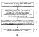
- the invention is a method for separating upgoing and downgoing wavefield components in 3D dual sensor towed streamer data, which may have aliased energy in the cross-streamer direction.
- Pressure records and vertical particle velocity records from the streamer data are transformed to the inline wavenumber domain.
- a series of scaling filters are applied to the transformed vertical particle velocity records at each inline wavenumber, wherein each of the series of scaling filters is calculated for a different cross-streamer wavenumber range and in blocks of inline traces in which all seismic events are approximately linear.
- the pressure spectrum and the scaled vertical particle velocity spectrum are combined to separate upgoing and downgoing wavefield components.
- the separated upgoing and downgoing wavefield components are inverse-transformed back to the time-space domain.
- FIG. 1 is a flowchart illustrating the processing steps of a first embodiment of the method of the invention for separating upgoing and downgoing wavefield components in 3D dual sensor towed streamer data;
- FIG. 2 is a flowchart illustrating the initial processing steps of a second embodiment of the method of the invention for separating upgoing and downgoing wavefield components in 3D dual sensor towed streamer data;
- FIG. 3 is a flowchart illustrating the intermediate processing steps of an embodiment of the invention for processing windows from FIG. 2 ;
- FIG. 4 is a flowchart illustrating the intermediate processing steps of an embodiment of the invention for processing spectral ratios from FIG. 3 .
- FIG. 5 is a flowchart illustrating the final processing steps of the second embodiment of the invention for separating upgoing and downgoing wavefield components in 3D dual sensor towed streamer data, as shown in FIGS. 1-4 ;
- FIG. 6 shows a diagram illustrating an example third panel as used in the method of the invention.
- FIG. 7 shows a diagram illustrating masks created from the stripes in the example third panel in FIG. 6 ;
- FIG. 8 shows a graph of the amplitude spectra of the reference trace compared with the results of the method of the invention for different maximum dealiasing orders L ;
- FIG. 9 shows a graph of the amplitude spectra of the reference trace compared with more results of the method of the invention for different maximum dealiasing orders L ;
- the vertical particle velocity record Before the vertical particle velocity record can be correctly scaled for wavefield separation, its spectrum needs to be properly dealiased.
- a conventional way to achieve this goal is trace interpolation in the cross-streamer direction in order to decrease the streamer spacing and, subsequently, increase the cross-streamer Nyquist wavenumber.
- the method of the invention provides an alternative approach for proper handling of aliased energy during wavefield separation, but without the need for explicit trace interpolation.
- the method of the invention uses the cyclic properties of the fast Fourier transform (FFT).
- FFT fast Fourier transform
- no interpolated trace needs to be calculated for the wavefield separation.
- several scaling filters are applied to the original spectrum of the vertical particle velocity record at each inline wavenumber k x .
- Each of these scaling filters is calculated for a different cross-streamer wavenumber range and acts only on that part of the energy in the spectrum which is, or, in the case of aliased energy, should be, in this wavenumber range.
- the wavefield separation in the method of the invention works in blocks defined in the inline dimension to contain only seismic events that are approximately linear. For simplicity and clarity of illustration only, the procedure is described for a single block in the following discussion.
- FIGS. 1-5 are flowcharts illustrating embodiments of the invention for wavefield separation.
- FIGS. 1 and 2 -5 show two embodiments of the method of the invention, respectively.
- FIG. 2 shows the initial steps of the second embodiment of the method of the invention
- FIGS. 3 and 4 show further intermediate steps of the method shown in FIG. 2
- FIG. 5 shows the final steps of the method shown in FIGS. 2-4 .
- FIGS. 6-11 illustrate some of the steps described in the flowcharts discussed in reference to FIGS. 1-5 .
- FIGS. 6 and 7 illustrate the spectral ratio, third panel, and its masks, respectively.
- FIGS. 8 and 9 illustrate comparison of amplitude spectra from the results of the method of the invention for different maximum dealiasing orders.
- FIG. 1 is a flowchart illustrating the processing steps of a first embodiment of the method of the invention for separating upgoing and downgoing wavefield components in 3D dual sensor towed streamer data.
- the streamer data may have aliased energy in the cross-streamer direction which will be handled by the method of the invention.
- pressure records and vertical particle velocity records from dual sensor towed streamer data are transformed from the time space ( t-x-y ) domain to the inline wavenumber ( t - k x- y ) domain, where t denotes time, x and y are the inline and cross-streamer (crossline) dimensions, respectively, and k x is the inline wavenumber.
- a series of scaling filters are applied to the transformed vertical particle velocity records from step 11 at each inline wavenumber k x .
- the scaling filters are applied to a slice of constant k x .
- Each of the series of scaling filters is calculated for a different cross-streamer wavenumber range and in blocks of inline traces in which all seismic events are approximately linear.
- Each of the scaling filters acts only on the appropriate portion of the energy in the frequency-wavenumber spectrum which is in the corresponding wavenumber range for unaliased energy or should be in the corresponding wavenumber range for aliased energy.
- step 13 the pressure spectrum and the scaled vertical particle velocity spectrum from step 12 are combined to separate upgoing and downgoing wavefield components.
- step 14 the separated upgoing and downgoing wavefield components from step 13 are inverse-transformed back to the time-space ( t - x-y ) domain.
- FIG. 2 is a flowchart illustrating the initial processing steps of a second embodiment of the method of the invention for separating upgoing and downgoing wavefield components in 3D dual sensor towed streamer data.
- the streamer data may have aliased energy in the cross-streamer direction.
- FIG. 2 expands upon the discussion of the first embodiment discussed above in reference to FIG. 1 .
- pressure and vertical particle velocity records are partitioned into blocks in the time-space ( t - x-y ) domain.
- Each block comprises all traces in the cross-streamer ( y ) dimension and all trace sample points in the time ( t ) dimension.
- the block is limited in the inline ( x ) dimension so that all seismic events inside the block are approximately linear.
- the blocks may overlap in the inline dimension. When the blocks overlap, they have to be properly combined after the wavefield separation.
- step 21 a block from step 20 is selected.
- pressure and vertical particle velocity records in the block selected in step 21 are transformed from the t-x-y domain to the t-k x -y domain.
- step 23 two slices, with constant k x , one of a transformed vertical particle velocity record and one of a corresponding pressure record, both from step 22, are selected.
- the two slices, with constant k x , selected in step 23 are separated into several windows which contain all the traces in the cross-streamer dimension, but not necessarily all the trace sample points in the time dimension.
- the windows may overlap in the time dimension. When the windows overlap, they have to be properly combined after the wavefield separation.
- step 25 two corresponding windows, one from the pressure record and one from the vertical particle velocity record, both from step 24, are selected.
- a maximum dealiasing order an integer designated by L .
- step 27 the windows selected in step 25 are sent to step 31 of FIG. 3 for further processing.
- step 28 it is determined if any further windows remain to be selected in step 25 in the slice with constant k x selected in step 23. If further windows remain to be selected, then the process returns to step 25. If no further windows remain to be selected, the process proceeds to the next step, 29.
- step 29 it is determined if any further slices with constant k x remain to be selected in step 23. If further slices remain to be selected, then the process returns to step 23. If no further slices remain to be selected, then the process proceeds to the next step, 30.
- step 30 it is determined if any further blocks remain to be selected in step 21. If further blocks remain to be selected, then the process returns to step 21. If no further blocks remain to be selected, the process ends for the flowchart in FIG. 2 . The process now proceeds to the flowchart in FIG. 3 .
- FIG. 3 is a flowchart illustrating the processing steps of an embodiment of the method of the invention for processing windows from FIG. 2 . Each such window is subject to the following procedure.
- two selected windows are obtained from step 27 of FIG. 2 , one from a pressure record and one from a vertical particle velocity record.
- a scaling filter is computed to be applied in the wavefield separation for the current k x and for a desired cross-streamer wavenumber range which is L times larger than the Nyquist wavenumber range given by the data windows.
- the window from step 31 of the vertical particle velocity record is padded with L times its number of traces by zero traces in the cross-streamer dimension.
- L is the maximum dealiasing order selected in step 26 of FIG. 2 .
- the padded window from step 33 of the vertical particle velocity record is padded with L times its number of samples in a trace by zero samples in the time dimension, generating a first extended record.
- L is the maximum dealiasing order selected in step 26 of FIG. 2 .
- the first extended record from step 34 is periodically zeroed by L traces between every two live traces, generating a second extended record.
- the first and second extended windows of the vertical particle velocity records, from steps 34 and 35, respectively, are transformed from the inline wavenumber ( t-k x -y ) domain to the frequency-wavenumber ( f-k x -k y ) domain.
- the spectrum of the first extended record from step 34 is referred to as the "first spectrum” in the following, while the spectrum of the second extended record from step 35 is referred to as the "second spectrum", respectively.
- the frequency and wavenumber ranges now have ( L + 1 ) times the number of samples as is present in the original spectra of the windows selected in step 25 of FIG. 2 .
- the numbers of samples in the frequency wavenumber domain of the original spectra are referred to as n f for the frequency dimension and n k for the cross-streamer wavenumber dimension, respectively.
- step 37 the frequency ranges of both the first spectrum and the second spectrum from step 36 are shrunken, considering only the innermost n f samples for all wavenumbers.
- step 38 a small amount of white noise is added to the second spectrum, as shrunken, from step 37. This addition of white noise is to prevent problems if the second spectrum is small when used as a divisor in the next step, 39.
- the ratio is taken of the first spectrum from step 37 and the second spectrum from step 38.
- the resulting ratio of the first and second spectra is referred to as the "third panel" in the following.
- step 40 the scaling filter from step 32 and the third panel from step 39 are sent to step 41 of FIG. 4 for further processing.
- FIG. 4 is a flowchart illustrating the intermediate processing steps of an embodiment of the method of the invention for processing spectral ratios from FIG. 3 .
- step 41 the scaling filter and the third panel are obtained from step 40 of FIG . 3 .
- the third panel from step 41 is divided into 2 times ( L + 1 ) stripes, each with n k 2 samples in the wavenumber domain.
- the stripes are numbered from - L to L , that is, from negative L indices to positive L indices.
- each two corresponding stripes are combined into a mask, moving the stripe with a positive L index to the original positive wavenumber range and moving the stripe with a negative L index to the original negative wavenumber range. If L is odd, exchange the position of both stripes.
- ( L + 1 ) masks are created, each with n f times n k samples.
- the scaling filter from step 41 is divided into 2 times ( L + 1 ) stripes, each with n k 2 samples in the wavenumber domain.
- the stripes are numbered from -L to L .
- each two corresponding stripes are combined into a filter, moving the stripe with a positive L index to the original positive wavenumber range and moving the stripe with a negative L index to the original negative wavenumber range. If L is odd, exchange the position of both stripes.
- ( L+1 ) filters are created, corresponding to the ( L+1 ) masks created in steps 42 and 43, and acting on the different wavenumber ranges of the masks.
- step 46 all vectors consisting of the samples of all masks at the same frequency wavenumber sample are normalized. This normalization is necessary to ensure that extra energy is not introduced in the separated wavefields.
- the corresponding filters and masks are multiplied together to create the series of scaling filters.
- step 48 the series of scaling filters created in step 47 are sent to step 51 of FIG. 5 for further processing.
- FIG. 5 is a flowchart illustrating the final processing steps of the second embodiment of the method of the invention for separating upgoing and downgoing wavefield components in 3D dual sensor towed streamer data, as shown in FIGS. 1-4 .
- step 51 the series of scaling filters are obtained from step 48 of FIG. 4 .
- step 52 the series of scaling filters from step 51 are applied to the original spectrum of the window of the vertical particle velocity record from step 25 of FIG. 2 .
- step 53 all the resulting filtered spectra of the window of the vertical particle velocity records from step 52 are summed. This sum yields the scaled spectrum of the vertical particle velocity record in the window.
- step 54 the spectrum of the pressure record in the window from step 25 of FIG. 2 and the scaled spectrum of the vertical particle velocity record in the window from step 53 are combined. This yields the spectra of the upgoing and downgoing wavefields in the window.
- step 55 all the spectra of the upgoing and downgoing wavefields from step 54 are inverse-transformed from the frequency-wavenumber ( f-k x- k y ) domain to the inline wavenumber ( t-k x- y ) domain.
- step 56 the inverse-transformed spectra from step 55 are combined for all the windows from step 24 of FIG. 2 in a slice of constant k x . This combination yields the upgoing and downgoing wavefields in a slice.
- step 57 all the slices from step 56 containing the upgoing and downgoing wavefields calculated from the slices from step 23 of FIG. 2 , are combined in a block. This combination yields the records of the upgoing and downgoing wavefields in a block in the t-k x -y domain.
- the upgoing and downgoing wavefield components from step 57 are inverse-transformed from the inline wavenumber ( t-k x- y ) domain back to the time-space ( t-x-y ) domain. This transformation yields the upgoing and downgoing wavefield components in the time-space domain in a block.
- step 59 the upgoing and downgoing wavefield components in a block obtained from step 58 are combined, yielding the final upgoing and downgoing wavefield components in the time-space domain.
- the method of the invention can be further stabilized by calculating the series of masks for each window for the pressure record as well and combining it with the series for the vertical particle velocity record before the normalization step. In this way, common signals of both records are emphasized and the influence of random noise is reduced.
- the method aims to predict the ratio of aliased and non-aliased energy from its ratio at lower frequencies.
- the application of the method of the invention in time windows is desired as the method assumes a limited number of locally linear events.
- the method of the invention is described above for the embodiment in which the vertical particle velocity record is scaled and the pressure record is not.
- the method of the invention includes the alternative embodiment in which the pressure record is scaled and the vertical particle velocity record is not.
- the above discussion can be modified in a straightforward manner to include this alternative embodiment. References to pressure records and to vertical particle velocity records would merely have to be exchanged.
- the invention has been discussed above as a method, for illustrative purposes only, but can also be implemented as a system.
- the system of the invention is preferably implemented by means of computers, in particular digital computers, along with other conventional data processing equipment.
- data processing equipment well known in the art, will comprise any appropriate combination or network of computer processing equipment, including, but not be limited to, hardware (processors, temporary and permanent storage devices, and any other appropriate computer processing equipment), software (operating systems, application programs, mathematics program libraries, and any other appropriate software), connections (electrical, optical, wireless, or otherwise), and peripherals (input and output devices such as keyboards, pointing devices, and scanners; display devices such as monitors and printers; storage media such as disks and hard drives, and any other appropriate equipment).
- separating the upgoing and downgoing wavefield components, above in step 54 of FIG. 5 can be performed at any point after the series of scaling filters are applied to the vertical particle velocity spectrum in a window, above in step 52 of FIG. 5 . Any resulting change in the order of steps is within the method of the invention.
- the procedure of creating the masks and the effect of the proposed method is shown in the following figures.
- the used data have been forward modeled using 23 streamers with a distance of 25 m.
- the model consists of a single reflector with a dip of 60° in cross-streamer direction and no dip in streamer direction.
- FIG. 6 is a diagram illustrating an example third panel as used in the method of the invention.
- FIG. 6 shows an example third panel after reduction to n f samples for each wavenumber.
- the stripes 61 which are used to build the masks are separated by vertical lines 62.
- FIG. 7 is a diagram illustrating masks created from the stripes in the example third panel in FIG. 6.
- the masks are shown after normalization, which is step 46 in FIG. 4 .
- Each mask has the same number of samples as the original spectrum of the vertical particle velocity record.
- FIGS. 8-11 shows a comparison between the modeled ghost-free pressure field (reference) and the estimated one for trace number 11.
- FIG. 8 shows a graph of the amplitude spectra 81 of the reference trace compared with the results 82 of the method of the invention for different maximum dealiasing orders L.
- FIG. 9 shows a graph of the amplitude spectra 91 of the reference trace compared with more results 92 of the method of the invention for different maximum dealiasing orders L.
Landscapes
- Engineering & Computer Science (AREA)
- Remote Sensing (AREA)
- Physics & Mathematics (AREA)
- Life Sciences & Earth Sciences (AREA)
- Acoustics & Sound (AREA)
- Environmental & Geological Engineering (AREA)
- Geology (AREA)
- General Life Sciences & Earth Sciences (AREA)
- General Physics & Mathematics (AREA)
- Geophysics (AREA)
- Geophysics And Detection Of Objects (AREA)
Applications Claiming Priority (1)
| Application Number | Priority Date | Filing Date | Title |
|---|---|---|---|
| US12/009,440 US7646672B2 (en) | 2008-01-18 | 2008-01-18 | Method for wavefield separation in 3D dual sensor towed streamer data with aliased energy in cross-streamer direction |
Publications (2)
| Publication Number | Publication Date |
|---|---|
| EP2081054A2 true EP2081054A2 (fr) | 2009-07-22 |
| EP2081054A3 EP2081054A3 (fr) | 2011-03-02 |
Family
ID=40671432
Family Applications (1)
| Application Number | Title | Priority Date | Filing Date |
|---|---|---|---|
| EP09150793A Withdrawn EP2081054A3 (fr) | 2008-01-18 | 2009-01-16 | Procédé pour la séparation de champ d'ondes en données 3D de flûte remorquée à double capteur avec énergie dénaturée dans la direction transverse au remorquage |
Country Status (10)
| Country | Link |
|---|---|
| US (1) | US7646672B2 (fr) |
| EP (1) | EP2081054A3 (fr) |
| CN (1) | CN101487899B (fr) |
| BR (1) | BRPI0903062B1 (fr) |
| CA (1) | CA2648682C (fr) |
| EA (1) | EA014279B1 (fr) |
| EG (1) | EG24976A (fr) |
| MX (1) | MX2009000695A (fr) |
| MY (1) | MY147535A (fr) |
| SG (1) | SG154388A1 (fr) |
Cited By (3)
| Publication number | Priority date | Publication date | Assignee | Title |
|---|---|---|---|---|
| US8902699B2 (en) | 2010-03-30 | 2014-12-02 | Pgs Geophysical As | Method for separating up and down propagating pressure and vertical velocity fields from pressure and three-axial motion sensors in towed streamers |
| US9423518B2 (en) | 2012-02-09 | 2016-08-23 | Pgs Geophysical As | Method for processing dual-sensor streamer data with anti-alias protection |
| CN110554383A (zh) * | 2019-09-04 | 2019-12-10 | 中国科学院电子学研究所 | 用于微波频段的mimo环形阵列方位向成像方法及装置 |
Families Citing this family (14)
| Publication number | Priority date | Publication date | Assignee | Title |
|---|---|---|---|---|
| US8582397B2 (en) * | 2009-01-06 | 2013-11-12 | Therataxis, Llc | Creating, directing and steering regions of intensity of wave propagation in inhomogeneous media |
| US8239135B2 (en) * | 2009-05-07 | 2012-08-07 | Pgs Geophysical As | Method for calculation of seismic attributes from seismic signals |
| US8208342B2 (en) * | 2009-09-14 | 2012-06-26 | Pgs Geophysical As | Method for combining signals of pressure and particle motion sensors in marine seismic streamers |
| CN101893720B (zh) * | 2010-07-02 | 2012-09-05 | 中国科学院地质与地球物理研究所 | 一种地震波的矢量波场分离与合成的方法和系统 |
| US8456950B2 (en) | 2010-07-30 | 2013-06-04 | Pgs Geophysical As | Method for wave decomposition using multi-component motion sensors |
| JP2014527663A (ja) | 2011-07-29 | 2014-10-16 | ヘキサゴン メトロロジー,インコーポレイテッド | 座標測定系データ整理 |
| US9405027B2 (en) * | 2012-01-12 | 2016-08-02 | Westerngeco L.L.C. | Attentuating noise acquired in an energy measurement |
| US10459097B2 (en) * | 2012-11-19 | 2019-10-29 | Pgs Geophysical As | Methods and systems for extrapolating wavefields |
| US10338250B2 (en) | 2013-03-14 | 2019-07-02 | Pgs Geophysical As | Method of removing incoherent noise |
| US9322944B2 (en) | 2013-03-15 | 2016-04-26 | Pgs Geophysical As | Wavefield regularization by 3-D wavefield decomposition for geophysical data |
| US20150276955A1 (en) * | 2013-11-06 | 2015-10-01 | Robert H. Brune | Method and System for Extending Spatial Wavenumber Spectrum Of Seismic Wavefields On Land Or Water Bottom Using Rotational Motion |
| US9791580B2 (en) | 2014-04-17 | 2017-10-17 | Pgs Geophysical As | Methods and systems to separate wavefields using pressure wavefield data |
| US11573346B2 (en) * | 2021-04-15 | 2023-02-07 | Saudi Arabian Oil Company | Determining a seismic quality factor for subsurface formations for marine vertical seismic profiles |
| CN119937015B (zh) * | 2023-11-03 | 2025-10-03 | 中国石油天然气集团有限公司 | 海底节点数据上下行波场分离的方法、装置、设备及介质 |
Citations (2)
| Publication number | Priority date | Publication date | Assignee | Title |
|---|---|---|---|---|
| US5621699A (en) | 1995-07-07 | 1997-04-15 | Pgs Ocean Bottom Seismic, Inc. | Apparatus and method of calibrating vertical particle velocity detector and pressure detector in a sea-floor cable with in-situ passive monitoring |
| US5995904A (en) | 1996-06-13 | 1999-11-30 | Exxon Production Research Company | Method for frequency domain seismic data processing on a massively parallel computer |
Family Cites Families (9)
| Publication number | Priority date | Publication date | Assignee | Title |
|---|---|---|---|---|
| US4486865A (en) * | 1980-09-02 | 1984-12-04 | Mobil Oil Corporation | Pressure and velocity detectors for seismic exploration |
| US4594693A (en) * | 1983-11-04 | 1986-06-10 | Mobil Oil Corporation | Seismic trace interpolation using f-k filtering |
| FR2743897B1 (fr) | 1996-01-23 | 1998-04-10 | Geophysique Cie Gle | Procede de prospection sismique marine au moyen d'un couple de capteurs hydrophone et geophone |
| US5677892A (en) * | 1996-08-14 | 1997-10-14 | Western Atlas International, Inc. | Unaliased spatial trace interpolation in the f-k domain |
| US5617372A (en) * | 1996-08-14 | 1997-04-01 | Western Atlas International, Inc. | Unaliased spatial trace interpolation in the f-k domain |
| GB9906456D0 (en) | 1999-03-22 | 1999-05-12 | Geco Prakla Uk Ltd | Method and system for reducing effects of sea surface ghost contamination in seismic data |
| AU777935B2 (en) * | 1999-06-21 | 2004-11-04 | Westerngeco Seismic Holdings Limited | 3-D seismic trace extrapolation and interpolation |
| CN1188711C (zh) * | 2000-01-21 | 2005-02-09 | 施鲁博格控股有限公司 | 用于地震波场分离的系统和方法 |
| US7835225B2 (en) * | 2006-10-11 | 2010-11-16 | Pgs Geophysical As | Method for attenuating particle motion sensor noise in dual sensor towed marine seismic streamers |
-
2008
- 2008-01-18 US US12/009,440 patent/US7646672B2/en active Active
- 2008-12-19 SG SG200809502-8A patent/SG154388A1/en unknown
-
2009
- 2009-01-05 MY MYPI20090028A patent/MY147535A/en unknown
- 2009-01-05 EG EG2009010017A patent/EG24976A/xx active
- 2009-01-09 CA CA2648682A patent/CA2648682C/fr not_active Expired - Fee Related
- 2009-01-16 EP EP09150793A patent/EP2081054A3/fr not_active Withdrawn
- 2009-01-16 MX MX2009000695A patent/MX2009000695A/es active IP Right Grant
- 2009-01-16 EA EA200900030A patent/EA014279B1/ru not_active IP Right Cessation
- 2009-01-19 BR BRPI0903062-0 patent/BRPI0903062B1/pt not_active IP Right Cessation
- 2009-01-19 CN CN200910002704.1A patent/CN101487899B/zh not_active Expired - Fee Related
Patent Citations (2)
| Publication number | Priority date | Publication date | Assignee | Title |
|---|---|---|---|---|
| US5621699A (en) | 1995-07-07 | 1997-04-15 | Pgs Ocean Bottom Seismic, Inc. | Apparatus and method of calibrating vertical particle velocity detector and pressure detector in a sea-floor cable with in-situ passive monitoring |
| US5995904A (en) | 1996-06-13 | 1999-11-30 | Exxon Production Research Company | Method for frequency domain seismic data processing on a massively parallel computer |
Non-Patent Citations (3)
| Title |
|---|
| AMUNDSEN L: "WAVENUMBER-BASED FILTERING OF MARINE POINT-SOURCE DATA", GEOPHYSICS, SOCIETY OF EXPLORATION GEOPHYSICISTS, US, vol. 58, no. 9, 1 September 1993 (1993-09-01), pages 1335 - 1348, XP000412865, ISSN: 0016-8033, DOI: 10.1190/1.1443516 * |
| GULUNAY, NECATI: "Seismic trace interpolation in the Fourier transform domain", GEOPHYSICS, vol. 68, no. 1, January 2003 (2003-01-01), pages 355 - 369 |
| OSEN, ARE ET AL.: "Toward optimal spatial filters for demultiple and wavefield splitting of ocean-bottom seismic data", GEOPHYSICS, vol. 67, no. 6, pages 1983 - 1990 |
Cited By (4)
| Publication number | Priority date | Publication date | Assignee | Title |
|---|---|---|---|---|
| US8902699B2 (en) | 2010-03-30 | 2014-12-02 | Pgs Geophysical As | Method for separating up and down propagating pressure and vertical velocity fields from pressure and three-axial motion sensors in towed streamers |
| EA023381B1 (ru) * | 2010-03-30 | 2016-05-31 | Пгс Геофизикал Ас | Способ морской геофизической разведки |
| US9423518B2 (en) | 2012-02-09 | 2016-08-23 | Pgs Geophysical As | Method for processing dual-sensor streamer data with anti-alias protection |
| CN110554383A (zh) * | 2019-09-04 | 2019-12-10 | 中国科学院电子学研究所 | 用于微波频段的mimo环形阵列方位向成像方法及装置 |
Also Published As
| Publication number | Publication date |
|---|---|
| US20090185444A1 (en) | 2009-07-23 |
| CA2648682C (fr) | 2014-09-30 |
| US7646672B2 (en) | 2010-01-12 |
| CN101487899B (zh) | 2013-08-21 |
| CN101487899A (zh) | 2009-07-22 |
| EG24976A (en) | 2011-03-28 |
| MY147535A (en) | 2012-12-31 |
| MX2009000695A (es) | 2009-08-12 |
| BRPI0903062B1 (pt) | 2019-12-03 |
| CA2648682A1 (fr) | 2009-07-18 |
| EA200900030A1 (ru) | 2009-08-28 |
| EP2081054A3 (fr) | 2011-03-02 |
| SG154388A1 (en) | 2009-08-28 |
| BRPI0903062A2 (pt) | 2010-11-23 |
| AU2008261111A1 (en) | 2009-08-06 |
| EA014279B1 (ru) | 2010-10-29 |
Similar Documents
| Publication | Publication Date | Title |
|---|---|---|
| US7646672B2 (en) | Method for wavefield separation in 3D dual sensor towed streamer data with aliased energy in cross-streamer direction | |
| US8339896B2 (en) | Method for separating seismic sources in marine seismic surveys | |
| EP2177933B1 (fr) | Procédé d'imagerie d'un réflecteur superficiel de la mer à partir de données de flûte remorquée à double capteur | |
| EP2108980B1 (fr) | Procédé de déparasitage de données sismiques marines avec des positions de récepteur irrégulières | |
| US10989825B2 (en) | Method and system for determining source signatures after source ghost removal | |
| EP2375268B1 (fr) | Procédé de séparation de pression de propagation vers le haut et le vers le bas et des champs de vitesse verticale de capteurs de pression et de mouvement tri-axial dans des flûtes traînées | |
| EP2420864B1 (fr) | Procédé de décomposition d'ondes utilisant des capteurs de mouvement à plusieurs composants | |
| US8239135B2 (en) | Method for calculation of seismic attributes from seismic signals | |
| AU2012201454B2 (en) | Method for eliminating spectral constraints of acquisition system and earth filtering effects | |
| EP2669712B1 (fr) | Procédé de traitement de données de flûte à double détecteur avec protection antirepliement |
Legal Events
| Date | Code | Title | Description |
|---|---|---|---|
| PUAI | Public reference made under article 153(3) epc to a published international application that has entered the european phase |
Free format text: ORIGINAL CODE: 0009012 |
|
| AK | Designated contracting states |
Kind code of ref document: A2 Designated state(s): AT BE BG CH CY CZ DE DK EE ES FI FR GB GR HR HU IE IS IT LI LT LU LV MC MK MT NL NO PL PT RO SE SI SK TR |
|
| AX | Request for extension of the european patent |
Extension state: AL BA RS |
|
| RIN1 | Information on inventor provided before grant (corrected) |
Inventor name: KLUEVER, TILMAN |
|
| PUAL | Search report despatched |
Free format text: ORIGINAL CODE: 0009013 |
|
| AK | Designated contracting states |
Kind code of ref document: A3 Designated state(s): AT BE BG CH CY CZ DE DK EE ES FI FR GB GR HR HU IE IS IT LI LT LU LV MC MK MT NL NO PL PT RO SE SI SK TR |
|
| AX | Request for extension of the european patent |
Extension state: AL BA RS |
|
| 17P | Request for examination filed |
Effective date: 20110902 |
|
| AKX | Designation fees paid |
Designated state(s): GB NO |
|
| REG | Reference to a national code |
Ref country code: DE Ref legal event code: R108 Effective date: 20111109 |
|
| RAP1 | Party data changed (applicant data changed or rights of an application transferred) |
Owner name: PGS GEOPHYSICAL AS |
|
| 17Q | First examination report despatched |
Effective date: 20180216 |
|
| GRAP | Despatch of communication of intention to grant a patent |
Free format text: ORIGINAL CODE: EPIDOSNIGR1 |
|
| INTG | Intention to grant announced |
Effective date: 20200416 |
|
| STAA | Information on the status of an ep patent application or granted ep patent |
Free format text: STATUS: THE APPLICATION IS DEEMED TO BE WITHDRAWN |
|
| 18D | Application deemed to be withdrawn |
Effective date: 20200827 |