EP2081415B1 - Installation d'éclairage d'urgence commandée par microcontrôleur et procédé de communication approprié - Google Patents
Installation d'éclairage d'urgence commandée par microcontrôleur et procédé de communication approprié Download PDFInfo
- Publication number
- EP2081415B1 EP2081415B1 EP08075041A EP08075041A EP2081415B1 EP 2081415 B1 EP2081415 B1 EP 2081415B1 EP 08075041 A EP08075041 A EP 08075041A EP 08075041 A EP08075041 A EP 08075041A EP 2081415 B1 EP2081415 B1 EP 2081415B1
- Authority
- EP
- European Patent Office
- Prior art keywords
- data
- system data
- power distributor
- web server
- microcontroller
- Prior art date
- Legal status (The legal status is an assumption and is not a legal conclusion. Google has not performed a legal analysis and makes no representation as to the accuracy of the status listed.)
- Active
Links
Images


Classifications
-
- H—ELECTRICITY
- H04—ELECTRIC COMMUNICATION TECHNIQUE
- H04L—TRANSMISSION OF DIGITAL INFORMATION, e.g. TELEGRAPHIC COMMUNICATION
- H04L67/00—Network arrangements or protocols for supporting network services or applications
- H04L67/01—Protocols
- H04L67/02—Protocols based on web technology, e.g. hypertext transfer protocol [HTTP]
- H04L67/025—Protocols based on web technology, e.g. hypertext transfer protocol [HTTP] for remote control or remote monitoring of applications
-
- H—ELECTRICITY
- H05—ELECTRIC TECHNIQUES NOT OTHERWISE PROVIDED FOR
- H05B—ELECTRIC HEATING; ELECTRIC LIGHT SOURCES NOT OTHERWISE PROVIDED FOR; CIRCUIT ARRANGEMENTS FOR ELECTRIC LIGHT SOURCES, IN GENERAL
- H05B47/00—Circuit arrangements for operating light sources in general, i.e. where the type of light source is not relevant
- H05B47/10—Controlling the light source
- H05B47/175—Controlling the light source by remote control
Definitions
- the present invention relates to a microcontroller-controlled emergency lighting system and safety lighting system and to a data exchange method with which system data of the emergency lighting system can be changed.
- the basic structure of safety lighting systems is by appropriate standards, eg. As the DIN VDE 0108 for the Federal Republic of Germany, specified in detail.
- the terms of the present invention description are based on the usual standard language choice of power plant builders, especially for security lighting systems. So z. B. referred to by the term power distribution both a main distributor and a sub-distributor.
- the means of illumination are often classified into the categories permanent light, ready light and switched continuous light. There are also modified ready light lights.
- the signal transmission via the power lines of the connected in the mixing mode lighting means are also determined by standards, z. In DIN VDE 0808 for the Federal Republic of Germany. The specifications found there relate primarily to the line-based communication via power lines such as power supply cables.
- An emergency lighting system includes numerous individual components and components in addition to the lighting fixtures, namely often a central switchboard, which takes over the task of the power distribution, individual voltage monitors for monitoring network sections, energy sources, such.
- energy sources such as DC sources, accumulators, fuel cell systems and AC generators, and central control units.
- the controllers may form with and around a microcontroller.
- similarly functioning circuits such as, for example, microprocessors, single-board computers and computer cores with peripheral components are referred to below as micro-controllers for reasons of simplification.
- a ballast and possibly a control unit which can be referred to as a status follower, assigned or upstream of each individual lighting means, in an alternative embodiment, a plurality of lighting means are combined for connection to a ballast.
- Circuit technical variants can be found in the book “Control gear and circuits for electrical lamps "of the authors CH Sturm / E. Klein, which are fully incorporated by this referencing in relation to the driving circuits of lighting means in the present invention description for reasons of clarity and more compact presentation.
- Emergency lighting systems are often designed for the service life of the building, which is often open to the public, so that one and the same manufacturer are in the process of developing numerous control and monitoring software due to the further development of the system technology, which often also do not offer remote maintenance. If a fitter is called in to maintain or repair a complex emergency lighting system that often includes a complete building, then in many cases it only determines on-site that the computer designed as a programming and data exchange computer can no longer be found as it should be , Occasionally, the installer does not have the required software version, so first the necessary control software has to be procured in a time-consuming manner before the actual maintenance or repair of the emergency lighting system can be started.
- control units of the power distributors are equipped with microcontrollers, but with the smallest possible and memory-poor microcontrollers, which are often relatively slow clocked. Standardization of the software, especially from the perspective of remote maintenance, often encounters capacity limits of the plant microcontroller. There is therefore a desire, in consideration of unification aspects, to create a programmability of security lighting systems, which can also be performed by people who are not familiar with all the finesse of a high-level programming language such as C.
- the object of the invention is achieved by a power distributor of an emergency lighting system according to claim 1.
- a suitable one Communication method for the management and control of an emergency lighting system according to the invention can be taken from claim 9.
- Advantageous developments can be found in the dependent claims.
- the present invention therefore meets the requirement for a contemporary, comfortable, web-based configuration, control and monitoring facility of the system, in particular the emergency lighting system, which overcomes the above-mentioned restrictions.
- the configuration parameters are entered in HTML forms for web-based solutions and simultaneously sent to a web server as CGI parameters via the HTTP protocol.
- CGI parameters are entered in HTML forms for web-based solutions and simultaneously sent to a web server as CGI parameters via the HTTP protocol.
- the reserved space for the Http header data structure containing the CGI parameters is typically too small to handle such a dataset, a single configuration of the luminaires would put the user to the test of patience.
- the transmission runs as an asynchronous transmission of the individual configuration parameters in the background while the user makes the entries.
- Another more dynamic example of this mechanism is the configuration of the visualized monitoring of the test conditions of (selected) illuminants, such as lights, which in combination with a drag-and-drop implementation in Javascript, lights up like symbols on the (Windows -) work surface on the building plans, while the new coordinates are sent in the background to the plant.
- the power distributors equipped with microcontrollers are often constructed with a central or group battery system.
- the power distributors can be constructed as main or subdistributors for a network section of the building.
- the emergency lighting system is for the respective network section a classic two- or three-wire power supply to which in mixed operation lights of different types, such as permanent light and backlit lights are connected.
- a permanent change eg. B. by the construction, remodeling and renovation of Building sections and building areas and the associated change in the escape and emergency routes.
- each luminaire can be considered as a dynamic node, whose properties and placement are adapted to the respective requirements and changes, a web server-based image of the building can be reflected.
- the web server is so rudimentary designed that it on small, slowly clocked microcontroller, z. B. with an 8-bit bus width, can be installed.
- the web server has at least one interface that works according to the Hypertext Transfer Protocol (Http).
- the web server is used to exchange plant data of the emergency lighting system. In other words, little silicon surface of the semiconductor such as microcontroller is sufficient for the safe control of a security lighting system with simultaneous high operating, monitoring and intervention comfort.
- the plant data includes data such as the number of illumination means, the location of a single illuminant, particularly with respect to the building, the condition of the illuminant, the operating state of the illuminant, the type of the illuminant, the driving ability of a luminaire, the light emission mode of a luminaire, and at which electrical path the lighting device hangs.
- the AJAX mechanism (where AJAX stands for Asynchronous JavaScript and XML) is a set of web techniques or web technologies. Occasionally, the AJAX mechanism is also referred to as the AJAX protocol.
- a central command is the XMLHttpRequest object, which is often based on data exchange. Further specifications can be found at the World Wide Web Consortium.
- the XMLHttpRequest object is an interface (API) for scripted HTTP client functions, such as: For example, submitting form data or loading data from a server. It is especially implemented in the browser, and it is subordinate in the web server - often not at all.
- the data may or may not be in XML format. When loading data, XML or HTML can be used as a format. Priority is to be used according to the invention, the core components of the AJAX technology. XML is particularly important when exchanging data with web services.
- the system data which are stored in at least one memory associated with a microcontroller, in particular a flash memory, of an energy distributor of the emergency lighting, are requested from a browser running on a second calculation unit, such as a PC or a laptop, from the web server made available.
- the web server that provides the Hypertext Transfer Protocol interface works with the set of techniques called AJAX to let.
- the AJAX establishes the connection level of the system data.
- the AJAX is characterized by its compact, just-needed data that undergoes the change or viewing process that is dynamically adaptable.
- the plant data include position information on individual lighting means, such as ready light and permanent light.
- the position information is important to the installation instructions during setup.
- the status information of the illumination means is stored, so that the power distributor can ensure the continued operation of at least some of the illumination means by resorting to a DC voltage source in the event of a power failure. Thus, it is possible to determine via the status indication which lighting means is approaching at which time or whether it has already been switched on.
- the plant data is transmitted via the interface in an asynchronous mode due to external browser requirements in a browser-enabled form.
- the asynchronous data transmission can be present in one embodiment as of the update to be performed.
- the requirements may come from standard Internet browsers.
- the browser's own XMLHttpRequest object is used for the transfer.
- the provision of the system data by Javascript event handlers can be initiated in such a way that the asynchronous transmission of the system data is performed during changes to the system data.
- the (program-technical) sequence looks like that the Javascript event handlers can call functions, which in turn perform asynchronous transfers of the system data to the web server. If the user of the browser changes in a controllable mode, such as an administrator mode, which enables him to change system data, by individual inputs, such as a mouse-click, a keyboard input, a copy-and-paste Command, the data is synchronized asynchronously between the browser interface and the stored data of the microcontroller after every action taken. Even with system crashes of the browser computer, the system data is always up to date.
- a controllable mode such as an administrator mode
- the energy distributor changes, in particular due to entered passwords between different states, at least between a first and a second state.
- the first state is a general user state.
- the second state is an administrator state.
- the web server can be set to a general user state and to an administrator state.
- the system data can be entered via Hypertext Transfer Protocol change only in the administrator state, while in the general user state, the system data are limited in their scope only readable.
- the power distributor changes the memory management via its microcontroller.
- a memory area for the microcontroller is dynamically allocated to system data in such a way that the desired system data is present as a system data record in at least one HTML form. If required, data areas are allocated or allocated for storage and reserved.
- the system data record is dynamically adapted in dependence on information transmitted via the Hypertext Transfer Protocol, in particular in the form of CGI parameter sets, triggered by Javascript events.
- the allocated memory area is adapted to the required memory space for a temporary data structure for changing at least one system data record.
- the power distributor can simultaneously serve as a data collection point.
- Several power distributors or even other, electronically controlled building automation systems can transmit system data of themselves and the other systems via the interface according to the invention.
- a record is made available by at least one power distributor via the interface.
- At least one flash memory is provided.
- the data is stored in file systems. Preferably, they are stored in a single file system.
- data from at least one configuration file as well as graphical building plans can be permanently stored.
- the microcontroller area located behind the web server has at least two separable files in the file system. Because the buildings usually outlive the time with far fewer changes than the plant data are adjusted in the same period of time, this separation of the data makes it unnecessary to always renew all the data.
- the data model contributes to the life of the flash memory, the only a certain number, z. B. 10000 write cycles, can survive.
- a graphics memory area is reserved for the microcontroller.
- the graphics data are preferably stored in the same file system.
- graphical building plans in particular via a file transfer Protocol, can be stored.
- Particularly suitable data formats for the graphic data have proven to be very compressed, possibly with reduction of color depth, manage images.
- Such data formats are GIF files, PNG files and similar formats.
- an administration and control method can be installed as part of a control software.
- the control method cooperates with a browser running on a second calculation unit next to the first calculation unit of the microcontroller.
- the management and control method of a safety lighting system which is intended for the mixed operation of a line-connected lighting medium strand, thus has at least two calculation units that are communicatively connect to each other.
- On the first calculation unit which is usually a microcontroller, runs a web server, which is connected via a Hypertext Transfer Protocol to the second computer-typical calculation unit.
- Computer-typical calculation units are mathematically more powerful than the first calculation unit.
- An Asynchronous JavaScript and XML-Protocol exchanges system data of the safety lighting system between the first and second calculation unit. With conventional browsers, the security lighting system can be viewed, controlled, adjusted and adapted. The fitter no longer has to equip himself and his monitor with separate software for each individual power distributor.
- a remote connection may include a communication control layer.
- the browser which dynamically adapting records of system data on a background obtainable from the first calculation unit, which at least partially represents a building, ie a building plan, the security lighting system, thus creating a good visual reproduction of the security lighting system, which is also intuitive to use. Individual data sets represent the status of lighting fixtures in a lighting string. At a glance, the entire system or, alternatively, a system area can be recorded. Asynchronous communication ensures that browser rendering is always up-to-date.
- the transmission process ensures reliable system control, such as: In an emergency, if special illumination conditions are desired.
- the data is not transmitted asynchronously when displaying the building overview or an entire building plan, although it is also possible, but the page is rebuilt periodically. These are called as test data Data evaluated.
- the last test data is evaluated, provided that a test has previously taken place with which the condition of the illumination means has been ascertained.
- the Hypertext Transfer Protocol which are automatically stored after a change process for storage from the Web server in a storage area for the system data in the first calculation unit, the amount of data is kept small on the communication bus. Subsequently, the data can be copied by a separate memory command in the flash memory area and write as.
- the browser is the requesting entity for asynchronous data transfer.
- the dynamic memory allocation is to be provided in the microcontroller for system parameters.
- web-based representations such as HTML forms in dynamically allocatable memories, can also be provided.
- the embodiment is particularly low in memory, in which static memory areas for typical data structures are present.
- the present invention is characterized by the ease of operation over previously common maintenance software of emergency lighting systems. According to a further aspect, the present invention is based on the recognition that system data and individual data records from the system data in security lighting systems are changed only to such a small extent that an asynchronous data request from a universal web browser sufficiently quickly provides an overview of the overall security lighting system, in particular involved in its actual spatial design and arrangement is possible.
- Javascript function send_entry () is called, which sends the entered value for "LAMP_POSITION" and the identification data of the luminaire to the CGI program /admin/circuit_controller.cgi.
- the solution according to the invention circumvents the problem that, on a computing unit which is suitable for use (Zilog microcontroller eZ80Acclaim! / Zilog ZTP TCP / IP stack), the web server typically only occupies very little storage space for the CGI parameters in the data structure for the HTTP Header.
- a microcontroller of the type PIC can be used with corresponding peripheral devices for its Ethemetanitati. Atmel microcontrollers are also usable.
- a simultaneous transmission of all configuration data eg.
- a special case is the transmission of the position and identification data in the configuration of the visualized monitoring of test results of the luminaires.
- the symbols are occupied by an implementation of "drag-and-drop" functions in Javascript.
- the transfer of coordinates and other parameters through the XMLHttpRequest object to the controller CGI program will trigger a symbol movement through a Javascript event handler (document.onmouseup).
- building plans are transmitted by a calculation unit or a computer and stored on the energy distributor.
- the building plans which can also be referred to as cards, can be uploaded to the energy distributor in all the graphic formats that can be displayed in the respective browser via the file transfer protocol. And they are recognized by the power distributor as building plans using a naming scheme.
- the assignment of a lighting plan is done, for example, by selecting the correct building plan on the administration page for the final circuits via a selection menu for each luminaire, on which the respective luminaire is displayed. After that, the luminaires can be displayed on a building plan.
- a page generated dynamically from the system configuration displays the selected building plan in the background.
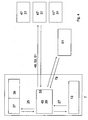
- the symbols of the luminaire depending on the type and test status are displayed according to their stored coordinates. For example, a faulty light with a red symbol, a properly tested with a green or yellow symbol can be displayed. In addition to this color code, steady lights are indicated by a different icon than ready lights, etc. (see FIG. 2 ).
- the energy distributor stores on its internal memory for each lamp the information on which floor plan its luminaire symbol is to be found, as well as the coordinates of its position. If a plan is to be displayed with light symbols, the HTML page is generated via a CGI program, which has the corresponding building plan as background image. For each luminaire to be displayed on the floor plan, an HTML DIV area is created containing the configuration within the enclosure and the position as attributes. The final positioning then takes place via the evaluation of the attributes by a Javascript function, which is the Coordinates are scaled according to the selected magnification level of the map. Icons and map can be scaled separately and collectively in different stages. In addition, the icon is selected according to the configuration and stored test result.
- the positioning of the light symbols can be carried out analogously to the positioning of symbols on the Windows desktop.
- the symbols for the luminaires are selected and positioned in a window of the browser via the input device (mouse, trackball, touchscreen, etc.) present on the second calculation unit.
- the functionality is similar to moving icons on a Windows desktop. So the mouse can be used as an input device.
- the luminaire symbols are selected by clicking with the left mouse button and moved by mouse movements with depressed mouse button to the desired position on the building plan in the browser window.
- a javascript function is triggered that is asynchronous (ie in the background without rebuilding the page in the browser, using the XMLHttpRequest API), identifying the fixture (circuit and luminaire index), and the coordinates on the map to the web server, which updates and saves its configuration files.
- the presented method offers numerous applications, for example, the method can be used to perform the configuration and control of emergency lighting systems. Also, the method can be used to perform the visualization of the test conditions of emergency lighting systems.
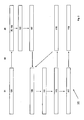
- FIG. 1 discloses a graphical representation of a web-form 57 which, in the context of a recognition effect for the user, is still very strongly oriented on the surface of a customary, hitherto widely used configuration and setting tool.
- Web form 57 can be seen when the web browser is in administrator state 35 could switch.
- the web form 57 can always be seen by a user on a web browser, but a change of plant data 25 can only be permanently stored in the first calculation unit in the administrator state 35.
- the background 41 which offers a tabular frame, is filled by the system data 25.
- the system data 25 describe the emergency lighting system 1 in its current state.
- the representation in FIG. 1 is tabular dominated with few graphics and text elements.
- Continuous light lamps 17 and ready light lamps 19, as well as modified ready light and other lighting categories are connected to one and the same lighting string. From the table of FIG. 1 can also be the position information 23 are taken, which can then be stored in a building plan 43 or displayed on this ( FIG. 2 ). On the basis of the operating mode with permanent light lamps 17 and ready light lamps 19 is to talk of a mixed operation 11.
- FIG. 2 shows the fetched from the graphics memory area of the first calculation unit building plan 43, which is used in the background 41, within the web form 57, to display the system state 27 in the web browser 31 easy to use and controllable.
- the different lighting fixtures such as permanent light fixtures 17, ready light fixtures 19 and other special lights, are operated in mixed mode 11 and also shown.
- the building plan 43 can be available as a GIF file.
- the symbols for the individual lighting fixtures are transmitted to the web browser 31 as CGI parameters.
- a non-functioning lighting fixture can be seen immediately.
- a centrally arranged monitoring room can be set up for one or more buildings, from which all lighting means can be checked and, if necessary, replaced, ie, the condition or status 21 of lighting bodies can be monitored without an electrician permanently monitoring all Building parts must go out regularly.
- FIG. 3 describes in a block diagram 121 a typical communication between a web browser 31 and a web server 29 according to the inventive method via a communication bus 53, which is preferably an Ethernet bus.
- the direction of flow or the direction of communication is indicated by the arrows.
- the administrator page call 101 is initiated by a corresponding password and other switching command chains are transmitted via the communication bus 53 to the web server 29.
- the web server 29 accepts the administrator page call 101 and switches from the previously (not in FIG. 3 If the administrator state 35 is occupied by the web server 29, initially sufficient memory is allocated in the step of the memory allocation 103 in the microcontroller or its external memory. In the configuration copy step 105, the configuration is relocated from permanent memory to main memory. She is available for a change.
- one or more records may be assembled to display a changeable HTML form on the web browser 31.
- the user may customize and modify one or more selected data sets or configuration parameters, such as lighting means position, lighting means state, etc.
- selected events to be accepted such as onmouseclick, onchange, onbutton etc.
- the stored event is called.
- a symbol for a lighting means whether for example continuous light or ready light, can be repositioned or a lighting agent test can be started.
- a CGI transmission 113 is started to send the data of the changed data set as CGI parameters asynchronously to the web server 29 via the communication bus 53.
- the received CGI parameter is parsed out in the parsing step 115 and taken over into the temporarily allocated main memory. If the user, for example an electrician, wishes to change further plant data, new events are triggered after step 111. There is an asynchronous synchronization between web browser 31 and web server 29 permanently event-controlled in the background. Should the user decide that the changes from steps 109, 111, 113, 115 should be permanently preserved, a configuration confirmation 117, e.g. Example, by the operation of a separate button on the web form in the web browser 31, are sent to the web server 29 and the unpopulated data of the temporary memory are stored in the permanent memory, for. As a flash memory, taken over by the production of a resident copy 119.
- a configuration confirmation 117 e.g. Example, by the operation of a separate button on the web form in the web browser 31 are sent to the web server 29 and the unpopulated data of the temporary memory are stored in the permanent memory, for.
- a flash memory taken over by the production of a resident copy 119.
- FIG. 4 schematically shows the hardware connection between the group battery system 7, which may of course also be a central battery system, and one or more calculation units 47, 47 ', 47 "as PCs.
- the calculation units 47, 47', 47" run usual web browser 31. Instead web browser can other programs, such.
- B. Building management systems that access XML data via OPC, run on a computing unit 47.
- the calculation units 47, 47 ', 47 " which can be connected to the group battery system 7 via a remote connection 49, can connect to the first calculation unit 45 via the interface 55.
- the interface 55 is part of the calculation unit 45.
- the calculation unit 45 which may be a microcontroller with peripherals such as the illustrated external memories 37, 39, runs a web server 29.
- the microcontroller is designed so that it can monitor final circuits 13 and other electronic assemblies and record, edit and change the system state 27.
- the system data 25 resulting from the system state 27 are written into the memories 37, 39 and read out of the memories 37, 39.
- the remote connection 49 is a communication bus 53, via which data sets 51, eg in the form of CGI data parameters,
- the memories 37, 39, of which one memory 39 is a graphics chip eicher, can - as shown graphically - be different sizes. They can also be dynamically allocated according to the requirements arising from the data volumes, in particular to and from the web browser 31.
- the memories can also be part of the microcontroller as internal memory.
- the group battery system 7 thus includes electronics, such as microcontroller, calculation units 45, at least one web server 29, memory 37, 39 and final circuits 13 as electrical components. Another part is the battery system 61, which via a controller 79 with the help of a charging electronics switched on and wegschaltbar or in a state of charge can be set.
- a controller 79 As a very useful communication bus 53, an Ethernet connection based on a TCP / IP layer has proven to transmit an HTTP protocol with embedded Javascript or AJAX. Small CGI parameter packets form records 51.
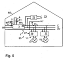
- FIG. 5 shows an electrical plan of a building installation 67 in a schematic representation in which the inventive communication method for controlling, monitoring, maintenance, control and monitoring of lighting means in the mixed operation 11 can be used.
- Part of the building installation 67 are the first, 45, and second (in FIG. 5 not shown) calculation units.
- the building installation 67 of a building 65 usually hangs electrically on a central supply network 59, z. B. an energy supplier. Despite high security of supply states must be intercepted because the supply voltage of the supply network 59, at least in one Lighting strand 15, can collapse.
- voltage monitors 63 are provided at suitable locations within the building installation. When the voltage falls below a limit value, additional energy can be fed from a central battery system 5 into a power distributor 3.
- the power distributor 3 may be both a main distributor 69 and a sub-distributor 71.
- at least one DC voltage source 9 is kept somewhere in or on the building 65, which can also be a battery installation 61.
- the energy distributor 3 is equipped with at least one calculation unit 45, for example a microcontroller circuit.
- End circuit side to the main manifold 69 and possibly to the sub-manifold 71 are consumers, so-called final circuits 13, connected.
- Some of the final circuits 13 may be permanent light lamps 17 with and without corresponding ballasts 75 and ready light lamps 19 with state followers 77.
- the status followers 77 can be constructed with and without integrated ballasts.
- Part of the lighting string 15 is the portion of the illumination means, ie the lighting medium strand 73.
- Safety lighting system 1 is usually in the general user state 33, from which it can switch by means of special inputs, passwords or other state changes to an administrator state.
- the phase conductor L ', L "and the neutral conductor N', N" are preferably routed via the energy distributor, while the protective conductor PE ', PE "is often not routed via the energy distributor 3.
- control Fig. 4 101 Administrator page view Fig. 3 103 Memory allocation Fig. 3 105 configuration copy Fig. 3 107 HTML form generation Fig. 3 109 configuration adjustment Fig. 3 111 event call Fig. 3 113 CGI transfer Fig. 3 115 parsing Fig. 3 117 configuration confirmation Fig. 3 119 Resident copy Fig. 3 121 block diagram Fig. 3 L ', L " Phase or positive conductor Fig. 5 N ', N " Neutral conductor or negative conductor Fig. 5 PE ', PE " Protective conductor or earth conductor Fig. 5
Landscapes
- Engineering & Computer Science (AREA)
- Computer Networks & Wireless Communication (AREA)
- Signal Processing (AREA)
- Circuit Arrangement For Electric Light Sources In General (AREA)
Claims (12)
- Distributeur d'énergie (3) commandé par microcontrôleur pour des installations d'éclairage de sécurité (1), ledit distributeur pouvant activer en mode mixte (11) au moins un luminaire pour éclairage de secours de type permanent (17) et au moins un luminaire pour éclairage de secours de type non-permanent (19) ;
caractérisé en ce que :le distributeur d'énergie (3) est équipé d'au moins une interface (55) pour un protocole de transfert hypertexte HTP ;et qu'un serveur Web (29) offrant l'interface (55) au protocole de transfert hypertexte HTP est installé dans le microcontrôleur (45) du distributeur d'énergie, avec lequel les données relatives aux installations (25) de l'installation d'éclairage de sécurité (1) peuvent être gérées ;et qui fonctionne selon un mécanisme JavaScript et XML asynchrone. - Distributeur d'énergie (3) selon la revendication 1, caractérisé en ce que le serveur Web (29) présente le plan de connexion des données relatives aux installations (25).
- Distributeur d'énergie (3) selon l'une quelconque des revendications précédentes, caractérisé en ce que les données relatives aux installations (25) comprennent des informations de position (23) sur les différents moyens d'éclairage (15, 17, 19) tels que les luminaires pour éclairage de secours de type non-permanent (19) et les luminaires pour éclairage de secours de type permanent (17) ;
des informations d'état (21) étant de préférence mémorisées en plus des informations de position (23), de sorte que le distributeur d'énergie (3) puisse garantir qu'au moins quelques-uns des moyens d'éclairage (17, 19) pourront continuer à fonctionner en cas de recours à une source de courant continu (7, 9, 61), en cas de panne de courant secteur. - Distributeur d'énergie (3) selon l'une quelconque des revendications précédentes, caractérisé en ce que :l'interface (55) permet de transmettre (53) les données relatives aux installations (25) dans un mode asynchrone sous une forme permettant la navigation (113, 115) à la suite de demandes externes de navigation ;la mise à disposition des données relatives aux installations (25) pouvant de préférence être initiées de telle sorte par un programme de traitement des événements Javascript que la transmission asynchrone des données relatives aux installations (25) est effectuée pendant la modification des données relatives aux installations (25).
- Distributeur d'énergie (3) selon l'une quelconque des revendications précédentes, caractérisé en ce que :le serveur Web (29) peut être réglé dans un état d'utilisation générale (33) et dans un état d'utilisation par l'administrateur (35),les données relatives aux installations (25) ne pouvant de préférence être modifiées que dans l'état d'utilisation par l'administrateur (35) via un protocole de transfert hypertexte HTP, alors que les données relatives aux installations (25) ne sont en grande mesure accessibles qu'en lecture simple dans l'état d'utilisation générale (33).
- Distributeur d'énergie (3) selon la revendication 5, caractérisé en ce que lorsque l'on passe dans l'état d'utilisation par l'administrateur (35), une zone de mémoire (37, 39) destinée au microcontrôleur (45) est allouée (103) de façon dynamique aux données relatives aux installations (25) de façon à ce que les données relatives aux installations (25) se trouvent dans au moins un formulaire HTML sous la forme d'un jeu de données relatives aux installations, notamment après transmission à un navigateur (31) ;
le jeu de données relatives aux installations pouvant de préférence être adapté de façon dynamique en fonction des événements transmis via le protocole de transfert hypertexte HTP, notamment sous la forme de jeux de paramètres CGI (113) et la zone de mémoire (37, 39) allouée pouvant ainsi être adaptée à la place nécessaire en mémoire pour une structure de données temporaire permettant de modifier au moins un jeu de données relatives aux installations. - Distributeur d'énergie (3) selon l'une quelconque des revendications précédentes, caractérisé en ce que les données relatives aux installations (25) sont transmises par au moins un distributeur d'énergie (3) par l'intermédiaire de l'interface (55) sous la forme de données XML codées transmises à une unité de gestion de bâtiment subordonnée, par exemple à une unité de calcul (47, 47', 47"), notamment à la demande de l'unité de calcul (47, 47', 47").
- Distributeur d'énergie (3) selon l'une quelconque des revendications précédentes, caractérisé en ce que dans un système de fichier Flash, tant les données d'au moins un fichier de configuration que les plans de bâtiment graphiques (43) peuvent être classés de façon permanente.
- Distributeur d'énergie (3) selon l'une quelconque des revendications précédentes, caractérisé en ce que, parallèlement aux données relatives aux installations destinées au microcontrôleur (45), une zone de mémoire graphique (39) est réservée dans laquelle des plans de bâtiment (43) graphiques peuvent être classés, notamment via un protocole de transfert de fichiers FTP.
- Procédé de gestion et de pilotage d'une installation d'éclairage de sécurité (1) pour le fonctionnement en mode mixte (11) d'une chaîne de moyens d'éclairage (15) reliée au courant qui relie entre elles de façon communicante au moins deux unités de calcul (45, 47, 47', 47"),
caractérisé en ce que :une des unités de calcul (45) est un microcontrôleur équipé d'un serveur Web (29) qui reste relié à la deuxième unité de calcul (47, 47' 47") informatique typique par l'intermédiaire d'un protocole de transfert hypertexte HTP, pour échanger notamment les données relatives aux installations (25) de l'installation d'éclairage de sécurité (1) entre la première et la seconde unité de calcul (45, 47, 47', 47") par l'intermédiaire d'un protocole JavaScript et XML asynchrone. - Procédé de gestion et de pilotage selon la revendication 10, caractérisé en ce que :un navigateur (31) tourne sur la deuxième unité de calcul (47, 47', 47"), reliée notamment à la première unité de calcul (45) par l'intermédiaire d'une connexion à distance (53), ledit navigateur reproduisant des jeux de données adaptés de façon dynamique composés de données relatives aux installations (25) sur un arrière-plan (41) provenant de la première unité de calcul (45), qui représente au moins en partie un bâtiment (65) de l'installation d'éclairage de sécurité (1);les différents jeux de données représentant notamment de façon graphique l'état (21) des corps d'éclairage (17, 19) d'une chaine d'éclairages (15).
- Procédé de gestion et de pilotage selon l'une quelconque des revendications 10 à 11, caractérisé en ce que :seules sont transmises par l'intermédiaire du protocole de transfert hypertexte HTP les données devant être modifiées, lesdites données étant classées automatiquement dans la première unité de calcul (45) suivant un processus de modification pour une mémorisation sur le serveur Web (29) dans une zone de mémoire (37, 39) prévue pour les données relatives aux installations (25).
Priority Applications (3)
| Application Number | Priority Date | Filing Date | Title |
|---|---|---|---|
| AT08075041T ATE466474T1 (de) | 2008-01-09 | 2008-01-09 | Mikrokontroller-gesteuerte notlichtbeleuchtungsanlage und geeignetes kommunikationsverfahren hierfür |
| DE502008000597T DE502008000597D1 (de) | 2008-01-09 | 2008-01-09 | Mikrokontroller-gesteuerte Notlichtbeleuchtungsanlage und geeignetes Kommunikationsverfahren hierfür |
| EP08075041A EP2081415B1 (fr) | 2008-01-09 | 2008-01-09 | Installation d'éclairage d'urgence commandée par microcontrôleur et procédé de communication approprié |
Applications Claiming Priority (1)
| Application Number | Priority Date | Filing Date | Title |
|---|---|---|---|
| EP08075041A EP2081415B1 (fr) | 2008-01-09 | 2008-01-09 | Installation d'éclairage d'urgence commandée par microcontrôleur et procédé de communication approprié |
Publications (2)
| Publication Number | Publication Date |
|---|---|
| EP2081415A1 EP2081415A1 (fr) | 2009-07-22 |
| EP2081415B1 true EP2081415B1 (fr) | 2010-04-28 |
Family
ID=39708411
Family Applications (1)
| Application Number | Title | Priority Date | Filing Date |
|---|---|---|---|
| EP08075041A Active EP2081415B1 (fr) | 2008-01-09 | 2008-01-09 | Installation d'éclairage d'urgence commandée par microcontrôleur et procédé de communication approprié |
Country Status (3)
| Country | Link |
|---|---|
| EP (1) | EP2081415B1 (fr) |
| AT (1) | ATE466474T1 (fr) |
| DE (1) | DE502008000597D1 (fr) |
Cited By (8)
| Publication number | Priority date | Publication date | Assignee | Title |
|---|---|---|---|---|
| DE102010016392A1 (de) | 2010-04-11 | 2011-10-13 | Rp-Technik E.K. | Anbindung einer Melde- und Testeinrichtung einer Sicherheitsbeleuchtungsanlage an ein Gebäudeleitsystem |
| EP2573630A1 (fr) | 2011-09-23 | 2013-03-27 | RP-Technik e. K. | Installation d'éclairage de secours équipée de fonctions de communication de données |
| DE202013100811U1 (de) | 2013-02-25 | 2014-06-02 | Rp-Technik E.K. | Energieversorgungseinrichtung mit Batterieüberwachung |
| EP2770605A1 (fr) | 2013-02-25 | 2014-08-27 | RP-Technik e. K. | Dispositif d'alimentation en énergie avec surveillance de la batterie et procédé de surveillance de la batterie |
| EP2911269A1 (fr) | 2014-02-24 | 2015-08-26 | RP-Technik GmbH | Dispositif d'alimentation en énergie avec surveillance de la batterie et procédé de surveillance de la batterie |
| EP3391713B1 (fr) | 2016-06-13 | 2020-08-12 | Zumtobel Lighting GmbH | Protocolisation décentralisé des états de fonctionnement de composants de la technique du bâtiment |
| DE102021105552A1 (de) | 2020-03-08 | 2021-09-09 | Rp-Technik Gmbh | Notlichtbeleuchtungsanlage, erstellt aus autark operierenden Modulen, und Betrieb einer Notlichtbeleuchtungsanlage mit autark operierenden Modulen |
| DE102021105701B4 (de) | 2020-03-09 | 2023-06-15 | Rp-Technik Gmbh | Notlichtbeleuchtungsanlage mit zentral abgelegten und verwalteten Anlagendaten |
Families Citing this family (2)
| Publication number | Priority date | Publication date | Assignee | Title |
|---|---|---|---|---|
| DE102008017533C5 (de) * | 2008-04-03 | 2011-06-16 | Rp-Technik E.K. | Sicherheitsbeleuchtungsanlage mit einem Splitter |
| DE102010039406A1 (de) * | 2010-08-17 | 2012-02-23 | Zumtobel Lighting Gmbh | Busphasenwächter |
Family Cites Families (5)
| Publication number | Priority date | Publication date | Assignee | Title |
|---|---|---|---|---|
| WO2001093399A2 (fr) * | 2000-06-02 | 2001-12-06 | Astec International Limited | Interface utilisateur eloignee, activee par navigateur et analyseur d'expansion automatise destine a des systemes d'alimentation d'equipements de telecommunications |
| US20030103075A1 (en) * | 2001-12-03 | 2003-06-05 | Rosselot Robert Charles | System and method for control of conference facilities and equipment |
| EP1513376B1 (fr) | 2003-09-04 | 2017-04-12 | Eaton Safety IP GmbH & Co. KG | Système d'éclairage |
| US20050206241A1 (en) * | 2004-03-17 | 2005-09-22 | Piyush Saxena | Web-enabled UPS |
| CN100437579C (zh) | 2005-12-20 | 2008-11-26 | 腾讯科技(深圳)有限公司 | 一种实现ajax网页的方法 |
-
2008
- 2008-01-09 EP EP08075041A patent/EP2081415B1/fr active Active
- 2008-01-09 DE DE502008000597T patent/DE502008000597D1/de active Active
- 2008-01-09 AT AT08075041T patent/ATE466474T1/de active
Cited By (21)
| Publication number | Priority date | Publication date | Assignee | Title |
|---|---|---|---|---|
| DE102010016392B4 (de) * | 2010-04-11 | 2016-02-18 | Rp-Technik Gmbh | Schnittstelle zur Anbindung einer Melde- und Testeinrichtung einer Sicherheitsbeleuchtungsanlage an ein Gebäudeleitsystem, insbesondere in einem Bauwerk, und dazugehöriges Verfahren |
| DE102010016392A1 (de) | 2010-04-11 | 2011-10-13 | Rp-Technik E.K. | Anbindung einer Melde- und Testeinrichtung einer Sicherheitsbeleuchtungsanlage an ein Gebäudeleitsystem |
| DE102011053883B4 (de) | 2011-09-23 | 2022-03-10 | Rp-Technik Gmbh | Notlichtbeleuchtungsanlage mit Datenkommunikationsfähigkeiten |
| EP2573630A1 (fr) | 2011-09-23 | 2013-03-27 | RP-Technik e. K. | Installation d'éclairage de secours équipée de fonctions de communication de données |
| DE102011053883A1 (de) * | 2011-09-23 | 2013-03-28 | Rp-Technik E.K. | Notlichtbeleuchtungsanlage mit Datenkommunikationsfähigkeiten |
| DE202013100811U1 (de) | 2013-02-25 | 2014-06-02 | Rp-Technik E.K. | Energieversorgungseinrichtung mit Batterieüberwachung |
| EP2770605A1 (fr) | 2013-02-25 | 2014-08-27 | RP-Technik e. K. | Dispositif d'alimentation en énergie avec surveillance de la batterie et procédé de surveillance de la batterie |
| DE102014102366A1 (de) | 2013-02-25 | 2014-10-02 | Rp-Technik E.K. | Energieversorgungseinrichtung mit Batterieüberwachung und Batterieüberwachungsverfahren |
| DE102014102366B4 (de) * | 2013-02-25 | 2021-03-04 | Rp-Technik Gmbh | Energieversorgungseinrichtung mit Batterieüberwachung und Batterieüberwachungsverfahren |
| EP2911269A1 (fr) | 2014-02-24 | 2015-08-26 | RP-Technik GmbH | Dispositif d'alimentation en énergie avec surveillance de la batterie et procédé de surveillance de la batterie |
| EP3391713B1 (fr) | 2016-06-13 | 2020-08-12 | Zumtobel Lighting GmbH | Protocolisation décentralisé des états de fonctionnement de composants de la technique du bâtiment |
| DE102021105552A1 (de) | 2020-03-08 | 2021-09-09 | Rp-Technik Gmbh | Notlichtbeleuchtungsanlage, erstellt aus autark operierenden Modulen, und Betrieb einer Notlichtbeleuchtungsanlage mit autark operierenden Modulen |
| DE102021105553A1 (de) | 2020-03-08 | 2021-09-09 | Rp-Technik Gmbh | Notlichtbeleuchtungsanlage mit Fail-Safe-Funktion und Verfahren zu ihrem Betrieb |
| EP3879940A1 (fr) | 2020-03-08 | 2021-09-15 | RP-Technik GmbH | Système d'éclairage d'urgence, créé à partir de modules à fonctionnement autonome, et fonctionnement d'une installation d'éclairage d'urgence pourvue de modules à fonctionnement autonome |
| EP3879941A1 (fr) | 2020-03-08 | 2021-09-15 | RP-Technik GmbH | Installation d'éclairage d'urgence à fonction d'arrêt en sécurité et son procédé de fonctionnement |
| EP3879942A1 (fr) | 2020-03-08 | 2021-09-15 | RP-Technik GmbH | Système d'éclairage d'urgence doté d'un bus interne continu vers l'extérieur et son procédé de fonctionnement, ainsi que procédé de fabrication |
| DE102021105554A1 (de) | 2020-03-08 | 2021-09-09 | Rp-Technik Gmbh | Modular aufgebaute Notlichtbeleuchtungsanlage mit einem seriellen Bus und Verarbeitung von Signalen auf dem Bus sowie Herstellung einer entsprechenden Notlichtbeleuchtungsanlage |
| DE102021105552B4 (de) | 2020-03-08 | 2022-12-01 | Rp-Technik Gmbh | Notlichtbeleuchtungsanlage, erstellt aus autark operierenden Modulen, und Betrieb einer Notlichtbeleuchtungsanlage mit autark operierenden Modulen |
| DE102021105553B4 (de) | 2020-03-08 | 2023-03-02 | Rp-Technik Gmbh | Notlichtbeleuchtungsanlage mit Fail-Safe-Funktion und Verfahren zu ihrem Betrieb |
| DE102021105554B4 (de) | 2020-03-08 | 2024-06-20 | Rp-Technik Gmbh | Modular aufgebaute Notlichtbeleuchtungsanlage mit einem seriellen Bus und Verarbeitung von Signalen auf dem Bus sowie Herstellung einer entsprechenden Notlichtbeleuchtungsanlage |
| DE102021105701B4 (de) | 2020-03-09 | 2023-06-15 | Rp-Technik Gmbh | Notlichtbeleuchtungsanlage mit zentral abgelegten und verwalteten Anlagendaten |
Also Published As
| Publication number | Publication date |
|---|---|
| DE502008000597D1 (de) | 2010-06-10 |
| ATE466474T1 (de) | 2010-05-15 |
| EP2081415A1 (fr) | 2009-07-22 |
Similar Documents
| Publication | Publication Date | Title |
|---|---|---|
| EP2081415B1 (fr) | Installation d'éclairage d'urgence commandée par microcontrôleur et procédé de communication approprié | |
| DE102008017292A1 (de) | Computergestütztes System zur Verwaltung und/oder Steuerung eines Gebäudemanagementsystems | |
| DE19546831A1 (de) | Verfahren zum Managen von Installationen in Gebäuden | |
| WO2005022286A2 (fr) | Procede de projection graphique de la commande d'une installation technique a projection integree d'appareils d'exploitation, y compris un systeme de projection et un progiciel informatique | |
| EP0825740B1 (fr) | Circuit et méthode pour controler des appareils électriques domestiques | |
| WO2013064189A1 (fr) | Migration d'une machine virtuelle | |
| EP2883294B1 (fr) | Procédé de commande assistée par ordinateur d'un réseau de distribution d'énergie électrique composé d'une pluralité de noeuds | |
| DE102004030781A1 (de) | SCADA-System und Verfahren zum Betreiben eines solchen Systems | |
| DE19817073A1 (de) | Vorrichtung zur Steuerung einer Mehrzahl von Beleuchtungselementen | |
| DE102016120081A1 (de) | Verfahren zur Inbetriebnahme und/oder Wartung einer Brandmelder- und/oder Löschsteuerzentrale sowie Vorrichtung dafür | |
| DE10053665A1 (de) | Prozeß-Leitsystem zur Fern-Überwachung und -Steuerung von verfahrenstechnischen Prozessen über das Internet | |
| DE102010016392B4 (de) | Schnittstelle zur Anbindung einer Melde- und Testeinrichtung einer Sicherheitsbeleuchtungsanlage an ein Gebäudeleitsystem, insbesondere in einem Bauwerk, und dazugehöriges Verfahren | |
| DE19800448C2 (de) | Überwachungsanlage | |
| DE102011101387A1 (de) | Tragbares Anzeige- und Bediengerät | |
| DE19747054C1 (de) | Datenübertragungssystem für die Ausbausteuerung eines Gewinnungsbetriebs im Untertagebergbau | |
| DE102010016165A1 (de) | Verfahren zum Betreiben eines Gebäudeinstallationssystems sowie Gebäudeinstallationssystem | |
| DE19847901C1 (de) | Datenübertragungssystem für die Ausbausteuerung eines Gewinnungsbetriebs im Untertagebergbau | |
| EP3664380B1 (fr) | Concept d'étages pouvant être mis à niveau pour systèmes d'éclairage | |
| EP3988384B1 (fr) | Procédé mis en uvre par ordinateur et dispositif de gestion de charge locale des stations de charge permettant de charger des véhicules électriques dans un système de station de charge | |
| DE112006000806T5 (de) | Verfahren und Vorrichtung zum Verwalten eines Objekts sowie Teilen davon | |
| EP3847516B1 (fr) | Identification des contrôleurs dans un système d'automatisation | |
| DE19927821B4 (de) | Transportables, modulares Informationssystem für bussystemgestützte Anwendungen | |
| DE102012204686B3 (de) | Verfahren zur Konfiguration einer Beleuchtungsanlage | |
| DE102024000556A1 (de) | Verfahren zum Betrieb eines Steuergerätes zur Steuerung von Netzwerkswitchen | |
| EP4212975A1 (fr) | Procédé de configuration d'un réseau de commande, ainsi que réseau de commande, programme informatique et support lisible par ordinateur |
Legal Events
| Date | Code | Title | Description |
|---|---|---|---|
| PUAI | Public reference made under article 153(3) epc to a published international application that has entered the european phase |
Free format text: ORIGINAL CODE: 0009012 |
|
| GRAP | Despatch of communication of intention to grant a patent |
Free format text: ORIGINAL CODE: EPIDOSNIGR1 |
|
| 17P | Request for examination filed |
Effective date: 20090321 |
|
| AK | Designated contracting states |
Kind code of ref document: A1 Designated state(s): AT BE BG CH CY CZ DE DK EE ES FI FR GB GR HR HU IE IS IT LI LT LU LV MC MT NL NO PL PT RO SE SI SK TR |
|
| AX | Request for extension of the european patent |
Extension state: AL BA MK RS |
|
| GRAS | Grant fee paid |
Free format text: ORIGINAL CODE: EPIDOSNIGR3 |
|
| GRAA | (expected) grant |
Free format text: ORIGINAL CODE: 0009210 |
|
| AKX | Designation fees paid |
Designated state(s): AT BE BG CH CY CZ DE DK EE ES FI FR GB GR HR HU IE IS IT LI LT LU LV MC MT NL NO PL PT RO SE SI SK TR |
|
| AK | Designated contracting states |
Kind code of ref document: B1 Designated state(s): AT BE BG CH CY CZ DE DK EE ES FI FR GB GR HR HU IE IS IT LI LT LU LV MC MT NL NO PL PT RO SE SI SK TR |
|
| REG | Reference to a national code |
Ref country code: GB Ref legal event code: FG4D Free format text: NOT ENGLISH |
|
| REG | Reference to a national code |
Ref country code: CH Ref legal event code: EP |
|
| REG | Reference to a national code |
Ref country code: IE Ref legal event code: FG4D Free format text: LANGUAGE OF EP DOCUMENT: GERMAN |
|
| REF | Corresponds to: |
Ref document number: 502008000597 Country of ref document: DE Date of ref document: 20100610 Kind code of ref document: P |
|
| REG | Reference to a national code |
Ref country code: NL Ref legal event code: VDEP Effective date: 20100428 |
|
| LTIE | Lt: invalidation of european patent or patent extension |
Effective date: 20100428 |
|
| PG25 | Lapsed in a contracting state [announced via postgrant information from national office to epo] |
Ref country code: SE Free format text: LAPSE BECAUSE OF FAILURE TO SUBMIT A TRANSLATION OF THE DESCRIPTION OR TO PAY THE FEE WITHIN THE PRESCRIBED TIME-LIMIT Effective date: 20100428 Ref country code: ES Free format text: LAPSE BECAUSE OF FAILURE TO SUBMIT A TRANSLATION OF THE DESCRIPTION OR TO PAY THE FEE WITHIN THE PRESCRIBED TIME-LIMIT Effective date: 20100808 Ref country code: LT Free format text: LAPSE BECAUSE OF FAILURE TO SUBMIT A TRANSLATION OF THE DESCRIPTION OR TO PAY THE FEE WITHIN THE PRESCRIBED TIME-LIMIT Effective date: 20100428 Ref country code: NL Free format text: LAPSE BECAUSE OF FAILURE TO SUBMIT A TRANSLATION OF THE DESCRIPTION OR TO PAY THE FEE WITHIN THE PRESCRIBED TIME-LIMIT Effective date: 20100428 Ref country code: NO Free format text: LAPSE BECAUSE OF FAILURE TO SUBMIT A TRANSLATION OF THE DESCRIPTION OR TO PAY THE FEE WITHIN THE PRESCRIBED TIME-LIMIT Effective date: 20100728 |
|
| REG | Reference to a national code |
Ref country code: IE Ref legal event code: FD4D |
|
| PG25 | Lapsed in a contracting state [announced via postgrant information from national office to epo] |
Ref country code: SI Free format text: LAPSE BECAUSE OF FAILURE TO SUBMIT A TRANSLATION OF THE DESCRIPTION OR TO PAY THE FEE WITHIN THE PRESCRIBED TIME-LIMIT Effective date: 20100428 Ref country code: HR Free format text: LAPSE BECAUSE OF FAILURE TO SUBMIT A TRANSLATION OF THE DESCRIPTION OR TO PAY THE FEE WITHIN THE PRESCRIBED TIME-LIMIT Effective date: 20100428 Ref country code: FI Free format text: LAPSE BECAUSE OF FAILURE TO SUBMIT A TRANSLATION OF THE DESCRIPTION OR TO PAY THE FEE WITHIN THE PRESCRIBED TIME-LIMIT Effective date: 20100428 Ref country code: LV Free format text: LAPSE BECAUSE OF FAILURE TO SUBMIT A TRANSLATION OF THE DESCRIPTION OR TO PAY THE FEE WITHIN THE PRESCRIBED TIME-LIMIT Effective date: 20100428 Ref country code: IS Free format text: LAPSE BECAUSE OF FAILURE TO SUBMIT A TRANSLATION OF THE DESCRIPTION OR TO PAY THE FEE WITHIN THE PRESCRIBED TIME-LIMIT Effective date: 20100828 |
|
| PG25 | Lapsed in a contracting state [announced via postgrant information from national office to epo] |
Ref country code: CY Free format text: LAPSE BECAUSE OF FAILURE TO SUBMIT A TRANSLATION OF THE DESCRIPTION OR TO PAY THE FEE WITHIN THE PRESCRIBED TIME-LIMIT Effective date: 20100616 Ref country code: PL Free format text: LAPSE BECAUSE OF FAILURE TO SUBMIT A TRANSLATION OF THE DESCRIPTION OR TO PAY THE FEE WITHIN THE PRESCRIBED TIME-LIMIT Effective date: 20100428 |
|
| PG25 | Lapsed in a contracting state [announced via postgrant information from national office to epo] |
Ref country code: EE Free format text: LAPSE BECAUSE OF FAILURE TO SUBMIT A TRANSLATION OF THE DESCRIPTION OR TO PAY THE FEE WITHIN THE PRESCRIBED TIME-LIMIT Effective date: 20100428 Ref country code: DK Free format text: LAPSE BECAUSE OF FAILURE TO SUBMIT A TRANSLATION OF THE DESCRIPTION OR TO PAY THE FEE WITHIN THE PRESCRIBED TIME-LIMIT Effective date: 20100428 Ref country code: IE Free format text: LAPSE BECAUSE OF FAILURE TO SUBMIT A TRANSLATION OF THE DESCRIPTION OR TO PAY THE FEE WITHIN THE PRESCRIBED TIME-LIMIT Effective date: 20100428 |
|
| PG25 | Lapsed in a contracting state [announced via postgrant information from national office to epo] |
Ref country code: RO Free format text: LAPSE BECAUSE OF FAILURE TO SUBMIT A TRANSLATION OF THE DESCRIPTION OR TO PAY THE FEE WITHIN THE PRESCRIBED TIME-LIMIT Effective date: 20100428 Ref country code: CZ Free format text: LAPSE BECAUSE OF FAILURE TO SUBMIT A TRANSLATION OF THE DESCRIPTION OR TO PAY THE FEE WITHIN THE PRESCRIBED TIME-LIMIT Effective date: 20100428 Ref country code: SK Free format text: LAPSE BECAUSE OF FAILURE TO SUBMIT A TRANSLATION OF THE DESCRIPTION OR TO PAY THE FEE WITHIN THE PRESCRIBED TIME-LIMIT Effective date: 20100428 |
|
| PLBE | No opposition filed within time limit |
Free format text: ORIGINAL CODE: 0009261 |
|
| STAA | Information on the status of an ep patent application or granted ep patent |
Free format text: STATUS: NO OPPOSITION FILED WITHIN TIME LIMIT |
|
| PG25 | Lapsed in a contracting state [announced via postgrant information from national office to epo] |
Ref country code: IT Free format text: LAPSE BECAUSE OF FAILURE TO SUBMIT A TRANSLATION OF THE DESCRIPTION OR TO PAY THE FEE WITHIN THE PRESCRIBED TIME-LIMIT Effective date: 20100428 |
|
| 26N | No opposition filed |
Effective date: 20110131 |
|
| PG25 | Lapsed in a contracting state [announced via postgrant information from national office to epo] |
Ref country code: GR Free format text: LAPSE BECAUSE OF FAILURE TO SUBMIT A TRANSLATION OF THE DESCRIPTION OR TO PAY THE FEE WITHIN THE PRESCRIBED TIME-LIMIT Effective date: 20100729 |
|
| BERE | Be: lapsed |
Owner name: RP-TECHNIK E. K. Effective date: 20110131 |
|
| PG25 | Lapsed in a contracting state [announced via postgrant information from national office to epo] |
Ref country code: MC Free format text: LAPSE BECAUSE OF NON-PAYMENT OF DUE FEES Effective date: 20110131 |
|
| REG | Reference to a national code |
Ref country code: FR Ref legal event code: ST Effective date: 20110930 |
|
| PG25 | Lapsed in a contracting state [announced via postgrant information from national office to epo] |
Ref country code: FR Free format text: LAPSE BECAUSE OF NON-PAYMENT OF DUE FEES Effective date: 20110131 |
|
| PG25 | Lapsed in a contracting state [announced via postgrant information from national office to epo] |
Ref country code: BE Free format text: LAPSE BECAUSE OF NON-PAYMENT OF DUE FEES Effective date: 20110131 |
|
| PG25 | Lapsed in a contracting state [announced via postgrant information from national office to epo] |
Ref country code: MT Free format text: LAPSE BECAUSE OF FAILURE TO SUBMIT A TRANSLATION OF THE DESCRIPTION OR TO PAY THE FEE WITHIN THE PRESCRIBED TIME-LIMIT Effective date: 20100428 |
|
| REG | Reference to a national code |
Ref country code: CH Ref legal event code: PL |
|
| GBPC | Gb: european patent ceased through non-payment of renewal fee |
Effective date: 20120109 |
|
| PG25 | Lapsed in a contracting state [announced via postgrant information from national office to epo] |
Ref country code: CH Free format text: LAPSE BECAUSE OF NON-PAYMENT OF DUE FEES Effective date: 20120131 Ref country code: GB Free format text: LAPSE BECAUSE OF NON-PAYMENT OF DUE FEES Effective date: 20120109 Ref country code: LI Free format text: LAPSE BECAUSE OF NON-PAYMENT OF DUE FEES Effective date: 20120131 |
|
| PG25 | Lapsed in a contracting state [announced via postgrant information from national office to epo] |
Ref country code: LU Free format text: LAPSE BECAUSE OF NON-PAYMENT OF DUE FEES Effective date: 20110109 |
|
| PG25 | Lapsed in a contracting state [announced via postgrant information from national office to epo] |
Ref country code: PT Free format text: LAPSE BECAUSE OF NON-PAYMENT OF DUE FEES Effective date: 20100428 |
|
| PG25 | Lapsed in a contracting state [announced via postgrant information from national office to epo] |
Ref country code: TR Free format text: LAPSE BECAUSE OF FAILURE TO SUBMIT A TRANSLATION OF THE DESCRIPTION OR TO PAY THE FEE WITHIN THE PRESCRIBED TIME-LIMIT Effective date: 20100428 Ref country code: BG Free format text: LAPSE BECAUSE OF FAILURE TO SUBMIT A TRANSLATION OF THE DESCRIPTION OR TO PAY THE FEE WITHIN THE PRESCRIBED TIME-LIMIT Effective date: 20100728 |
|
| PG25 | Lapsed in a contracting state [announced via postgrant information from national office to epo] |
Ref country code: HU Free format text: LAPSE BECAUSE OF FAILURE TO SUBMIT A TRANSLATION OF THE DESCRIPTION OR TO PAY THE FEE WITHIN THE PRESCRIBED TIME-LIMIT Effective date: 20100428 |
|
| REG | Reference to a national code |
Ref country code: DE Ref legal event code: R082 Ref document number: 502008000597 Country of ref document: DE Representative=s name: CREMER & CREMER, DE |
|
| REG | Reference to a national code |
Ref country code: DE Ref legal event code: R082 Ref document number: 502008000597 Country of ref document: DE Representative=s name: CREMER & CREMER, DE Effective date: 20150413 Ref country code: DE Ref legal event code: R081 Ref document number: 502008000597 Country of ref document: DE Owner name: RP-TECHNIK GMBH, DE Free format text: FORMER OWNER: RP-TECHNIK E.K., 63110 RODGAU, DE Effective date: 20150413 |
|
| REG | Reference to a national code |
Ref country code: AT Ref legal event code: PC Ref document number: 466474 Country of ref document: AT Kind code of ref document: T Owner name: RP-TECHNIK GMBH, DE Effective date: 20150904 |
|
| PGFP | Annual fee paid to national office [announced via postgrant information from national office to epo] |
Ref country code: AT Payment date: 20220113 Year of fee payment: 15 |
|
| REG | Reference to a national code |
Ref country code: AT Ref legal event code: MM01 Ref document number: 466474 Country of ref document: AT Kind code of ref document: T Effective date: 20230109 |
|
| PG25 | Lapsed in a contracting state [announced via postgrant information from national office to epo] |
Ref country code: AT Free format text: LAPSE BECAUSE OF NON-PAYMENT OF DUE FEES Effective date: 20230109 |
|
| PGFP | Annual fee paid to national office [announced via postgrant information from national office to epo] |
Ref country code: DE Payment date: 20260227 Year of fee payment: 19 |