EP2081824B1 - Circuit de refroidissement multi-étages pour composants électroniques d'un aéronef - Google Patents
Circuit de refroidissement multi-étages pour composants électroniques d'un aéronef Download PDFInfo
- Publication number
- EP2081824B1 EP2081824B1 EP07846695A EP07846695A EP2081824B1 EP 2081824 B1 EP2081824 B1 EP 2081824B1 EP 07846695 A EP07846695 A EP 07846695A EP 07846695 A EP07846695 A EP 07846695A EP 2081824 B1 EP2081824 B1 EP 2081824B1
- Authority
- EP
- European Patent Office
- Prior art keywords
- coolant
- aircraft
- heat exchanger
- electronic system
- electronic
- Prior art date
- Legal status (The legal status is an assumption and is not a legal conclusion. Google has not performed a legal analysis and makes no representation as to the accuracy of the status listed.)
- Not-in-force
Links
- 238000001816 cooling Methods 0.000 title claims abstract description 101
- 239000002826 coolant Substances 0.000 claims abstract description 212
- 239000007788 liquid Substances 0.000 claims description 61
- XLYOFNOQVPJJNP-UHFFFAOYSA-N water Substances O XLYOFNOQVPJJNP-UHFFFAOYSA-N 0.000 claims description 22
- 239000013505 freshwater Substances 0.000 claims description 17
- 238000001179 sorption measurement Methods 0.000 claims description 12
- 239000000654 additive Substances 0.000 claims description 3
- 239000002918 waste heat Substances 0.000 abstract description 2
- 239000003570 air Substances 0.000 description 28
- 230000000712 assembly Effects 0.000 description 12
- 238000000429 assembly Methods 0.000 description 12
- 230000008901 benefit Effects 0.000 description 5
- 238000004378 air conditioning Methods 0.000 description 4
- 239000000779 smoke Substances 0.000 description 4
- 238000009833 condensation Methods 0.000 description 3
- 230000005494 condensation Effects 0.000 description 3
- LYCAIKOWRPUZTN-UHFFFAOYSA-N Ethylene glycol Chemical compound OCCO LYCAIKOWRPUZTN-UHFFFAOYSA-N 0.000 description 2
- 230000008859 change Effects 0.000 description 2
- 230000006872 improvement Effects 0.000 description 2
- 239000002351 wastewater Substances 0.000 description 2
- 239000012080 ambient air Substances 0.000 description 1
- 230000015572 biosynthetic process Effects 0.000 description 1
- 238000010276 construction Methods 0.000 description 1
- 238000011109 contamination Methods 0.000 description 1
- 239000000110 cooling liquid Substances 0.000 description 1
- WGCNASOHLSPBMP-UHFFFAOYSA-N hydroxyacetaldehyde Natural products OCC=O WGCNASOHLSPBMP-UHFFFAOYSA-N 0.000 description 1
- 230000007257 malfunction Effects 0.000 description 1
- 238000000034 method Methods 0.000 description 1
- 239000000203 mixture Substances 0.000 description 1
- 230000001376 precipitating effect Effects 0.000 description 1
- 238000001556 precipitation Methods 0.000 description 1
- 230000008569 process Effects 0.000 description 1
- 239000013585 weight reducing agent Substances 0.000 description 1
Images



Classifications
-
- H—ELECTRICITY
- H05—ELECTRIC TECHNIQUES NOT OTHERWISE PROVIDED FOR
- H05K—PRINTED CIRCUITS; CASINGS OR CONSTRUCTIONAL DETAILS OF ELECTRIC APPARATUS; MANUFACTURE OF ASSEMBLAGES OF ELECTRICAL COMPONENTS
- H05K7/00—Constructional details common to different types of electric apparatus
- H05K7/20—Modifications to facilitate cooling, ventilating, or heating
- H05K7/20845—Modifications to facilitate cooling, ventilating, or heating for automotive electronic casings
-
- B—PERFORMING OPERATIONS; TRANSPORTING
- B64—AIRCRAFT; AVIATION; COSMONAUTICS
- B64D—EQUIPMENT FOR FITTING IN OR TO AIRCRAFT; FLIGHT SUITS; PARACHUTES; ARRANGEMENT OR MOUNTING OF POWER PLANTS OR PROPULSION TRANSMISSIONS IN AIRCRAFT
- B64D13/00—Arrangements or adaptations of air-treatment apparatus for aircraft crew or passengers, or freight space
- B64D13/06—Arrangements or adaptations of air-treatment apparatus for aircraft crew or passengers, or freight space the air being conditioned
-
- H—ELECTRICITY
- H05—ELECTRIC TECHNIQUES NOT OTHERWISE PROVIDED FOR
- H05K—PRINTED CIRCUITS; CASINGS OR CONSTRUCTIONAL DETAILS OF ELECTRIC APPARATUS; MANUFACTURE OF ASSEMBLAGES OF ELECTRICAL COMPONENTS
- H05K7/00—Constructional details common to different types of electric apparatus
- H05K7/20—Modifications to facilitate cooling, ventilating, or heating
- H05K7/20009—Modifications to facilitate cooling, ventilating, or heating using a gaseous coolant in electronic enclosures
- H05K7/20127—Natural convection
-
- H—ELECTRICITY
- H05—ELECTRIC TECHNIQUES NOT OTHERWISE PROVIDED FOR
- H05K—PRINTED CIRCUITS; CASINGS OR CONSTRUCTIONAL DETAILS OF ELECTRIC APPARATUS; MANUFACTURE OF ASSEMBLAGES OF ELECTRICAL COMPONENTS
- H05K7/00—Constructional details common to different types of electric apparatus
- H05K7/20—Modifications to facilitate cooling, ventilating, or heating
- H05K7/20218—Modifications to facilitate cooling, ventilating, or heating using a liquid coolant without phase change in electronic enclosures
-
- H—ELECTRICITY
- H05—ELECTRIC TECHNIQUES NOT OTHERWISE PROVIDED FOR
- H05K—PRINTED CIRCUITS; CASINGS OR CONSTRUCTIONAL DETAILS OF ELECTRIC APPARATUS; MANUFACTURE OF ASSEMBLAGES OF ELECTRICAL COMPONENTS
- H05K7/00—Constructional details common to different types of electric apparatus
- H05K7/20—Modifications to facilitate cooling, ventilating, or heating
- H05K7/20845—Modifications to facilitate cooling, ventilating, or heating for automotive electronic casings
- H05K7/20872—Liquid coolant without phase change
-
- B—PERFORMING OPERATIONS; TRANSPORTING
- B64—AIRCRAFT; AVIATION; COSMONAUTICS
- B64D—EQUIPMENT FOR FITTING IN OR TO AIRCRAFT; FLIGHT SUITS; PARACHUTES; ARRANGEMENT OR MOUNTING OF POWER PLANTS OR PROPULSION TRANSMISSIONS IN AIRCRAFT
- B64D13/00—Arrangements or adaptations of air-treatment apparatus for aircraft crew or passengers, or freight space
- B64D13/06—Arrangements or adaptations of air-treatment apparatus for aircraft crew or passengers, or freight space the air being conditioned
- B64D2013/0603—Environmental Control Systems
- B64D2013/0614—Environmental Control Systems with subsystems for cooling avionics
-
- Y—GENERAL TAGGING OF NEW TECHNOLOGICAL DEVELOPMENTS; GENERAL TAGGING OF CROSS-SECTIONAL TECHNOLOGIES SPANNING OVER SEVERAL SECTIONS OF THE IPC; TECHNICAL SUBJECTS COVERED BY FORMER USPC CROSS-REFERENCE ART COLLECTIONS [XRACs] AND DIGESTS
- Y02—TECHNOLOGIES OR APPLICATIONS FOR MITIGATION OR ADAPTATION AGAINST CLIMATE CHANGE
- Y02T—CLIMATE CHANGE MITIGATION TECHNOLOGIES RELATED TO TRANSPORTATION
- Y02T50/00—Aeronautics or air transport
- Y02T50/40—Weight reduction
-
- Y—GENERAL TAGGING OF NEW TECHNOLOGICAL DEVELOPMENTS; GENERAL TAGGING OF CROSS-SECTIONAL TECHNOLOGIES SPANNING OVER SEVERAL SECTIONS OF THE IPC; TECHNICAL SUBJECTS COVERED BY FORMER USPC CROSS-REFERENCE ART COLLECTIONS [XRACs] AND DIGESTS
- Y02—TECHNOLOGIES OR APPLICATIONS FOR MITIGATION OR ADAPTATION AGAINST CLIMATE CHANGE
- Y02T—CLIMATE CHANGE MITIGATION TECHNOLOGIES RELATED TO TRANSPORTATION
- Y02T50/00—Aeronautics or air transport
- Y02T50/50—On board measures aiming to increase energy efficiency
Definitions
- the invention relates to multistage cooling of electronic components and electronic assemblies, in particular of an electronic entertainment system, in an aircraft.
- Electronic entertainment systems are an essential part of the comfort provided for an air passenger in modern passenger aircraft.
- the requirements to be met by the entertainment electronics depend on increasingly more efficient electronic components, electronic assemblies and computer systems.
- the accompanying high power density results in the generation of a continuously increasing amount of waste heat, which must be removed in order to ensure that the entertainment electronics can operate over a long period of time.
- cooling systems for the entertainment electronics of an aircraft which draw in air from a bilge region or a cargo region in order to cool an entertainment system of the aircraft.
- these non-air-conditioned regions have the disadvantage of depending on the ambient air temperature.
- the temperature of the air in the bilge region and in the cargo compartment can rise significantly when the aircraft is on the ground.
- Components of the aircraft electronic system may be damaged on account of a high operating temperature.
- EP 1 448 040 A2 discloses a control box, wherein electronic components are cooled by means of a liquid coolant.
- the liquid coolant is cooled by means of a chiller comprising a compressor, a condenser, an expansion valve and an evaporator.
- US 4,739,823 describes an aviation device which is cooled by means of an air flow which in turn is cooled at an aircraft outer skin.
- EP 0 655 592 A1 discloses a two stage cooling of transport containers in an aircraft.
- a liquid coolant in particular a mixture of water and glycol circulates through a primary circuit.
- Air circulates through a secondary circuit.
- US 3,387,648 discloses a control box comprising a cooling unit for cooling air which is used to cool a plurality of electronic devices.
- US 5,653,111 discloses a cooling system employing a peltier element.
- a multistage cooling system for an aircraft electronic system comprises at least one electronic component which delivers heat.
- the aircraft electronic system also comprises a closed circuit which is thermally coupled to the electronic component and in which an internal coolant circulates in order to carry heat from the at least one electronic component to a heat exchanger.
- the heat exchanger is adapted to deliver the heat with which it is supplied by the internal coolant to an external coolant which flows and/or circulates from a source outside of the aircraft electronic system through the heat exchanger to a sink outside of the aircraft electronic system.
- the closed circuit of the aircraft electronic system is configured so that the internal coolant flows from the heat exchanger in the direction of the at least one electronic component.
- the at least one component of the aircraft electronic system is therefore cooled by a multistage cooling system, wherein the heat exchanger can be associated with precisely one aircraft electronic system.
- the multistage feature results from the use of a plurality of cooling circuits.
- the aircraft electronic system can be disposed in an electronics cabinet, a so-called rack.
- the aircraft electronic system can be located in a closed container.
- the heat exchanger can be disposed inside or outside of the container for the aircraft electronic system.
- the internal coolant is cooled in the heat exchanger by the external coolant which flows through the latter.
- the internal coolant is therefore actively cooled.
- the closed circuit of the internal coolant can represent an internal cooling circuit.
- the internal cooling circuit can comprise the heat exchanger as the only heat sink. Therefore the internal coolant does not pass through an evaporator of a refrigerating machine or similar.
- the external coolant can circulate in a closed circuit which can form an external cooling circuit.
- the external coolant can be actively cooled.
- a pump or a cooling system for the external coolant can be considered both as a source and as a sink.
- the internal coolant can be at a temperature which is different to that of the external coolant.
- the aircraft electronic system can as a result always be kept within a suitable temperature range, irrespective of the temperature of the external coolant. Moreover, high temperature gradients within the aircraft electronic system on account of a possibly very cold external coolant are prevented.
- the closed circuit can be thermally coupled to a plurality of electronic components, so that the internal coolant can cool a plurality of electronic components.
- the internal coolant can be gaseous.
- the internal coolant can circulate on the basis of natural convection or on the basis of forced convection.
- the forced convection can be produced by a fan, for example. If the internal coolant is gaseous, no smoke can enter the cabin in the event of the aircraft electronic system malfunctioning, as the gaseous internal coolant circulates in a closed circuit and the aircraft electronic system is located in a closed container.
- the gaseous internal coolant circulates in a closed circuit, the formation of condensation water at the electronic components and/or inside the aircraft electronic system is prevented.
- the gaseous internal coolant preferably has a low air humidity.
- the internal coolant can be liquid and circulate on the basis of natural convection or on the basis of forced convection.
- the forced convection can be guaranteed by a pump.
- the liquid coolant can flow around individual components, through the printed circuit boards of electronic assemblies, and/or coolant can flow completely or partly through the container, so that coolant flows around the electronic components. It is in addition possible to dispose electronic assemblies on bodies through which liquid flows. The advantage of this lies in the fact that the circuit of the internal coolant does not have to be opened when an electronic assembly is to be replaced. Further possibilities for cooling electronic assemblies which can be employed in the present invention are described in DE 10 2006 041 788.7 or the corresponding international application, the content of which is hereby included by reference.
- the internal coolant can always be in the gaseous or in the liquid state when flowing through the cooling circuit. However the internal coolant can also change its state from gaseous to liquid and vice versa when flowing through the cooling circuit.
- the circuit of the internal coolant is connectable to a feed line via which a further coolant can be supplied from outside into the closed circuit in order to cool the at least one electronic component.
- the circuit of the internal coolant is adapted to be opened in order to enable a coolant which is supplied from outside to cool the at least one electronic component.
- Valves can be provided in order to open the circuit of the internal coolant. Should the fan or the pump of the circuit of the internal coolant fail, no forced convection takes place in the aircraft electronic system. This can lead to failure of the aircraft electronic system. In this case the previously described valves can be opened so that the external coolant, as further coolant, cools the components.
- a further coolant supplied from outside can be used if the external coolant or the heat exchanger fails.
- the external coolant can circulate in a circuit which is connected to a liquid cooling system in order to cool the external coolant.
- the external coolant can be liquid.
- a liquid external coolant has the advantage that only a relatively small cross section is required for the lines of the external coolant, as a liquid coolant can remove substantially more heat than a gaseous coolant.
- a central liquid cooling system or a plurality of decentralised liquid cooling systems can be provided in the aircraft.
- the internal coolant can be gaseous or liquid, in which case a liquid coolant is preferred, so that, in the event of a failure, the external coolant can be used to cool the at least one component.
- the internal coolant can be at a higher temperature than the external coolant, so that the components of the aircraft electronic system are within a suitable temperature range and high temperature gradients within the aircraft electronic system are prevented.
- the air-conditioning system of an aircraft could have smaller dimensions if using a liquid cooling system.
- the external coolant can always be in the gaseous or in the liquid state when flowing through the cooling circuit. However the external coolant can also change its state from gaseous to liquid and vice versa when flowing through the cooling circuit.
- the liquid external coolant and/or the liquid internal coolant can be replaced during operation by water from a water system, for example the fresh water system, of the aircraft.
- a water system for example the fresh water system
- the closed circuit in which the internal coolant circulates and/or the circuit in which the liquid external coolant circulates is connectable to a water system of the aircraft. It is as a result possible to compensate for leakages also during flight, and the electronic devices of the aircraft and, in particular, the aircraft electronic system, can continue to be operated.
- Additives can be admixed with the water which replaces the internal and/or external coolant.
- the external coolant can be cooled with an adsorption cooling system.
- the heat exchanger through which the external coolant flows is preferably connected to the adsorption cooling system.
- a plurality of decentralised adsorption cooling systems can be provided in the aircraft.
- An adsorption cooling system described therein can be used in the present invention.
- the external coolant can be fresh water.
- the fresh water can flow from a fresh water tank to a waste water tank.
- the fresh water can also flow from a fresh water tank to a tank for heated fresh water.
- the fresh water can be used as coolant in particular; in an emergency if the liquid cooling system or the adsorption cooling system for the external coolant has failed.
- the fresh water can be cooled by another cooling system after flowing through the heat exchanger and returned to the fresh water tank again. Additives for improving the cooling properties can be added to the fresh water which is used as coolant.
- valves can also be opened in an emergency, so that the fresh water cools the components and/or assemblies of the aircraft electronic system directly, provided that the liquid in question is not conductive or the internal circuit is equipped with a plate-shaped heat exchanger on which the assemblies are mounted.
- the external coolant can be gaseous. Air can be used as the external coolant, for example. If the external coolant is gaseous, it is preferable for the internal coolant likewise to be gaseous. Should the forced convection of the internal coolant fail, in this case the previously described valves can be opened, so that the external coolant cools the at least one electronic component.
- the internal coolant can be at a temperature which is different to that of the external coolant.
- the internal coolant can be at a higher temperature than the external coolant, so that the electronic components of the aircraft electronic system are within the optimum temperature range and no excessively high temperature gradients occur within the aircraft electronic system.
- the external coolant can be at a higher pressure than the environment.
- FIG 1 shows an electronic aircraft entertainment system 2 (IFE: In flight Entertainment System) which is cooled by an airstream 8, 10, 12.
- a fan 16 draws in air 8 from the environment and supplies it to a heat exchanger 6.
- the air 8 which is drawn in is the internal coolant.
- the heat exchanger 6 is connected to a cooling system via a connection 4.
- An external coolant which can be gaseous or liquid, is supplied to the heat exchanger 6 via the connection 4.
- the air 8 which is supplied to the heat exchanger 6 by the fan 16 is delivered as cooled air 10 and flows into the electronic aircraft entertainment system 2.
- the temperature of the air 10 leaving the heat exchanger 6 is lower than the temperature of the air 8 which is drawn in as well as the temperature of the outlet air 12 leaving the aircraft entertainment system 2.
- FIG 2 shows an embodiment of the invention in which an internal coolant 14 circulates in a closed circuit.
- the internal coolant 14 is air, although any other desired gaseous coolant can be used.
- the fan 14 provides forced convection.
- the heat exchanger 6 cools the internal coolant before it enters the electronic aircraft entertainment system 2.
- the electronic aircraft entertainment system 2 comprises a closed container or a closed housing in order to minimise the loss of internal coolant 14. It is possible to pressurise the internal coolant 14 to a pressure which is higher than ambient pressure.
- the heat exchanger 6 is connected via a connection 4 to a cooling system which supplies an external coolant.
- the external coolant can be gaseous or liquid.
- the temperature of the internal coolant 14 can be in a range which is different to that of the external coolant.
- the components of the aircraft electronic system 2 can as a result be kept within a suitable temperature range, irrespective of the temperature of the external coolant.
- the internal coolant 14 preferably has a low moisture content.
- This embodiment of the invention has the advantage of preventing condensation water from precipitating.
- This embodiment of the invention also has the advantage of no dirt being brought into the electronic aircraft entertainment system 2 by the internal coolant 14, as the internal coolant 14 circulates in a closed circuit. If smoke is produced on account of the electronic aircraft entertainment system 2 malfunctioning, this cannot enter the cabin, as the smoke remains in the closed circuit of the internal coolant. The passengers of the aircraft are consequently not alarmed by the possible development of smoke.
- FIG 3 shows an embodiment of the invention in which the circuit of the internal coolant can be opened. If the fan 16, the flow of the external coolant or the cooling of the external coolant fails, so that there is no cooled external coolant at the connection 4 of the heat exchanger 6, valves 5a and 5b are switched so that a further coolant stream with a coolant 14a, 14b supplied from outside flows through the electronic aircraft entertainment system 2.
- the internal coolant is gaseous and the coolant which is supplied from outside must consequently also be gaseous. It is also possible to dispose the valves 5a and 5b so that the external coolant flows through the electronic aircraft entertainment system 2. However this arrangement has no redundancy in the case of a failure where the flow of the external coolant or the cooling of the external coolant fails.
- the heat exchanger 6 can be formed integrally as a unit. This unit can be disposed in the aircraft entertainment system 2.
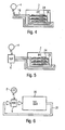
- FIG. 4 shows a liquid-cooled electronic aircraft entertainment system 2.
- Liquid coolant is supplied to the aircraft entertainment system 2 via a connection 4 and a line 18.
- a plurality of electronic assemblies 24 are disposed on a plate-shaped heat exchanger 26 through which cooling liquid flows.
- a liquid coolant can remove a substantially greater quantity of heat from the aircraft entertainment system 2, so that the lines 18 can have a smaller cross section. If the electronic aircraft entertainment system 2 is cooled with a liquid coolant, any desired cooling arrangement which is described in DE 10 2006 041 788.7 can be used.
- FIG. 5 shows a further embodiment of a liquid-cooled electronic aircraft entertainment system.
- This embodiment comprises, in addition to the embodiment of Figure 4 , a heat exchanger 6 which delivers the heat of the internal coolant to the external coolant.
- the external coolant flows through a connection 4 into the heat exchanger 6.
- the external coolant can be liquid or gaseous.
- the internal coolant can be within a temperature range which is different to that of the external coolant, thereby ensuring that the electronic components of the aircraft entertainment system 2 are always within an optimum temperature range and high temperature gradients in the aircraft entertainment system are prevented.
- a pump which is responsible for forced convection can be provided in the circuit of the internal coolant. Any desired arrangement which is described in DE 10 2006 041 788.7 can also be used to cool the electronic components or assemblies of the aircraft entertainment system 2 in this embodiment.
- the pump, the heat exchanger 6 and the connection 4 can be formed integrally as a unit. This unit can be disposed in the aircraft entertainment system 2.
- the cooling of an aircraft entertainment system 2 with a closed circuit of the internal coolant can be tested independently of the cooling system of the aircraft. Moreover, no dirt can be transferred between the external and the internal coolant.
- This aircraft entertainment system 2 with the heat exchanger 6 and the connection 4 can also be replaced particularly easily.
- Figure 6 shows an embodiment of the invention in which the external coolant is constantly in the liquid state.
- the external coolant circulates in a closed circuit 22.
- a liquid cooling system 20 cools the external coolant.
- the external coolant absorbs the heat which is generated by the aircraft entertainment system 2 via a heat exchanger 6.
- a liquid cooling system 20 If a liquid cooling system 20 is used, the mass of the aircraft increases to a lesser extent when compared with a conventional cooling system which supplies cold air to the aircraft entertainment system 2 which is to be cooled or the heat exchanger 6.
- the external coolant is liquid
- pipelines having a smaller cross section can be used, as distinctly larger quantities of heat can be transported away with a liquid coolant than with a gaseous coolant. The space required for cooling is as a result also reduced.
- the coolant lines of a liquid-based cooling system can be installed in the aircraft with greater flexibility, i.e. with fewer restrictions, and also supply with a high cooling capacity locations which could not be supplied with such a high cooling capacity by a conventional cooling system.
- the external coolant is liquid
- the previously described improvement in efficiency results in a lower power consumption for cooling the aircraft entertainment system and therefore the entire aircraft.
- the external coolant can be gaseous or liquid.
- the electronic aircraft entertainment system 2 and the circuit with the internal coolant can be formed as described on connection with Figures 1 to 3 , with the closed cooling circuit according to Figures 2 and 3 being preferred. If a liquid internal coolant is used, the electronic aircraft entertainment system 2 and the circuit with the internal coolant can be formed as described in connection with Figures 4 to 5 .
- the liquid cooling system can be a central or decentralised liquid cooling system.
- Figure 7 shows an embodiment in which the external coolant 6 is cooled by an adsorption cooling system.
- the external coolant flows through the heat exchanger 6 in order to absorb from the internal coolant the heat which is generated by the aircraft entertainment system 2.
- the internal coolant can be gaseous or liquid, the internal coolant can flow in a closed circuit and/or the aircraft entertainment system 2 can be cooled as was described with regard to Figures 1 to 5 .
- An adsorption cooling system 28 can be used as a local cooling system which is independent during flight. However it is also possible for a central adsorption cooling system to be provided.
- FIG 8 shows an embodiment in which the external coolant is fresh water.
- the external coolant flows from a fresh water container 30 via a heat exchanger 6 to a waste water container 32.
- the external coolant absorbs the heat of the internal coolant which is generated by the electronic aircraft entertainment system 2.
- the electronic aircraft entertainment system 2 can be formed and cooled as was described with regard to Figures 1 to 5 . After the water has flowed through the heat exchanger 6, the water can also flow into a hot water container. This type of cooling can be provided as emergency cooling, for example.
- the fresh water can also be used to directly cool the electronic components or assemblies of the aircraft entertainment system 2 by opening the circuit of the internal coolant through valves, for example.
- FIG. 9 shows a further embodiment of the invention in which a liquid external coolant flows through a cooling circuit 34 with the heat exchanger 6 and the liquid cooling system 20.
- a liquid external coolant flows through a cooling circuit 34 with the heat exchanger 6 and the liquid cooling system 20.
- water can be supplied as external coolant from the water system 38 of the aircraft via a valve 36, so that substantially the original quantity of liquid external coolant can be re-established.
- the valve 36 can be actuated automatically, even during flight.
- Figure 10 shows a further embodiment of the invention in which a liquid internal coolant flows through the heat exchanger 6 and the plate-shaped heat exchanger 26 to cool the electronic assembles 24 of an electronic aircraft entertainment system 2.
- the valve 36 can be opened in order to remove water from the water system 38 of the aircraft to replenish the internal coolant.
- the valve 36 can be actuated automatically, even during flight.
- FIG 11 shows a cooling system which does not form part of the present invention and in which a Peltier element 40 replaces the heat exchanger.
- a temperature difference is produced through applying an electrical voltage and the associated flow of current. This temperature difference can be used to cool a medium.
- the Peltier element 40 cools the internal coolant, which was heated upon cooling the electronic aircraft entertainment system 2.
- the electronic aircraft electronic system 2 and the cooling thereof can be formed as was described with regard to Figures 1 to 5 .
- a Peltier element or a plurality of Peltier elements can be disposed in the circuit of the internal coolant.
- the other side of the Peltier element can be disposed outside of the circuit of the internal coolant and deliver the heat to the environment or a coolant by means of a cooling body.
- a Peltier element can also supply a liquid internal coolant with cold and a Peltier element can consequently also be used in conjunction with the embodiments which are depicted in Figures 4 and 5 .
- Figure 12 is a cooling system which does not form part of the present invention and in which the internal coolant for cooling the electronic aircraft entertainment system 2 is cooled by a refrigerating machine 42, a so-called air chiller.
- the refrigerating machine 42 comprises a compressor, a condenser and an evaporator.
- the refrigerating machine can, for example, be formed as a local, decentralised refrigerating machine.
- the external coolant changes its state from gaseous to liquid and vice versa in a closed circuit.
- the electronic aircraft entertainment system 2 can in this respect be composed and cooled as was described in connection with Figures 1 to 3 if the internal coolant is gaseous. If the internal coolant is liquid, the aircraft entertainment system 2 can be composed and cooled as was described in connection with Figures 4 and 5 .
- One advantage of the present invention is that, on account of the closed circuit of the internal coolant, no dirt can enter the aircraft electronic system.
- the internal coolant As a result of separating the external coolant from the internal coolant by means of the heat exchanger 6, which is responsible for a heat transfer between the external and the internal coolant, it is possible for the internal coolant to have a temperature range which is optimum for the electronic components and assemblies. High temperature gradients in the aircraft electronic system can as a result also be prevented. Moreover, the precipitation of condensation water is prevented due to the closed circuit of the internal coolant.
- the cooling of the aircraft electronic system is independent of the air-conditioning system of the aircraft. The described type of cooling of the aircraft electronic system produces less noise than conventional electronic cooling systems.
- the comfort of an air passenger is not reduced.
- the external coolant is liquid
- the previously described improvement in efficiency results in a lower power consumption for cooling the aircraft electronic system and therefore the entire aircraft.
- the air-conditioning system which is used for the air conditioning of the cabin can therefore be of a smaller design, which entails an additional weight saving.
Landscapes
- Engineering & Computer Science (AREA)
- Microelectronics & Electronic Packaging (AREA)
- Physics & Mathematics (AREA)
- Thermal Sciences (AREA)
- Health & Medical Sciences (AREA)
- General Health & Medical Sciences (AREA)
- Pulmonology (AREA)
- Aviation & Aerospace Engineering (AREA)
- Cooling Or The Like Of Electrical Apparatus (AREA)
- Sorption Type Refrigeration Machines (AREA)
Abstract
Claims (14)
- Système de refroidissement à étages multiples pour un système électronique (2) d'aéronef comprenant un circuit interne qui est thermiquement couplé à au moins un composant électronique du système électronique d'aéronef et dans lequel un fluide de refroidissement interne (14) circule en fonctionnement normal afin de transporter de la chaleur de l'au moins un composant électronique jusqu'à un échangeur de chaleur (6), dans lequel l'échangeur de chaleur (6) est adapté à délivrer la chaleur qu'il reçoit du fluide de refroidissement interne (14) à un liquide de refroidissement externe qui circule d'une source à l'extérieur du système électronique (2) d'aéronef à travers l'échangeur de chaleur (6) jusqu'à un dissipateur à l'extérieur du système électronique (2) d'aéronef, dans lequel le circuit interne est configuré de telle manière que le fluide de refroidissement interne (14) s'écoule de l'échangeur de chaleur (6) dans la direction de l'au moins un composant électronique, caractérisé en ce que le circuit (22) dans lequel le liquide de refroidissement externe circule peut être connecté par une troisième soupape (36) à un système d'eau (38) de l'aéronef afin de remplacer au moins partiellement le liquide de refroidissement externe par de l'eau, si nécessaire, pendant le fonctionnement du système électronique (2) d'aéronef.
- Système de refroidissement à étages multiples pour un système électronique (2) d'aéronef comprenant un circuit interne qui est thermiquement couplé à au moins un composant électronique du système électronique d'aéronef et dans lequel un fluide de refroidissement interne (14) circule en fonctionnement normal afin de transporter de la chaleur de l'au moins un composant électronique jusqu'à un échangeur de chaleur (6), dans lequel l'échangeur de chaleur (6) est adapté à délivrer la chaleur qu'il reçoit par le fluide de refroidissement interne (14) à un fluide de refroidissement externe qui s'écoule et/ou circule d'une source à l'extérieur du système électronique (2) d'aéronef à travers l'échangeur de chaleur (6) jusqu'à un dissipateur à l'extérieur du système électronique (2) d'aéronef, dans lequel le circuit interne est configuré de telle manière que le fluide de refroidissement interne (14) s'écoule de l'échangeur de chaleur (6) dans la direction de l'au moins un composant électronique, caractérisé en ce que le circuit interne du fluide de refroidissement interne (14) est connecté par une première soupape (5a) à une ligne d'alimentation, par laquelle un fluide de refroidissement additionnel (14a) est amené de l'extérieur jusqu'au circuit interne, lorsque la première soupape (5a) est ouverte.
- Système de refroidissement à étages multiples pour un système électronique (2) d'aéronef selon la revendication 2,
caractérisé par une deuxième soupape (5b) disposée dans le circuit interne, dans lequel, dans la position ouverte de la deuxième soupape (5b), le fluide de refroidissement peut sortir du circuit interne. - Système de refroidissement à étages multiples pour un système électronique (2) d'aéronef selon l'une quelconque des revendications 1 à 3,
caractérisé en ce que le circuit interne est thermiquement couplé à une pluralité de composants électroniques, de sorte que le fluide de refroidissement interne (14) refroidit une pluralité de composants électroniques. - Système de refroidissement à étages multiples pour un système électronique (2) d'aéronef selon l'une quelconque des revendications 1 à 4,
caractérisé en ce que le fluide de refroidissement interne (14) est gazeux. - Système de refroidissement à étages multiples pour un système électronique (2) d'aéronef selon l'une quelconque des revendications 1 à 4,
caractérisé en ce que le fluide de refroidissement interne (14) est liquide. - Système de refroidissement à étages multiples pour un système électronique (2) d'aéronef selon l'une quelconque des revendications 1 à 6,
caractérisé en ce que le circuit interne est configuré de telle manière que le fluide de refroidissement interne (14) circule sur la base d'une convection naturelle. - Système de refroidissement à étages multiples pour un système électronique (2) d'aéronef selon l'une quelconque des revendications 1 à 6,
caractérisé en ce que le circuit interne est configuré de telle manière que le fluide de refroidissement interne (14) circule sur la base d'une convection forcée. - Système de refroidissement à étages multiples pour un système électronique (2) d'aéronef selon l'une quelconque des revendications 1 à 8,
caractérisé en ce que le fluide de refroidissement externe circule dans un circuit (22) qui est connecté à un système de refroidissement de liquide (20) afin de refroidir le fluide de refroidissement externe. - Système de refroidissement à étages multiples pour un système électronique (2) d'aéronef selon l'une quelconque des revendications 1 à 4 ou 6 à 9,
caractérisé en ce que le circuit interne dans lequel le liquide de refroidissement interne (14) circule peut être connecté par une quatrième soupape (36) à un système d'eau (38) de l'aéronef afin de remplacer au moins partiellement le liquide de refroidissement interne (14) par de l'eau, si nécessaire, pendant le fonctionnement du système électronique (2) d'aéronef. - Système de refroidissement à étages multiples pour un système électronique (2) d'aéronef selon la revendication 1 ou 10, dans lequel des additifs sont mélangés avec l'eau qui remplace le fluide de refroidissement interne et/ou externe.
- Système de refroidissement à étages multiples pour un système électronique (2) d'aéronef selon l'une quelconque des revendications 1 à 11,
caractérisé en ce que l'échangeur de chaleur (6) est connecté à un système de refroidissement par adsorption (28) afin de refroidir le fluide de refroidissement externe au moyen du système de refroidissement par adsorption (28). - Système de refroidissement à étages multiples pour un système électronique (2) d'aéronef selon l'une quelconque des revendications 1 à 11,
caractérisé en ce que le fluide de refroidissement externe est de l'eau douce (30). - Système de refroidissement à étages multiples pour un système électronique (2) d'aéronef selon l'une quelconque des revendications 2 à 8,
caractérisé en ce que le fluide de refroidissement externe est gazeux.
Applications Claiming Priority (5)
| Application Number | Priority Date | Filing Date | Title |
|---|---|---|---|
| US86645306P | 2006-11-20 | 2006-11-20 | |
| DE200610054560 DE102006054560A1 (de) | 2006-11-20 | 2006-11-20 | Kühlsystem und Verfahren zur Kühlung einer Flugzeugeinrichtung |
| US91436207P | 2007-04-27 | 2007-04-27 | |
| DE200710020037 DE102007020037B4 (de) | 2007-04-27 | 2007-04-27 | Kühlanordnung zum Kühlen einer elektronischen Einrichtung eines Luftfahrzeuges |
| PCT/EP2007/010049 WO2008061712A1 (fr) | 2006-11-20 | 2007-11-20 | Circuit de refroidissement multi-étages pour composants électroniques d'un aéronef |
Publications (2)
| Publication Number | Publication Date |
|---|---|
| EP2081824A1 EP2081824A1 (fr) | 2009-07-29 |
| EP2081824B1 true EP2081824B1 (fr) | 2011-10-12 |
Family
ID=39080635
Family Applications (2)
| Application Number | Title | Priority Date | Filing Date |
|---|---|---|---|
| EP07846695A Not-in-force EP2081824B1 (fr) | 2006-11-20 | 2007-11-20 | Circuit de refroidissement multi-étages pour composants électroniques d'un aéronef |
| EP07819875A Not-in-force EP2081825B1 (fr) | 2006-11-20 | 2007-11-20 | Système de refroidissement et procédé pour le refroidissement d'eau potable dans un aéronef |
Family Applications After (1)
| Application Number | Title | Priority Date | Filing Date |
|---|---|---|---|
| EP07819875A Not-in-force EP2081825B1 (fr) | 2006-11-20 | 2007-11-20 | Système de refroidissement et procédé pour le refroidissement d'eau potable dans un aéronef |
Country Status (5)
| Country | Link |
|---|---|
| US (3) | US8438865B2 (fr) |
| EP (2) | EP2081824B1 (fr) |
| JP (2) | JP2010510116A (fr) |
| CA (2) | CA2669180A1 (fr) |
| WO (2) | WO2008061713A1 (fr) |
Families Citing this family (16)
| Publication number | Priority date | Publication date | Assignee | Title |
|---|---|---|---|---|
| US20100011781A1 (en) * | 2008-07-21 | 2010-01-21 | Lents Charles E | Heat exchanger assembly for an aircraft control |
| FR2935131B1 (fr) * | 2008-08-21 | 2011-03-25 | Airbus France | Systeme de refroidissement d'equipements electriques ou electroniques d'une aeronef |
| US20100084118A1 (en) * | 2008-08-21 | 2010-04-08 | Airbus Operations | Cooling system for aircraft electric or electronic devices |
| FR2935132B1 (fr) * | 2008-08-21 | 2011-03-25 | Airbus France | Systeme de refroidissement d'equipements electriques ou electroniques d'un aeronef |
| DE102008044645B3 (de) * | 2008-08-27 | 2010-02-18 | Airbus Deutschland Gmbh | Flugzeugsignalrechnersystem mit einer Mehrzahl von modularen Signalrechnereinheiten |
| FR2972893B1 (fr) | 2011-03-14 | 2013-04-26 | Converteam Technology Ltd | Dispositif de conversion d'energie, notamment pour un systeme d'entrainement electrique de station sous-marine de compression et de pompage |
| US8701426B2 (en) * | 2011-04-28 | 2014-04-22 | Lockheed Martin Corporation | Enhanced boiler |
| FR2986905B1 (fr) * | 2012-02-09 | 2014-02-28 | Snecma | Procede de refroidissement de composants electroniques dans un turboreacteur d'aeronef |
| EP2653386B1 (fr) * | 2012-04-17 | 2014-12-10 | Airbus Operations GmbH | Dissipation de chaleur de l'électronique d'alimentation d'une unité de refroidissement |
| US8934246B1 (en) * | 2013-01-04 | 2015-01-13 | James Nelson Keig | Modular motor control unit for marine use |
| WO2014137422A1 (fr) * | 2013-03-08 | 2014-09-12 | Rolls-Royce North Americantechnologies, Inc. | Avion et système d'alimentation en électricité d'une charge électrique d'avion |
| CN104144592B (zh) * | 2013-05-09 | 2016-12-07 | 鸿富锦精密工业(深圳)有限公司 | 散热系统及设有该散热系统的机柜式服务器 |
| US20140352913A1 (en) * | 2013-05-31 | 2014-12-04 | Hamilton Sundstrand Corporation | Aircraft refrigeration unit evaporator heater |
| CN103662108B (zh) * | 2013-11-20 | 2015-08-12 | 上海宇航系统工程研究所 | 一种模拟太空粉尘环境的试验装置及其方法 |
| US9832910B2 (en) * | 2014-08-12 | 2017-11-28 | Hamilton Sundstrand Corporation | Ram air fan and power electronics cooling systems |
| CN115367118B (zh) * | 2022-08-22 | 2025-12-05 | 上海时的科技有限公司 | 一种倾转旋翼飞行器热管理系统 |
Family Cites Families (41)
| Publication number | Priority date | Publication date | Assignee | Title |
|---|---|---|---|---|
| US3387648A (en) * | 1967-02-23 | 1968-06-11 | Navy Usa | Cabinet enclosed recirculation cooling system carried on extensible chassis mountingelectronic modules |
| US3842460A (en) * | 1972-03-27 | 1974-10-22 | H Wulf | Hydraulic windshield wiper actuating mechanism |
| US4210102A (en) * | 1978-11-17 | 1980-07-01 | Dosmann Joseph B | Space heater heat recovery system |
| US4739823A (en) | 1984-11-09 | 1988-04-26 | Mcdonnell Douglas | Heat exchanger structure |
| DE3812739C1 (fr) | 1988-04-16 | 1989-07-06 | Deutsche Lufthansa Ag, 5000 Koeln, De | |
| US5477706A (en) * | 1991-11-19 | 1995-12-26 | Rocky Research | Heat transfer apparatus and methods for solid-vapor sorption systems |
| FR2646500B1 (fr) | 1989-04-27 | 1994-11-25 | Alsthom Gec | Procede de refroidissement de composants electriques, dispositif pour la mise en oeuvre de ce procede et application aux composants embarques dans un vehicule |
| DE4105034A1 (de) | 1991-02-19 | 1992-08-20 | Klaus G Prof Dipl I Plassmeier | Kuehlcontainer |
| JP2968079B2 (ja) * | 1991-03-29 | 1999-10-25 | 株式会社日立製作所 | マルチタイプ吸収式空調システム |
| EP0577869B1 (fr) * | 1992-07-06 | 1997-01-08 | ZEO-TECH Zeolith Technologie GmbH | Système frigorifique avec un conduit collecteur étanche travaillant sous vide pour la vapeur du fluide de travail |
| US5653111A (en) | 1993-07-07 | 1997-08-05 | Hydrocool Pty. Ltd. | Thermoelectric refrigeration with liquid heat exchange |
| DE4327444A1 (de) | 1993-08-14 | 1995-02-16 | Indramat Gmbh | Kühleinrichtung für einen Schaltschrank |
| DE4340316C2 (de) | 1993-11-26 | 1996-03-21 | Daimler Benz Aerospace Airbus | Anordnung zur Kühlung von Lebensmitteln in einem Flugzeug |
| DE4340317C2 (de) | 1993-11-26 | 1996-03-21 | Daimler Benz Aerospace Airbus | Kühlsystem zur Kühlung von Lebensmitteln in einem Flugzeug |
| US5507150A (en) | 1994-02-04 | 1996-04-16 | Texas Instruments Incorporated | Expendable liquid thermal management system |
| JPH08254369A (ja) | 1995-03-17 | 1996-10-01 | Nippondenso Co Ltd | 吸着式冷凍装置 |
| US6205803B1 (en) * | 1996-04-26 | 2001-03-27 | Mainstream Engineering Corporation | Compact avionics-pod-cooling unit thermal control method and apparatus |
| MY115676A (en) * | 1996-08-06 | 2003-08-30 | Advantest Corp | Printed circuit board with electronic devices mounted thereon |
| RU2127212C1 (ru) | 1997-11-21 | 1999-03-10 | Закрытое акционерное общество "Отделение морских систем ОКБ им.П.О.Сухого" | Способ охлаждения бортовых систем летательного аппарата |
| DE19811719A1 (de) | 1998-03-18 | 1999-09-23 | Alstom Lhb Gmbh | Kühleinrichtung zum Kühlen von Schaltschränken oder Bauteilen in Schienenfahrzeugen |
| JP4583530B2 (ja) * | 1999-03-19 | 2010-11-17 | オルガノ株式会社 | 熱交換用水及びその供給装置 |
| US6530420B1 (en) * | 1999-09-17 | 2003-03-11 | Sanyo Electric Co., Ltd. | Heat carrier |
| DE10009521A1 (de) | 2000-02-29 | 2001-08-30 | Mannesmann Sachs Ag | Elektrisches System |
| EP1158389A3 (fr) | 2000-05-25 | 2002-11-13 | Kioan Cheon | Ordinateur possédant un dispositif de refroidissement et échangeur de chaleur de ce dispositif de refroidissement |
| FR2820196B1 (fr) | 2001-01-29 | 2006-12-29 | Claude Antoine Blaizat | Procede de maintien sous froid des trolleys a bord des avions assurant aussi le chauffage ou le maintien a chaud ainsi que l'ensemble du dispositif correspondant |
| US6993923B2 (en) * | 2001-10-05 | 2006-02-07 | Rich Beers Marine, Inc. | Load bank |
| JP4199018B2 (ja) | 2003-02-14 | 2008-12-17 | 株式会社日立製作所 | ラックマウントサーバシステム |
| TW200416983A (en) * | 2003-02-26 | 2004-09-01 | Advanced Semiconductor Eng | Package structure with a cooling system |
| DE20308158U1 (de) | 2003-03-07 | 2003-07-31 | Rittal GmbH & Co. KG, 35745 Herborn | Flüssigkeits-Kühlsystem |
| DE10332770A1 (de) | 2003-07-17 | 2005-02-24 | Jürgen Dr.-Ing. Schulz-Harder | Kühlvorrichtung zum Abführen von Verlustwärme von einem elektrischen oder elektronischen Bauelement oder Baugruppe |
| US7311817B2 (en) * | 2003-11-14 | 2007-12-25 | Semler Industries, Inc. | System and method for sanitizing and refilling a potable water system onboard a transport vehicle |
| US7231778B2 (en) * | 2004-03-29 | 2007-06-19 | Be Intellectual Property, Inc. | Cooling system for a commercial aircraft galley |
| US7281388B2 (en) * | 2004-03-31 | 2007-10-16 | Intel Corporation | Apparatus to use a refrigerator in mobile computing device |
| DE102004020642A1 (de) | 2004-04-22 | 2005-11-10 | Höhne, Sven, Dipl.-Ing (FH) | Schwerkraftkühlung für elektronische Bauteile |
| US7581698B2 (en) * | 2004-04-23 | 2009-09-01 | Airbus Deutschland Gmbh | Method and apparatus for tempering gaseous and/or liquid media in transportation vehicles, particularly in aircraft |
| DE102004019790B4 (de) | 2004-04-23 | 2006-07-20 | Airbus Deutschland Gmbh | Vorrichtung zur nahezu verzögerungsfreien Temperierung von gasförmigen und/oder flüssigen Medien in einem Verkehrsmittel, insbesondere in einem Luftfahrzeug |
| DE102005015718A1 (de) | 2005-03-31 | 2006-10-05 | Robert Bosch Gmbh | Kühlanordnung für ein elektrisches Steuergerät |
| US20070051166A1 (en) * | 2005-09-02 | 2007-03-08 | Baker Kenneth R | Leak detection systems and methods |
| US8720217B2 (en) * | 2006-07-10 | 2014-05-13 | Mag Aerospace Industries, Inc. | Galley cooling heat sink through water system |
| DE102006041788B4 (de) | 2006-09-06 | 2012-06-14 | Airbus Operations Gmbh | Luftfahrzeug-Elektronikkühleinrichtung für ein Luftfahrzeug mit einem Flüssigkeitskühlsystem |
| DE102006054560A1 (de) | 2006-11-20 | 2008-05-21 | Airbus Deutschland Gmbh | Kühlsystem und Verfahren zur Kühlung einer Flugzeugeinrichtung |
-
2007
- 2007-11-20 CA CA002669180A patent/CA2669180A1/fr not_active Abandoned
- 2007-11-20 US US12/514,742 patent/US8438865B2/en not_active Expired - Fee Related
- 2007-11-20 WO PCT/EP2007/010050 patent/WO2008061713A1/fr not_active Ceased
- 2007-11-20 US US12/514,731 patent/US20100044016A1/en not_active Abandoned
- 2007-11-20 EP EP07846695A patent/EP2081824B1/fr not_active Not-in-force
- 2007-11-20 EP EP07819875A patent/EP2081825B1/fr not_active Not-in-force
- 2007-11-20 JP JP2009536674A patent/JP2010510116A/ja active Pending
- 2007-11-20 JP JP2009536675A patent/JP2010510117A/ja active Pending
- 2007-11-20 CA CA002668663A patent/CA2668663A1/fr not_active Abandoned
- 2007-11-20 WO PCT/EP2007/010049 patent/WO2008061712A1/fr not_active Ceased
-
2013
- 2013-10-24 US US14/062,300 patent/US9451732B2/en not_active Expired - Fee Related
Also Published As
| Publication number | Publication date |
|---|---|
| US20100044016A1 (en) | 2010-02-25 |
| WO2008061713A1 (fr) | 2008-05-29 |
| US9451732B2 (en) | 2016-09-20 |
| CA2668663A1 (fr) | 2008-05-29 |
| EP2081825B1 (fr) | 2011-06-22 |
| WO2008061712A1 (fr) | 2008-05-29 |
| JP2010510116A (ja) | 2010-04-02 |
| CA2669180A1 (fr) | 2008-05-29 |
| JP2010510117A (ja) | 2010-04-02 |
| US20100051237A1 (en) | 2010-03-04 |
| EP2081825A1 (fr) | 2009-07-29 |
| EP2081824A1 (fr) | 2009-07-29 |
| US8438865B2 (en) | 2013-05-14 |
| US20140146469A1 (en) | 2014-05-29 |
Similar Documents
| Publication | Publication Date | Title |
|---|---|---|
| EP2081824B1 (fr) | Circuit de refroidissement multi-étages pour composants électroniques d'un aéronef | |
| US7920382B2 (en) | Aircraft electronics cooling apparatus for an aircraft having a liquid cooling system | |
| RU2457983C2 (ru) | Многоступенчатая система охлаждения электронных компонентов воздушного судна | |
| US9752834B2 (en) | Redundant integrated liquid cooling system for avionics | |
| US10800535B2 (en) | Integrated environmental control systems and methods for controlling environmental temperature of an enclosed space | |
| CN103079956B (zh) | 包括分离的制冷循环的飞行器空气调节系统 | |
| RU2420428C2 (ru) | Система охлаждения | |
| US20100084118A1 (en) | Cooling system for aircraft electric or electronic devices | |
| US20080053126A1 (en) | Aircraft Air-Conditioning System For The Individual Air Conditioning Of Regions Of An Aircraft Cabin With A Liquid Coolant | |
| CA2772268C (fr) | Systeme et procede de refroidissement d'au moins un dispositif produisant de la chaleur dans un avion | |
| KR20230098622A (ko) | 배터리 구동 차량용 냉각기가 있는 히트 펌프 어셈블리 및 히트 펌프 어셈블리 작동 방법 | |
| EP2004487B1 (fr) | Systeme de refroidissement et arrangement contenant un systeme de refroidissement et un conteneur de fret | |
| CN101155728A (zh) | 使用循环空气进行货舱空气调节的系统和方法 | |
| US20130111938A1 (en) | Heat exchanger, cooling system and method for operating a heat exchanger and a cooling system | |
| CN104507804A (zh) | 飞行器厨房制冷系统 | |
| US20180086469A1 (en) | Space-optimized cooling system for a galley, and method of operating such a cooling system | |
| US9272788B2 (en) | Aircraft cooling system and method for operating an aircraft cooling system | |
| CN101547832B (zh) | 飞机电子部件的多级冷却 | |
| CN103373469B (zh) | 飞行器热控制系统、操作热控制系统的方法以及飞行器 | |
| DE102007020037B4 (de) | Kühlanordnung zum Kühlen einer elektronischen Einrichtung eines Luftfahrzeuges | |
| BRPI0719043A2 (pt) | Sistema de resfriamento de multiestágio para um sistema eletrônico de aeronave | |
| JP2002127994A (ja) | 空調装置 |
Legal Events
| Date | Code | Title | Description |
|---|---|---|---|
| PUAI | Public reference made under article 153(3) epc to a published international application that has entered the european phase |
Free format text: ORIGINAL CODE: 0009012 |
|
| 17P | Request for examination filed |
Effective date: 20090512 |
|
| AK | Designated contracting states |
Kind code of ref document: A1 Designated state(s): AT BE BG CH CY CZ DE DK EE ES FI FR GB GR HU IE IS IT LI LT LU LV MC MT NL PL PT RO SE SI SK TR |
|
| DAX | Request for extension of the european patent (deleted) | ||
| 17Q | First examination report despatched |
Effective date: 20100528 |
|
| GRAP | Despatch of communication of intention to grant a patent |
Free format text: ORIGINAL CODE: EPIDOSNIGR1 |
|
| GRAS | Grant fee paid |
Free format text: ORIGINAL CODE: EPIDOSNIGR3 |
|
| RAP1 | Party data changed (applicant data changed or rights of an application transferred) |
Owner name: AIRBUS OPERATIONS GMBH |
|
| GRAA | (expected) grant |
Free format text: ORIGINAL CODE: 0009210 |
|
| AK | Designated contracting states |
Kind code of ref document: B1 Designated state(s): AT BE BG CH CY CZ DE DK EE ES FI FR GB GR HU IE IS IT LI LT LU LV MC MT NL PL PT RO SE SI SK TR |
|
| REG | Reference to a national code |
Ref country code: GB Ref legal event code: FG4D |
|
| REG | Reference to a national code |
Ref country code: CH Ref legal event code: EP |
|
| REG | Reference to a national code |
Ref country code: IE Ref legal event code: FG4D |
|
| REG | Reference to a national code |
Ref country code: DE Ref legal event code: R096 Ref document number: 602007017871 Country of ref document: DE Effective date: 20111208 |
|
| REG | Reference to a national code |
Ref country code: NL Ref legal event code: VDEP Effective date: 20111012 |
|
| LTIE | Lt: invalidation of european patent or patent extension |
Effective date: 20111012 |
|
| REG | Reference to a national code |
Ref country code: AT Ref legal event code: MK05 Ref document number: 528211 Country of ref document: AT Kind code of ref document: T Effective date: 20111012 |
|
| PG25 | Lapsed in a contracting state [announced via postgrant information from national office to epo] |
Ref country code: BE Free format text: LAPSE BECAUSE OF FAILURE TO SUBMIT A TRANSLATION OF THE DESCRIPTION OR TO PAY THE FEE WITHIN THE PRESCRIBED TIME-LIMIT Effective date: 20111012 Ref country code: IS Free format text: LAPSE BECAUSE OF FAILURE TO SUBMIT A TRANSLATION OF THE DESCRIPTION OR TO PAY THE FEE WITHIN THE PRESCRIBED TIME-LIMIT Effective date: 20120212 Ref country code: LT Free format text: LAPSE BECAUSE OF FAILURE TO SUBMIT A TRANSLATION OF THE DESCRIPTION OR TO PAY THE FEE WITHIN THE PRESCRIBED TIME-LIMIT Effective date: 20111012 |
|
| PG25 | Lapsed in a contracting state [announced via postgrant information from national office to epo] |
Ref country code: SE Free format text: LAPSE BECAUSE OF FAILURE TO SUBMIT A TRANSLATION OF THE DESCRIPTION OR TO PAY THE FEE WITHIN THE PRESCRIBED TIME-LIMIT Effective date: 20111012 Ref country code: LV Free format text: LAPSE BECAUSE OF FAILURE TO SUBMIT A TRANSLATION OF THE DESCRIPTION OR TO PAY THE FEE WITHIN THE PRESCRIBED TIME-LIMIT Effective date: 20111012 Ref country code: SI Free format text: LAPSE BECAUSE OF FAILURE TO SUBMIT A TRANSLATION OF THE DESCRIPTION OR TO PAY THE FEE WITHIN THE PRESCRIBED TIME-LIMIT Effective date: 20111012 Ref country code: PT Free format text: LAPSE BECAUSE OF FAILURE TO SUBMIT A TRANSLATION OF THE DESCRIPTION OR TO PAY THE FEE WITHIN THE PRESCRIBED TIME-LIMIT Effective date: 20120213 Ref country code: GR Free format text: LAPSE BECAUSE OF FAILURE TO SUBMIT A TRANSLATION OF THE DESCRIPTION OR TO PAY THE FEE WITHIN THE PRESCRIBED TIME-LIMIT Effective date: 20120113 Ref country code: NL Free format text: LAPSE BECAUSE OF FAILURE TO SUBMIT A TRANSLATION OF THE DESCRIPTION OR TO PAY THE FEE WITHIN THE PRESCRIBED TIME-LIMIT Effective date: 20111012 |
|
| PG25 | Lapsed in a contracting state [announced via postgrant information from national office to epo] |
Ref country code: MC Free format text: LAPSE BECAUSE OF NON-PAYMENT OF DUE FEES Effective date: 20111130 Ref country code: CY Free format text: LAPSE BECAUSE OF FAILURE TO SUBMIT A TRANSLATION OF THE DESCRIPTION OR TO PAY THE FEE WITHIN THE PRESCRIBED TIME-LIMIT Effective date: 20111012 |
|
| REG | Reference to a national code |
Ref country code: CH Ref legal event code: PL |
|
| PG25 | Lapsed in a contracting state [announced via postgrant information from national office to epo] |
Ref country code: LI Free format text: LAPSE BECAUSE OF NON-PAYMENT OF DUE FEES Effective date: 20111130 Ref country code: EE Free format text: LAPSE BECAUSE OF FAILURE TO SUBMIT A TRANSLATION OF THE DESCRIPTION OR TO PAY THE FEE WITHIN THE PRESCRIBED TIME-LIMIT Effective date: 20111012 Ref country code: CH Free format text: LAPSE BECAUSE OF NON-PAYMENT OF DUE FEES Effective date: 20111130 Ref country code: SK Free format text: LAPSE BECAUSE OF FAILURE TO SUBMIT A TRANSLATION OF THE DESCRIPTION OR TO PAY THE FEE WITHIN THE PRESCRIBED TIME-LIMIT Effective date: 20111012 Ref country code: BG Free format text: LAPSE BECAUSE OF FAILURE TO SUBMIT A TRANSLATION OF THE DESCRIPTION OR TO PAY THE FEE WITHIN THE PRESCRIBED TIME-LIMIT Effective date: 20120112 Ref country code: DK Free format text: LAPSE BECAUSE OF FAILURE TO SUBMIT A TRANSLATION OF THE DESCRIPTION OR TO PAY THE FEE WITHIN THE PRESCRIBED TIME-LIMIT Effective date: 20111012 Ref country code: CZ Free format text: LAPSE BECAUSE OF FAILURE TO SUBMIT A TRANSLATION OF THE DESCRIPTION OR TO PAY THE FEE WITHIN THE PRESCRIBED TIME-LIMIT Effective date: 20111012 |
|
| PLBE | No opposition filed within time limit |
Free format text: ORIGINAL CODE: 0009261 |
|
| STAA | Information on the status of an ep patent application or granted ep patent |
Free format text: STATUS: NO OPPOSITION FILED WITHIN TIME LIMIT |
|
| REG | Reference to a national code |
Ref country code: IE Ref legal event code: MM4A |
|
| PG25 | Lapsed in a contracting state [announced via postgrant information from national office to epo] |
Ref country code: PL Free format text: LAPSE BECAUSE OF FAILURE TO SUBMIT A TRANSLATION OF THE DESCRIPTION OR TO PAY THE FEE WITHIN THE PRESCRIBED TIME-LIMIT Effective date: 20111012 Ref country code: RO Free format text: LAPSE BECAUSE OF FAILURE TO SUBMIT A TRANSLATION OF THE DESCRIPTION OR TO PAY THE FEE WITHIN THE PRESCRIBED TIME-LIMIT Effective date: 20111012 Ref country code: IT Free format text: LAPSE BECAUSE OF FAILURE TO SUBMIT A TRANSLATION OF THE DESCRIPTION OR TO PAY THE FEE WITHIN THE PRESCRIBED TIME-LIMIT Effective date: 20111012 |
|
| 26N | No opposition filed |
Effective date: 20120713 |
|
| PG25 | Lapsed in a contracting state [announced via postgrant information from national office to epo] |
Ref country code: IE Free format text: LAPSE BECAUSE OF NON-PAYMENT OF DUE FEES Effective date: 20111120 |
|
| REG | Reference to a national code |
Ref country code: DE Ref legal event code: R097 Ref document number: 602007017871 Country of ref document: DE Effective date: 20120713 |
|
| PG25 | Lapsed in a contracting state [announced via postgrant information from national office to epo] |
Ref country code: AT Free format text: LAPSE BECAUSE OF FAILURE TO SUBMIT A TRANSLATION OF THE DESCRIPTION OR TO PAY THE FEE WITHIN THE PRESCRIBED TIME-LIMIT Effective date: 20111012 |
|
| PG25 | Lapsed in a contracting state [announced via postgrant information from national office to epo] |
Ref country code: MT Free format text: LAPSE BECAUSE OF FAILURE TO SUBMIT A TRANSLATION OF THE DESCRIPTION OR TO PAY THE FEE WITHIN THE PRESCRIBED TIME-LIMIT Effective date: 20111012 |
|
| PG25 | Lapsed in a contracting state [announced via postgrant information from national office to epo] |
Ref country code: ES Free format text: LAPSE BECAUSE OF FAILURE TO SUBMIT A TRANSLATION OF THE DESCRIPTION OR TO PAY THE FEE WITHIN THE PRESCRIBED TIME-LIMIT Effective date: 20120123 |
|
| PG25 | Lapsed in a contracting state [announced via postgrant information from national office to epo] |
Ref country code: LU Free format text: LAPSE BECAUSE OF NON-PAYMENT OF DUE FEES Effective date: 20111120 |
|
| PG25 | Lapsed in a contracting state [announced via postgrant information from national office to epo] |
Ref country code: FI Free format text: LAPSE BECAUSE OF FAILURE TO SUBMIT A TRANSLATION OF THE DESCRIPTION OR TO PAY THE FEE WITHIN THE PRESCRIBED TIME-LIMIT Effective date: 20111012 |
|
| PG25 | Lapsed in a contracting state [announced via postgrant information from national office to epo] |
Ref country code: TR Free format text: LAPSE BECAUSE OF FAILURE TO SUBMIT A TRANSLATION OF THE DESCRIPTION OR TO PAY THE FEE WITHIN THE PRESCRIBED TIME-LIMIT Effective date: 20111012 |
|
| PG25 | Lapsed in a contracting state [announced via postgrant information from national office to epo] |
Ref country code: HU Free format text: LAPSE BECAUSE OF FAILURE TO SUBMIT A TRANSLATION OF THE DESCRIPTION OR TO PAY THE FEE WITHIN THE PRESCRIBED TIME-LIMIT Effective date: 20111012 |
|
| REG | Reference to a national code |
Ref country code: FR Ref legal event code: PLFP Year of fee payment: 9 |
|
| REG | Reference to a national code |
Ref country code: FR Ref legal event code: PLFP Year of fee payment: 10 |
|
| PGFP | Annual fee paid to national office [announced via postgrant information from national office to epo] |
Ref country code: GB Payment date: 20161122 Year of fee payment: 10 Ref country code: FR Payment date: 20161118 Year of fee payment: 10 Ref country code: DE Payment date: 20161121 Year of fee payment: 10 |
|
| REG | Reference to a national code |
Ref country code: DE Ref legal event code: R119 Ref document number: 602007017871 Country of ref document: DE |
|
| GBPC | Gb: european patent ceased through non-payment of renewal fee |
Effective date: 20171120 |
|
| REG | Reference to a national code |
Ref country code: FR Ref legal event code: ST Effective date: 20180731 |
|
| PG25 | Lapsed in a contracting state [announced via postgrant information from national office to epo] |
Ref country code: DE Free format text: LAPSE BECAUSE OF NON-PAYMENT OF DUE FEES Effective date: 20180602 Ref country code: FR Free format text: LAPSE BECAUSE OF NON-PAYMENT OF DUE FEES Effective date: 20171130 |
|
| PG25 | Lapsed in a contracting state [announced via postgrant information from national office to epo] |
Ref country code: GB Free format text: LAPSE BECAUSE OF NON-PAYMENT OF DUE FEES Effective date: 20171120 |