EP2082903A2 - Ressort de véhicule en matière active à fibres composites - Google Patents
Ressort de véhicule en matière active à fibres composites Download PDFInfo
- Publication number
- EP2082903A2 EP2082903A2 EP09000685A EP09000685A EP2082903A2 EP 2082903 A2 EP2082903 A2 EP 2082903A2 EP 09000685 A EP09000685 A EP 09000685A EP 09000685 A EP09000685 A EP 09000685A EP 2082903 A2 EP2082903 A2 EP 2082903A2
- Authority
- EP
- European Patent Office
- Prior art keywords
- spring
- band
- regions
- band spring
- width
- Prior art date
- Legal status (The legal status is an assumption and is not a legal conclusion. Google has not performed a legal analysis and makes no representation as to the accuracy of the status listed.)
- Granted
Links
- 239000002131 composite material Substances 0.000 title claims description 13
- 239000000835 fiber Substances 0.000 claims abstract description 31
- 239000000725 suspension Substances 0.000 claims abstract 3
- 230000002441 reversible effect Effects 0.000 claims description 31
- 238000005452 bending Methods 0.000 claims description 14
- 239000011347 resin Substances 0.000 claims description 6
- 229920005989 resin Polymers 0.000 claims description 6
- 229920006231 aramid fiber Polymers 0.000 claims description 5
- 239000011152 fibreglass Substances 0.000 claims description 5
- 238000011065 in-situ storage Methods 0.000 claims description 3
- 239000004918 carbon fiber reinforced polymer Substances 0.000 claims 4
- 239000011151 fibre-reinforced plastic Substances 0.000 claims 2
- 239000000463 material Substances 0.000 description 17
- 238000010586 diagram Methods 0.000 description 7
- 239000002184 metal Substances 0.000 description 6
- 229920000049 Carbon (fiber) Polymers 0.000 description 4
- 239000004917 carbon fiber Substances 0.000 description 4
- 239000002657 fibrous material Substances 0.000 description 4
- 238000010276 construction Methods 0.000 description 3
- VNWKTOKETHGBQD-UHFFFAOYSA-N methane Chemical compound C VNWKTOKETHGBQD-UHFFFAOYSA-N 0.000 description 3
- 239000000047 product Substances 0.000 description 3
- 238000004904 shortening Methods 0.000 description 3
- 239000004760 aramid Substances 0.000 description 2
- 230000032798 delamination Effects 0.000 description 2
- 239000004744 fabric Substances 0.000 description 2
- 230000002349 favourable effect Effects 0.000 description 2
- 239000003365 glass fiber Substances 0.000 description 2
- 238000004519 manufacturing process Methods 0.000 description 2
- 239000011159 matrix material Substances 0.000 description 2
- 229920000271 Kevlar® Polymers 0.000 description 1
- 230000015572 biosynthetic process Effects 0.000 description 1
- 230000006835 compression Effects 0.000 description 1
- 238000007906 compression Methods 0.000 description 1
- 238000005520 cutting process Methods 0.000 description 1
- 238000004090 dissolution Methods 0.000 description 1
- 230000000694 effects Effects 0.000 description 1
- 210000003746 feather Anatomy 0.000 description 1
- 238000000265 homogenisation Methods 0.000 description 1
- 239000013067 intermediate product Substances 0.000 description 1
- 230000002427 irreversible effect Effects 0.000 description 1
- 239000004761 kevlar Substances 0.000 description 1
- 238000000034 method Methods 0.000 description 1
- 238000012986 modification Methods 0.000 description 1
- 230000004048 modification Effects 0.000 description 1
- 238000005457 optimization Methods 0.000 description 1
- 230000003014 reinforcing effect Effects 0.000 description 1
- 230000000284 resting effect Effects 0.000 description 1
- 238000004804 winding Methods 0.000 description 1
Images


Classifications
-
- B—PERFORMING OPERATIONS; TRANSPORTING
- B60—VEHICLES IN GENERAL
- B60G—VEHICLE SUSPENSION ARRANGEMENTS
- B60G11/00—Resilient suspensions characterised by arrangement, location or kind of springs
-
- B—PERFORMING OPERATIONS; TRANSPORTING
- B60—VEHICLES IN GENERAL
- B60G—VEHICLE SUSPENSION ARRANGEMENTS
- B60G15/00—Resilient suspensions characterised by arrangement, location or type of combined spring and vibration damper, e.g. telescopic type
- B60G15/02—Resilient suspensions characterised by arrangement, location or type of combined spring and vibration damper, e.g. telescopic type having mechanical spring
- B60G15/06—Resilient suspensions characterised by arrangement, location or type of combined spring and vibration damper, e.g. telescopic type having mechanical spring and fluid damper
- B60G15/062—Resilient suspensions characterised by arrangement, location or type of combined spring and vibration damper, e.g. telescopic type having mechanical spring and fluid damper the spring being arranged around the damper
-
- F—MECHANICAL ENGINEERING; LIGHTING; HEATING; WEAPONS; BLASTING
- F16—ENGINEERING ELEMENTS AND UNITS; GENERAL MEASURES FOR PRODUCING AND MAINTAINING EFFECTIVE FUNCTIONING OF MACHINES OR INSTALLATIONS; THERMAL INSULATION IN GENERAL
- F16F—SPRINGS; SHOCK-ABSORBERS; MEANS FOR DAMPING VIBRATION
- F16F1/00—Springs
- F16F1/02—Springs made of steel or other material having low internal friction; Wound, torsion, leaf, cup, ring or the like springs, the material of the spring not being relevant
- F16F1/025—Springs made of steel or other material having low internal friction; Wound, torsion, leaf, cup, ring or the like springs, the material of the spring not being relevant characterised by having a particular shape
- F16F1/027—Planar, e.g. in sheet form; leaf springs
-
- F—MECHANICAL ENGINEERING; LIGHTING; HEATING; WEAPONS; BLASTING
- F16—ENGINEERING ELEMENTS AND UNITS; GENERAL MEASURES FOR PRODUCING AND MAINTAINING EFFECTIVE FUNCTIONING OF MACHINES OR INSTALLATIONS; THERMAL INSULATION IN GENERAL
- F16F—SPRINGS; SHOCK-ABSORBERS; MEANS FOR DAMPING VIBRATION
- F16F15/00—Suppression of vibrations in systems; Means or arrangements for avoiding or reducing out-of-balance forces, e.g. due to motion
- F16F15/02—Suppression of vibrations of non-rotating, e.g. reciprocating systems; Suppression of vibrations of rotating systems by use of members not moving with the rotating systems
- F16F15/022—Suppression of vibrations of non-rotating, e.g. reciprocating systems; Suppression of vibrations of rotating systems by use of members not moving with the rotating systems using dampers and springs in combination
-
- B—PERFORMING OPERATIONS; TRANSPORTING
- B60—VEHICLES IN GENERAL
- B60G—VEHICLE SUSPENSION ARRANGEMENTS
- B60G2202/00—Indexing codes relating to the type of spring, damper or actuator
- B60G2202/10—Type of spring
- B60G2202/11—Leaf spring
-
- B—PERFORMING OPERATIONS; TRANSPORTING
- B60—VEHICLES IN GENERAL
- B60G—VEHICLE SUSPENSION ARRANGEMENTS
- B60G2202/00—Indexing codes relating to the type of spring, damper or actuator
- B60G2202/10—Type of spring
- B60G2202/11—Leaf spring
- B60G2202/116—Leaf spring having a "C" form loaded only at its ends transversally to its central axis
-
- B—PERFORMING OPERATIONS; TRANSPORTING
- B60—VEHICLES IN GENERAL
- B60G—VEHICLE SUSPENSION ARRANGEMENTS
- B60G2202/00—Indexing codes relating to the type of spring, damper or actuator
- B60G2202/10—Type of spring
- B60G2202/14—Plastic spring, e.g. rubber
-
- B—PERFORMING OPERATIONS; TRANSPORTING
- B60—VEHICLES IN GENERAL
- B60G—VEHICLE SUSPENSION ARRANGEMENTS
- B60G2202/00—Indexing codes relating to the type of spring, damper or actuator
- B60G2202/10—Type of spring
- B60G2202/14—Plastic spring, e.g. rubber
- B60G2202/141—Plastic spring, e.g. rubber subjected to tension
-
- B—PERFORMING OPERATIONS; TRANSPORTING
- B60—VEHICLES IN GENERAL
- B60G—VEHICLE SUSPENSION ARRANGEMENTS
- B60G2206/00—Indexing codes related to the manufacturing of suspensions: constructional features, the materials used, procedures or tools
- B60G2206/01—Constructional features of suspension elements, e.g. arms, dampers, springs
- B60G2206/40—Constructional features of dampers and/or springs
- B60G2206/42—Springs
- B60G2206/428—Leaf springs
-
- B—PERFORMING OPERATIONS; TRANSPORTING
- B60—VEHICLES IN GENERAL
- B60G—VEHICLE SUSPENSION ARRANGEMENTS
- B60G2206/00—Indexing codes related to the manufacturing of suspensions: constructional features, the materials used, procedures or tools
- B60G2206/01—Constructional features of suspension elements, e.g. arms, dampers, springs
- B60G2206/70—Materials used in suspensions
- B60G2206/71—Light weight materials
- B60G2206/7101—Fiber-reinforced plastics [FRP]
Definitions
- the invention relates to a band spring made of fiber composite material with wavy course, wherein a spring band meanders as a single wave train of reverse areas and intermediate portions about a longitudinal center line L, which corresponds substantially to the direction of the force K.
- the invention further relates to a band spring made of composite material with a double-wave course, wherein two spring bands as wave trains each meander around two mutually parallel center lines L1, L2, which are parallel to an intermediate longitudinal center line L, which corresponds substantially to the direction of the force.
- Products made of fiber composite material are made of mats of resin-impregnated fabrics or prepregs with specific blank form or resin-impregnated fiber bundles which may be parallel-stranded or twisted into each other (Rowings), which are placed in molds and brought there under pressure to an elevated temperature, in which the matrix-forming resin irreversibly hardens.
- the fiber material in the matrix leads to an increased strength of the finished product.
- the mats mentioned can be superimposed multilayered, whereby also different mat qualities can be used.
- the fiber strands mentioned can be interwoven or interlaced, so that fabric-like structures arise.
- the fibers can be used as glass fibers, as carbon fibers, as aramid fibers (Kevlar) or as metal fibers sorted or mixed with each other.
- the resins used usually harden At temperatures of 150 to 180 ° C irreversible and give the finished product its permanent form.
- a band spring of the former type is from the US Pat. No. 4,927,124 and from the US 5 013 013 A known.
- the band spring in this case has over the entire length of the spring band substantially constant width and constant thickness. It is also described here that two band springs of this type can be used in a symmetrical arrangement in a strut for a motor vehicle.
- band springs of constant width are known in which first reversal regions are increased in relation to the second reversal regions and the connecting intermediate sections in the thickness.
- a compression takes place here first by deforming the respective second of thinner material existing inversion regions, which are thereby highly stressed in a disadvantageous manner. It is the use of two Bandfedem of this type provided with a damper unit in a motor vehicle.
- the present invention seeks to provide Bandfedem that have favorable load conditions in use and thus promise an increased life. It should be possible to use in struts new compact design.
- a first solution consists in a band spring made of fiber composite material with wave-shaped course, wherein a spring band meanders as a single wave train of reverse areas and intermediate sections about a longitudinal center line L, which corresponds in weseritlichen the direction of the force K, wherein in the reversal regions of the wave train in each case an increased resistance moment of the Federbandes provided is.
- the increased resistance moment according to the invention in the reverse areas leads to reduced stresses in these reversal areas when the spring is loaded, so that delamination in these critical areas as a result of shear stresses in the material can be avoided.
- Delamination is understood to mean at least local dissolution of the composite between fiber material and matrix.
- stress peaks on the outside of the reversal areas should be avoided.
- the design of the spring is very compact.
- a second solution consists in a band spring made of fiber composite material with a double-wave course, wherein two spring bands meander as wave trains of reverse areas and intermediate portions about two mutually parallel center lines L1, L2, which are parallel to an intermediate longitudinal center line L, which is substantially the direction of the force K corresponds, wherein the spring strips are connected to each other at first inward reversal regions of the wave trains and in the second outer reversal regions of the wave trains each having an increased resistance moment.
- the cross section of the spring band or the spring bands over the entire length remains substantially constant.
- the increase of the resistance moment in the reversal regions takes place by an increase in the thickness H, which enters into the calculation of the resistance moment with a higher power than the width B.
- the moment of resistance can be increased in the reverse regions, if necessary. Also at substantially constant cross-sectional areas.
- Both the variation of the width of the spring band and the variation of the thickness of the spring band should be carried out substantially continuously or finely graded. While the width variation is essentially due to the shape of the blank of the prepregs used, the thickness variation can be created by incrementally increasing the multi-layered prepregs.
- strip spring is made of several layers, wherein a middle layer of prepregs of lower quality, for example made of fiberglass reinforced resin impregnated material is produced while outer layers of higher quality prepregs, for example, carbon fiber reinforced or aramid fiber reinforced resin impregnated material ,
- the resin-impregnated fiber material enters the spring band of the other wave train uncut from the spring band of one wave train in the region of the inner reversal regions by means of suitable laying techniques, whereby a regular crossover leads to a firm bond.
- the fiber strands can be small Angles run obliquely to the longitudinal direction of the spring strips and thereby cross each other in a regular arrangement.
- the intermediate products formed from prepregs and / or rovings are placed in heatable molds and cured irreversibly under pressure.
- the band springs in the direction of the longitudinal central axis aligned through holes through which a damper assembly can be inserted. These through holes are preferably kept open during the production of the band springs by appropriate cutting of the prepregs and / or by appropriate laying of the rowings. However, they can also be drilled after manufacture.
- the band springs preferably end at both ends in a reversal area.
- the last intermediate section forms a large-area support surface for resting on a shape-matched spring plate.
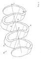
- FIG. 1 shows a strip spring 11 according to the invention in a first embodiment, which comprises a wavy strip spring band which meanders around a longitudinal center line L and has four complete wave units.
- a strip spring 11 which comprises a wavy strip spring band which meanders around a longitudinal center line L and has four complete wave units.
- three complete and two half-cut first reversal regions 12 and four complete second reversal regions 13 can be seen, wherein the half-turn regions define the ends of the band spring 11.
- the more curved return portions 12, 13 are connected by intermediate portions 14, 15 of lesser curvature.
- the material thickness of the spring band is variable, wherein the thickness H and transverse to the wavy line width B of the band spring in the reverse regions 12, 13 is substantially higher than in the connecting portions 14, 15.
- the width changes are hereby largely constant and can a sinusoidal course of the edge lines (when processing the spring band oin a plane) are shown.
- train-pressure-force introduction into the respective outer intermediate portions 14, 15 and the half-cut off reversal regions 12 at the end of the band spring there is a shortening and elongation of the Baridfeder.
- the flexural resistance moments of the reversal regions 12, 13 are due to the increased thickness and width substantially higher than that of the intermediate sections 14, 15.
- possible uniform stress states in the material of the band spring over its entire length are achieved.
- FIG. 2 shows a strip spring 11 according to the invention in a second embodiment, which comprises a spring strip with wave-shaped course, the total of a Mean longitudinal meandered L and has two complete wave units.
- a strip spring 11 according to the invention in a second embodiment, which comprises a spring strip with wave-shaped course, the total of a Mean longitudinal meandered L and has two complete wave units.
- two complete first reversal regions 12 and three complete second reversal regions 13 can be seen, the ends of the band spring 11 no longer forming reversal regions.
- the more curved return portions 12, 13 are connected by intermediate portions 14, 15 of lesser curvature.
- the material thickness of the spring band is variable, wherein the thickness H in the reverse regions 12, 13 is greater, while the transverse to the wavy line width B of the band spring in the reverse regions 12, 13 is less than in the connecting portions 14, 15.
- Die Width changes here are largely constant and can be represented by a sine curve of the edge lines (when the spring band is wound up in one plane).
- edge lines when the spring band is wound up in one plane.
- train-pressure-force introduction into the respective outer intermediate portions 14, 15 at the end of the band spring there is a shortening and elongation of the band spring.
- the flexural resistance moments of the reversal regions 12, 13 are due to the increased thickness substantially higher than that of the intermediate sections 14, 15.
- possible uniform stress states in the material of the band spring over its entire length are achieved.
- FIG. 3 shows a band spring 21 in a third embodiment.
- the band spring 21 shown here has a spring band which meanders around a longitudinal central axis L and has four complete shaft units.
- H of the spring band a variable width B of the spring band can be seen, wherein the reversal regions 12, 13 reject the larger width compared to the intermediate portions 14, 15. Notwithstanding the execution according to FIG.
- the holes 16 may be circular or elliptical.
- FIG. 4 shows a band spring 21 in a fourth embodiment.
- the band spring 21 shown here has a spring band which meanders around a longitudinal central axis L and has four complete shaft units.
- a variable width B of the spring band can be seen here at a constant thickness H of the spring band, wherein the reversal regions 12, 13 reject a smaller width compared to the intermediate portions 14, 15. Since, in this case too, holes 16 are provided in the intermediate sections 14, 15, however, the effective cross-sectional area of the spring band is greater in the reversal regions 12, 13 than in the intermediate sections. Viewed in the direction of the longitudinal center line L, the holes 16 are aligned with each other.
- the holes 16 may be circular or elliptical.
- FIG. 5 shows a band spring 21 in a fifth embodiment.
- the band spring 21 shown here has a spring band, which meanders around a longitudinal center axis L and 'has two complete shaft units.
- a variable width B of the spring band can be seen here at a constant thickness H of the spring band, wherein the reversal regions 12, 13 reject the greater width compared to the intermediate portions 14, 15. Notwithstanding the execution according to FIG.
- the holes 16 may be circular or elliptical.
- FIG. 6 shows a band spring 21 in a sixth embodiment.
- the band spring 21 shown here has a spring band which meanders around a longitudinal central axis L and has a total of two complete shaft units.
- a variable width B of the spring band can be seen here at constant thickness H of the spring band, wherein the reversing regions 12, 13, the greater width against the intermediate sections 14, 15 reject. Notwithstanding the execution according to FIG.
- the holes 16 may be circular or elliptical.
- FIG. 7 is a strip spring 21 according to the invention after FIG. 6 mounted with a damper unit 20 to a strut.
- an outer damper tube 22 with a first spring plate 24 and an inner damper tube 23 with a second spring plate 25 are each firmly connected.
- the damper unit 20 is inserted through the holes 16 of the intermediate sections 14, 15, the upper and lower spring plates 24, 25 are cup-shaped sheet metal structures, which create a flat against the terminal intermediate sections 14, 15 of the wave train of the band spring 21, these supported intermediate sections themselves not be charged on bending. In that regard, the width or thickness variation of the spring band in these support areas of lesser importance.
- the last complete reversal regions 12, 13 which are distinguished from the spring plates 24, 25 are already designed according to the invention with increased bending resistance torque.
- the damper unit 20 is also known to guide the spring band, ie a lateral buckling in the median plane of the wave train or vertical median plane of the wave train is prevented by the leadership of the holes 16 on the damper unit 20.
- FIG. 8 shows a band spring 21 in a seventh embodiment.
- the band spring 21 shown here has a spring band which meanders around a longitudinal central axis L and has a total of two complete shaft units.
- variable thickness H of the spring band at the same time to recognize a variable width B of the spring band, wherein the reverse portions 12, 13 reject the greater thickness H, but smaller width B relative to the intermediate portions 14, 15.
- holes 16 are provided in the intermediate sections 14, 15, their not particularly marked centers lie on the longitudinal center line L and have the same size, so that viewed in the direction of the longitudinal center line L, the holes 16 are aligned.
- the holes 16 may be circular or elliptical.
- FIG. 9 is a strip spring 21 according to the invention after FIG. 8 mounted with a damper unit 20 to a strut.
- an outer damper tube 22 with a first spring plate 24 and an inner damper tube 23 with a second spring plate 25 are each firmly connected.
- the damper unit 20 is inserted through the holes 16 of the intermediate sections 14, 15, the upper and lower spring plates 24, 25 are cup-shaped sheet metal structures, which create a flat against the terminal intermediate sections 14, 15 of the wave train of the band spring 21, these supported intermediate sections themselves not be charged on bending. In that regard, the width or thickness variation of the spring band in these support areas of lesser importance.
- the last complete reversal regions 12, 13 which are distinguished from the spring plates 24, 25 are already designed according to the invention with increased bending resistance torque.
- the damper unit 20 is also known to guide the spring band, ie a lateral buckling in the median plane of the wave train or vertical median plane of the wave train is prevented by the leadership of the holes 16 on the damper unit 20.
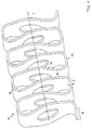
- FIG. 10 shows a band spring 31 according to the invention in an eighth Ausurugsform comprising a spring band with wave-shaped course meandering around a longitudinal center line L and has four complete wave units.
- four complete first reversal regions 12 and three complete and two half-cut second reversal regions 13 can be seen, wherein the half-turn regions define the ends of the band spring 31.
- the more curved return portions 12, 13 are connected by intermediate portions 14, 15 of lesser curvature.
- the material thickness of the spring band is variable, wherein the thickness H of the band spring in the reverse regions 12, 13 is substantially higher than in the connecting regions 14, 15.
- the thickness changes are hereby largely continuous.
- the holes 16 ' are deviating from the previously shown non-circular or elliptical, but lens-shaped, wherein the longitudinal extension occurs in the direction of the longitudinal course of the spring band.
- the material width of the two parts of the intermediate sections 14, 15 is effectively approximately constant in the region of the holes 16 ', bulges of the intermediate sections resulting from the lens shape of the holes 16'.
- the thickness variation of the spring band can be made by placing additional prepregs in the reversal regions 12, 13 which do not extend over the entire length of the corrugated spring band like the base prepregs.
- Both the first reversal regions 12 and the second reversal regions 13 additionally show wrapping sections 17, 18 which are intended to show fiber convolutions which are applied to the reversal regions 12, 13 transversely to the longitudinal course of the spring band before or after the formation of the wave as reinforcing windings. Excluded from the Faserumwicklept are only the half-cut reversal areas at the ends of the band spring.
- the band spring 31 can be seen as a further additional detail a layered structure of the spring band comprising a middle layer 19 with variable thickness profile, for example made of prepregs, and outer layers 32, 33 of fiber composite material of increased quality, for example made of resin-impregnated fiber mats or fiber strands, in particular carbon fiber ,
- the layered construction extends, although in the wrapping areas 17, 18 not recognizable over the entire length of the spring band.
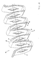
- FIG. 11 is an exploded view in the direction of the longitudinal central axis L, while in FIG. 12 a ready to use assembly is recognizable.
- FIG. 11 and 12 are parts of a damper unit 20 with the strip spring 31 according to the invention after FIG. 10 partially assembled or shown assembled.
- an outer damper tube 22 with a first spring plate 24 and an inner damper tube 23 with a second spring plate 25 are each firmly connected.
- the inner damper tube is inserted through the holes 16 'of the intermediate sections 14, 15, wherein the details of the finished damper unit 20 are not all recognizable.
- the outer damper tube 22 may extend much further beyond the inner damper tube 23 and also be inserted through a portion of the holes 16 '.
- the upper and lower spring plates 24, 25 are curved band sections made of sheet metal, which create a flat against the terminal intermediate sections 14, 15 of the wave train of the band spring, so that recognizable these supported intermediate sections themselves are not subjected to bending. In that regard, the width or thickness variation of the spring band is of little importance in these areas. However, in each case the last complete reversal regions 12, 13, which stand out from the spring plates 24, 25, are already designed according to the invention with an increased bending resistance torque.
- the damper unit 20 is also known to guide the spring band, ie a lateral buckling in the median plane of the wave train or perpendicular to the median plane of the wave train is prevented by the leadership of the holes 16 'on the damper unit 20.
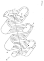
- FIG. 13 a band spring 41 of the second double-shaft type according to the invention is shown, on which two wave trains 51, 52 can be seen, wherein the first wave train 51 meanders around a first center axis L1 and the second wave train 52 meanders about a second center axis L2, which are parallel to each other. Parallel and centrally between the longitudinal center lines L1 and L2 is a RescuelHarsschlinin L, which corresponds approximately to the direction of the force introduction line K.
- the first wave train 51 has outer reverse regions 42 and inner reverse regions 43 which are interconnected by intermediate sections 44, 45 of low bend.
- the second wave train 52 has outer reverse regions 46 and inner reverse regions 47 interconnected by intermediate portions 48, 49 of less flexing.
- the width B of the wave trains changes to a lesser extent than the thickness H of the wave trains 51, 52, which is greatest in the outer return areas 42, 46, while a smaller thickness increase also in the inner return areas 43, 47 in relation to the intermediate sections 46, 47, 48, 49 can be seen.
- the outer reverse regions 42, 46 are reinforced with additional Faserumwicklept 59, 60, which lead to an additional increase of the bending resistance torque. Also in reference to the band feather after the FIGS.
- a layered structure of the wave trains 51, 52 can be seen, wherein in each case a middle layer 53, 54 represents the variable thickness, while outer layers 55, 56, 57, 58 of higher quality material over the length of the band spring have a constant thickness.
- the higher quality material for example, strands or fabric mats from carbon fiber, aramid fibers or metal fibers, while the inner middle layers 53, 54 may be constructed of prepregs of glass fiber mats.
- the two wave trains 51, 52 are connected to each other at the respective inner reverse regions 43, 47. Even if the graphical representation makes it appear that two independent wave trains are initially completed and then connected to each other, it is actually possible that fiber strands of one wave train continue to run in the other wave train in the connecting regions of the wave trains and vice versa.
- the double-wave strip spring shown is thus as to understand a single entity.
- lenticular holes 61 When viewed in the direction of the longitudinal center line L, lenticular holes 61, for example, penetrate the inner reversal areas symmetrically.
- the reverse regions are widened so that their effective width approximates the effective width of the outer reverse regions 42, 43, i. So the effective width is about constant, neglecting the through holes.
- the function of the through holes 61 can be seen from the following figure.
- FIG. 14 are the same details as in FIG. 13 provided with the same reference numerals, wherein only a part of the reference numerals of the essential features is adopted. Reference is made to the preceding description.
- a damper unit 40 is inserted, wherein an outer damper tube 62 is connected to a lower spring plate 64, in which an inner damper tube 63 is inserted, which is designed with an upper spring plate 65.
- the spring plates 64, 65 are curved band body made of sheet metal, which create 51 and 52 flat on the last connecting portions of the wave trains, so that they can be introduced into these forces without themselves being subjected to bending. Bending forces act on the first of the spring plates 64, 65 contrasting outer reverse regions 42, 46, and the entire further spring course.
- the higher loaded outer reverse regions 42, 46 in this case have an increased bending resistance torque, so that the internal stresses in the spring material are aligned with each other, ideally are constant everywhere.
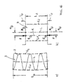
- FIG. 15 a strip spring B according to the invention is shown in side view in schematic representation, which has a straight longitudinal center line L.
- the wave train Z is shown between two parallel boundary lines G 1 , G 2 in a relaxed state with the length L0.
- the shortened band spring B is characterized only by the parallel boundary lines G 1 , G 2 , wherein the band spring is shortened to the length LZ under the action of oppositely directed forces F between two mutually parallel spring plates TO, TU.
- the forces F reach in the direction of a force line of action K, which extends between an upper center of curvature MO and a lower center of curvature MU of the band spring B.
- FIG. 16 a strip spring B according to the invention is shown in side view in a schematic diagram, which has a C-shaped longitudinal center line L.
- the wave train Z is shown between two C-shaped boundary lines G 1 , G 2 in a relaxed state with the length L0.
- the shortened band spring B is characterized only by the now parallel straight boundary lines G 1 , G 2 , wherein the band spring is shortened under the action of oppositely directed forces F between two parallel spring plates TO, TU to the length LZ.
- the forces act in the direction of a force line of action K, which has a rectified equal side offset eo, eu with respect to an upper mean point MO and a lower center of curvature MU of the band spring, so that the force action line K is offset parallel to the longitudinal center line L.
- FIG. 17 a strip spring B according to the invention is shown in a side view in a schematic diagram, which has an S-shaped curved longitudinal center line L.
- the wave train Z is shown between two S-shaped curved boundary lines G 1 , G 2 in a relaxed state with the length L 0,
- the shortened band spring B is characterized only by the now parallel straight boundary lines G 1 , G 2 , wherein the band spring is shortened to the length LZ under the action of two oppositely directed forces F between two mutually parallel spring plates TO, TU.
- the forces act in the direction of the force line of action K, which in relation to an upper binding center MO and a lower binding center MU of the band spring each have an oppositely directed equal side offset eo, eu, so that the force line K intersects the longitudinal center line L at half the length.
- FIG. 18 a strip spring B according to the invention is shown in side view in a schematic diagram, the longitudinal center line L from the superposition of a C-shaped curved Curve and an S-shaped curved curve is formed.
- the wave train Z between two boundary lines G 1 , G 2 is shown in a relaxed state with the length L0, which correspond in their curvature of the longitudinal center line L.
- the shortened band spring is characterized only by the now parallel straight boundary lines G 1 , G 2 , wherein the band spring is shortened to the length LZ under the action of two oppositely directed forces F between two mutually parallel spring plates TO, TU.
- the forces act in the direction of the force line of action K, which extends through an upper center of curvature MO and has a lateral offset eu in relation to a lower binding center MU of the band spring.
Landscapes
- Engineering & Computer Science (AREA)
- General Engineering & Computer Science (AREA)
- Mechanical Engineering (AREA)
- Physics & Mathematics (AREA)
- Acoustics & Sound (AREA)
- Aviation & Aerospace Engineering (AREA)
- Springs (AREA)
Applications Claiming Priority (1)
| Application Number | Priority Date | Filing Date | Title |
|---|---|---|---|
| DE102008006411A DE102008006411A1 (de) | 2008-01-28 | 2008-01-28 | Fahrzeugfeder aus Faserverbundwerkstoff |
Publications (3)
| Publication Number | Publication Date |
|---|---|
| EP2082903A2 true EP2082903A2 (fr) | 2009-07-29 |
| EP2082903A3 EP2082903A3 (fr) | 2009-09-09 |
| EP2082903B1 EP2082903B1 (fr) | 2011-05-11 |
Family
ID=40578318
Family Applications (1)
| Application Number | Title | Priority Date | Filing Date |
|---|---|---|---|
| EP09000685A Not-in-force EP2082903B1 (fr) | 2008-01-28 | 2009-01-20 | Ressort de véhicule en matière active à fibres composites |
Country Status (4)
| Country | Link |
|---|---|
| US (1) | US20090200721A1 (fr) |
| EP (1) | EP2082903B1 (fr) |
| AT (1) | ATE508892T1 (fr) |
| DE (1) | DE102008006411A1 (fr) |
Cited By (9)
| Publication number | Priority date | Publication date | Assignee | Title |
|---|---|---|---|---|
| WO2011128042A1 (fr) | 2010-04-16 | 2011-10-20 | Uwe Hoffmann | Structure à ressorts composée de plusieurs éléments ressort |
| WO2011110611A3 (fr) * | 2010-03-12 | 2011-12-01 | Muhr Und Bender Kg | Ressort à lame pour véhicules automobiles |
| CN102840219A (zh) * | 2012-09-29 | 2012-12-26 | 钟明华 | 一种弹力金属连杆 |
| EP3015310A1 (fr) * | 2014-10-31 | 2016-05-04 | Lisa Dräxlmaier GmbH | Mobilier de véhicule et véhicule |
| US20170015170A1 (en) * | 2014-02-24 | 2017-01-19 | ThyssenKrupp Federn und Stabilisatoren GmbH | Suspension spring unit for a vehicle chassis |
| DE102015012334B3 (de) * | 2015-09-22 | 2017-02-16 | Uwe Hoffmann | Hülsenförmige Federstruktur mit mehreren Bandfedern und Verfahren zur Herstellung einer Bandfeder einer derartigen Federstruktur |
| FR3041400A1 (fr) * | 2015-09-17 | 2017-03-24 | Peugeot Citroen Automobiles Sa | Ressort de suspension de vehicule automobile |
| CN109398015A (zh) * | 2017-12-14 | 2019-03-01 | 刘守银 | 横折板簧总成及独立悬架结构 |
| US20230286134A1 (en) * | 2022-03-10 | 2023-09-14 | John Christian Colley | Flexible Structure, Particularly For Applications In Robotics And Orthopedics |
Families Citing this family (24)
| Publication number | Priority date | Publication date | Assignee | Title |
|---|---|---|---|---|
| DE102008024585B4 (de) | 2008-05-21 | 2017-11-02 | Muhr Und Bender Kg | Federelement für eine Feder-Dämpfer-Anordnung |
| DE102008057463C5 (de) * | 2008-11-14 | 2019-06-13 | Ifc Composite Gmbh | Verfahren und Vorrichtung zur Herstellung einer Feder aus einem Faserverbundwerkstoff |
| DE102008057462B4 (de) * | 2008-11-14 | 2015-04-02 | Ifc Composite Gmbh | Feder aus einem Faserverbundwerkstoff sowie Verfahren und Vorrichtung zur Herstellung derselben |
| DE102009029300A1 (de) * | 2009-09-09 | 2011-04-07 | Leichtbau-Zentrum Sachsen Gmbh | Kunststofffeder für ein Kraftfahrzeugfahrwerk |
| EP2542797B1 (fr) * | 2010-03-01 | 2017-11-22 | Airbus Helicopters | Elément absorbant d'énergie perfectionné et bride de précontrainte associée |
| DE102010061649A1 (de) * | 2010-12-31 | 2012-07-05 | Tobias KELLER | Blattfederelement |
| DE102011075148A1 (de) | 2011-05-03 | 2012-11-08 | Zf Friedrichshafen Ag | Federträger mit einer Tragfeder |
| DE102011080029A1 (de) | 2011-07-28 | 2013-01-31 | Zf Friedrichshafen Ag | Verfahren und Vorrichtung zum Herstellen einer Feder aus Faserverbundwerkstoff |
| US20140315696A1 (en) * | 2011-08-10 | 2014-10-23 | Angelo Gonzalez | Variable rate full body exercise system |
| DE102011081494A1 (de) | 2011-08-24 | 2013-02-28 | Zf Friedrichshafen Ag | Verfahren und Vorrichtung zum Herstellen einer Balgfeder mit quer zur Längsachse der Balgfeder verlaufenden Wellen |
| KR101370109B1 (ko) | 2012-07-23 | 2014-03-06 | 영남대학교 산학협력단 | 지그재그형 스프링 및 이의 제조방법 |
| DE102013223038A1 (de) | 2013-11-12 | 2015-05-13 | Bayerische Motoren Werke Aktiengesellschaft | Anordnung zum Verbinden einer Fahrzeugtragfeder mit einem Fahrzeugaufbau eines Fahrzeugs |
| DE102017129241B4 (de) | 2016-12-09 | 2020-02-13 | Universität Siegen | Federvorrichtung |
| EP3498512B1 (fr) * | 2017-12-12 | 2020-04-08 | C.R.F. Società Consortile per Azioni | Dispositif élastique d'une suspension de moteur de véhicule automobile |
| DE102018206408A1 (de) * | 2018-04-25 | 2019-10-31 | Audi Ag | Federelement |
| DE102018213418B3 (de) | 2018-08-09 | 2019-10-17 | Ford Global Technologies, Llc | Baugruppe für eine Radaufhängung eines Fahrzeugs |
| DE102019109554A1 (de) * | 2019-04-11 | 2020-10-15 | Danto Invention Gmbh & Co. Kg | Biegefederelement aus einem Faserkunststoffverbundmaterial |
| US11781579B1 (en) * | 2019-05-28 | 2023-10-10 | Allfasteners USA, LLC | Blind bolt with collapsible shear sleeve assembly |
| DE102019129581A1 (de) | 2019-11-04 | 2021-05-06 | Danto Invention Gmbh & Co. Kg | Biegefederelement aus einem Faserkunststoffverbundmaterial |
| DE102019218062A1 (de) * | 2019-11-22 | 2021-05-27 | Ford Global Technologies, Llc | Federungsvorrichtung zur Federung eines Fahrgestells eines Kraftfahrzeugs |
| DE102020105157B3 (de) * | 2020-02-27 | 2021-07-01 | Audi Aktiengesellschaft | Radaufhängung für ein Fahrzeug, insbesondere für ein Kraftfahrzeug, sowie Fahrzeug mit einer solchen Radaufhängung |
| KR102186042B1 (ko) * | 2020-04-29 | 2020-12-03 | (주)연우 | 탄성 부재 및 이를 포함하는 펌프 조립체 |
| EP4653144A1 (fr) * | 2024-05-23 | 2025-11-26 | Hilti Aktiengesellschaft | Accumulateur d'énergie composite et outil de travail comprenant un accumulateur d'énergie composite |
| CN119084503B (zh) * | 2024-10-12 | 2026-02-10 | 武汉理工大学 | 基于纤维复合材料周期结构构件阵列的压缩弹簧及其应用 |
Citations (7)
| Publication number | Priority date | Publication date | Assignee | Title |
|---|---|---|---|---|
| US2063216A (en) | 1932-11-30 | 1936-12-08 | Fed Spring Company | Resilient connection |
| EP0132048A1 (fr) | 1983-06-20 | 1985-01-23 | Secretary of State for Trade and Industry in Her Britannic Majesty's Gov. of the U.K. of Great Britain and Northern Ireland | Ressort pour l'accumulation d'une grande quantité d'énergie spécifique |
| EP0245099A1 (fr) | 1986-05-09 | 1987-11-11 | Gkn Technology Limited | Dispositifs de montage pour ressort |
| DE3641108A1 (de) | 1986-12-02 | 1988-06-16 | Josef Gail | Federelement |
| US5013013A (en) | 1986-11-15 | 1991-05-07 | Gkn Technology Limited | Spring assemblies |
| DE19962026A1 (de) | 1999-12-22 | 2001-06-28 | Volkswagen Ag | Feder/Dämpferanordnung für ein Kraftfahrzeug |
| US20070267792A1 (en) | 2005-08-13 | 2007-11-22 | Elmoselhy Salah A M | Sigma-springs for suspension systems |
Family Cites Families (9)
| Publication number | Priority date | Publication date | Assignee | Title |
|---|---|---|---|---|
| US2363785A (en) * | 1943-08-17 | 1944-11-28 | Einson Freeman Co Inc | Motive power for toys and the like |
| US3115337A (en) * | 1961-12-13 | 1963-12-24 | Daniel D Musgrave | Variable spring |
| DE10125503C1 (de) * | 2001-05-23 | 2002-12-12 | Muhr & Bender Kg | Radaufhängung |
| US3737155A (en) * | 1971-06-21 | 1973-06-05 | J Karlan | Combination vibration isolator and shock absorber |
| US4805885A (en) * | 1982-12-21 | 1989-02-21 | Amp Incorporated | Sinuous spring |
| GB8500605D0 (en) * | 1985-01-10 | 1985-02-13 | Secretary Trade Ind Brit | Damped spring |
| GB8517575D0 (en) * | 1985-07-11 | 1985-08-14 | Gkn Technology Ltd | Spring assemblies |
| DE69529450T2 (de) * | 1994-10-14 | 2003-11-20 | Exedy Corp., Neyagawa | Wellenförmige Feder und Dämpfungsmechanismus |
| US20060033252A1 (en) * | 2004-08-13 | 2006-02-16 | Elmoselhy Salah A M | Sigma Sigma-springs for suspension systems |
-
2008
- 2008-01-28 DE DE102008006411A patent/DE102008006411A1/de not_active Ceased
-
2009
- 2009-01-20 EP EP09000685A patent/EP2082903B1/fr not_active Not-in-force
- 2009-01-20 AT AT09000685T patent/ATE508892T1/de active
- 2009-01-28 US US12/321,980 patent/US20090200721A1/en not_active Abandoned
Patent Citations (8)
| Publication number | Priority date | Publication date | Assignee | Title |
|---|---|---|---|---|
| US2063216A (en) | 1932-11-30 | 1936-12-08 | Fed Spring Company | Resilient connection |
| EP0132048A1 (fr) | 1983-06-20 | 1985-01-23 | Secretary of State for Trade and Industry in Her Britannic Majesty's Gov. of the U.K. of Great Britain and Northern Ireland | Ressort pour l'accumulation d'une grande quantité d'énergie spécifique |
| EP0245099A1 (fr) | 1986-05-09 | 1987-11-11 | Gkn Technology Limited | Dispositifs de montage pour ressort |
| US4927124A (en) | 1986-05-09 | 1990-05-22 | Gkn Technology Limited | Spring assemblies |
| US5013013A (en) | 1986-11-15 | 1991-05-07 | Gkn Technology Limited | Spring assemblies |
| DE3641108A1 (de) | 1986-12-02 | 1988-06-16 | Josef Gail | Federelement |
| DE19962026A1 (de) | 1999-12-22 | 2001-06-28 | Volkswagen Ag | Feder/Dämpferanordnung für ein Kraftfahrzeug |
| US20070267792A1 (en) | 2005-08-13 | 2007-11-22 | Elmoselhy Salah A M | Sigma-springs for suspension systems |
Cited By (13)
| Publication number | Priority date | Publication date | Assignee | Title |
|---|---|---|---|---|
| WO2011110611A3 (fr) * | 2010-03-12 | 2011-12-01 | Muhr Und Bender Kg | Ressort à lame pour véhicules automobiles |
| WO2011128042A1 (fr) | 2010-04-16 | 2011-10-20 | Uwe Hoffmann | Structure à ressorts composée de plusieurs éléments ressort |
| DE102010015469A1 (de) | 2010-04-16 | 2011-10-20 | Uwe Hoffmann | Federstruktur aus mehreren Federelementen |
| CN102840219A (zh) * | 2012-09-29 | 2012-12-26 | 钟明华 | 一种弹力金属连杆 |
| US10675935B2 (en) * | 2014-02-24 | 2020-06-09 | ThyssenKrupp Federn und Stabilisatoren GmbH | Suspension spring unit for a vehicle chassis |
| US20170015170A1 (en) * | 2014-02-24 | 2017-01-19 | ThyssenKrupp Federn und Stabilisatoren GmbH | Suspension spring unit for a vehicle chassis |
| EP3015310A1 (fr) * | 2014-10-31 | 2016-05-04 | Lisa Dräxlmaier GmbH | Mobilier de véhicule et véhicule |
| FR3041400A1 (fr) * | 2015-09-17 | 2017-03-24 | Peugeot Citroen Automobiles Sa | Ressort de suspension de vehicule automobile |
| DE102015012334B3 (de) * | 2015-09-22 | 2017-02-16 | Uwe Hoffmann | Hülsenförmige Federstruktur mit mehreren Bandfedern und Verfahren zur Herstellung einer Bandfeder einer derartigen Federstruktur |
| CN109398015A (zh) * | 2017-12-14 | 2019-03-01 | 刘守银 | 横折板簧总成及独立悬架结构 |
| CN109398015B (zh) * | 2017-12-14 | 2021-06-01 | 刘守银 | 横折板簧总成及独立悬架结构 |
| US20230286134A1 (en) * | 2022-03-10 | 2023-09-14 | John Christian Colley | Flexible Structure, Particularly For Applications In Robotics And Orthopedics |
| US11780079B2 (en) * | 2022-03-10 | 2023-10-10 | John Christian Colley | Flexible structure, particularly for applications in robotics and orthopedics |
Also Published As
| Publication number | Publication date |
|---|---|
| EP2082903A3 (fr) | 2009-09-09 |
| US20090200721A1 (en) | 2009-08-13 |
| ATE508892T1 (de) | 2011-05-15 |
| DE102008006411A1 (de) | 2009-07-30 |
| EP2082903B1 (fr) | 2011-05-11 |
Similar Documents
| Publication | Publication Date | Title |
|---|---|---|
| EP2082903B1 (fr) | Ressort de véhicule en matière active à fibres composites | |
| DE69220784T2 (de) | Flexible rohrförmige struktur | |
| EP0055364B2 (fr) | Composant de protection contre une collision | |
| DE102017218553B4 (de) | Herstellungsverfahren für Blattfedern aus faserverstärktem Kunststoff mit integrierten Augenbuchsen und Blattfeder aus faserverstärktem Kunststoff | |
| EP2361752B1 (fr) | Composant en composite de fibre et son procédé de fabrication | |
| DE2622163B2 (de) | Profilträger aus faserverstärktem Werkstoff | |
| DE102008024585B4 (de) | Federelement für eine Feder-Dämpfer-Anordnung | |
| DE102016009640A1 (de) | Gurt aus vorgefertigten Elementen mit Gelege und ein Verfahren zu seiner Fertigung | |
| EP2670581B1 (fr) | Procédé, semi-produit pour la production d'un composant renforcé par des fibres d'une éolienne et utilisation du semi-produit | |
| DE102019109554A1 (de) | Biegefederelement aus einem Faserkunststoffverbundmaterial | |
| WO2018130561A1 (fr) | Profilé extrudé et procédé de fabrication d'un profilé extrudé | |
| EP3723963B1 (fr) | Procédé de fabrication d'un composant et composant | |
| DE102012211765A1 (de) | Kernschicht für ein Sandwichverbundbauteil, Sandwichverbundbauteil und Verfahren zur Herstellung eines Sandwichverbundbauteils | |
| EP0690228B1 (fr) | Manchette de montage et poutre de flexion pour pale aérodynamique | |
| DE102015012334B3 (de) | Hülsenförmige Federstruktur mit mehreren Bandfedern und Verfahren zur Herstellung einer Bandfeder einer derartigen Federstruktur | |
| EP3490782B1 (fr) | Procédé pour la fabrication d'une pièce composite à fibres multicouche, tridimensionnelle | |
| DE10253300A1 (de) | Faserverstärkter Verbundkunststoff zur Herstellung von Strukturbauteilen, Strukturbauteile aus einem derartigen Verbundkunststoff sowie Verfahren zur Herstellung von faserverstärkten Strukturbauteilen | |
| EP3298294B1 (fr) | Dispositif d'accouplement à crabots pourvu d'éléments d'accouplement à structure composite renforcée par des fibres | |
| DE102019206217A1 (de) | Fahrwerklenker | |
| DE102014113294A1 (de) | Maschinenelement und Verfahren zur Herstellung eines Maschinenelements | |
| WO2019020703A1 (fr) | Procédé de fabrication d'un ressort hélicoïdal | |
| EP0261375B1 (fr) | Procédé pour la fabrication d'une poutre creuse en matériau composite renforcé par des fibres | |
| EP3030781B1 (fr) | Élément composite et procédé de fabrication d'un élément composite | |
| DE102013205440A1 (de) | Verfahren zur Herstellung eines Faserverbundbauteils mit verstärktem Anbindungsabschnitt zur lokalen Krafteinleitung | |
| DE3315292A1 (de) | Bremsband fuer transmissionsbremsen |
Legal Events
| Date | Code | Title | Description |
|---|---|---|---|
| PUAI | Public reference made under article 153(3) epc to a published international application that has entered the european phase |
Free format text: ORIGINAL CODE: 0009012 |
|
| AK | Designated contracting states |
Kind code of ref document: A2 Designated state(s): AT BE BG CH CY CZ DE DK EE ES FI FR GB GR HR HU IE IS IT LI LT LU LV MC MK MT NL NO PL PT RO SE SI SK TR |
|
| AX | Request for extension of the european patent |
Extension state: AL BA RS |
|
| PUAL | Search report despatched |
Free format text: ORIGINAL CODE: 0009013 |
|
| AK | Designated contracting states |
Kind code of ref document: A3 Designated state(s): AT BE BG CH CY CZ DE DK EE ES FI FR GB GR HR HU IE IS IT LI LT LU LV MC MK MT NL NO PL PT RO SE SI SK TR |
|
| AX | Request for extension of the european patent |
Extension state: AL BA RS |
|
| 17P | Request for examination filed |
Effective date: 20090916 |
|
| 17Q | First examination report despatched |
Effective date: 20091013 |
|
| AKX | Designation fees paid |
Designated state(s): AT BE BG CH CY CZ DE DK EE ES FI FR GB GR HR HU IE IS IT LI LT LU LV MC MK MT NL NO PL PT RO SE SI SK TR |
|
| RIC1 | Information provided on ipc code assigned before grant |
Ipc: F16F 1/02 20060101ALI20100924BHEP Ipc: B60G 11/00 20060101AFI20100924BHEP Ipc: F16F 1/366 20060101ALI20100924BHEP |
|
| GRAP | Despatch of communication of intention to grant a patent |
Free format text: ORIGINAL CODE: EPIDOSNIGR1 |
|
| GRAC | Information related to communication of intention to grant a patent modified |
Free format text: ORIGINAL CODE: EPIDOSCIGR1 |
|
| GRAS | Grant fee paid |
Free format text: ORIGINAL CODE: EPIDOSNIGR3 |
|
| GRAA | (expected) grant |
Free format text: ORIGINAL CODE: 0009210 |
|
| AK | Designated contracting states |
Kind code of ref document: B1 Designated state(s): AT BE BG CH CY CZ DE DK EE ES FI FR GB GR HR HU IE IS IT LI LT LU LV MC MK MT NL NO PL PT RO SE SI SK TR |
|
| REG | Reference to a national code |
Ref country code: GB Ref legal event code: FG4D Free format text: NOT ENGLISH |
|
| REG | Reference to a national code |
Ref country code: CH Ref legal event code: EP |
|
| REG | Reference to a national code |
Ref country code: IE Ref legal event code: FG4D |
|
| REG | Reference to a national code |
Ref country code: DE Ref legal event code: R096 Ref document number: 502009000635 Country of ref document: DE Effective date: 20110622 |
|
| REG | Reference to a national code |
Ref country code: NL Ref legal event code: VDEP Effective date: 20110511 |
|
| PG25 | Lapsed in a contracting state [announced via postgrant information from national office to epo] |
Ref country code: NO Free format text: LAPSE BECAUSE OF FAILURE TO SUBMIT A TRANSLATION OF THE DESCRIPTION OR TO PAY THE FEE WITHIN THE PRESCRIBED TIME-LIMIT Effective date: 20110811 Ref country code: LT Free format text: LAPSE BECAUSE OF FAILURE TO SUBMIT A TRANSLATION OF THE DESCRIPTION OR TO PAY THE FEE WITHIN THE PRESCRIBED TIME-LIMIT Effective date: 20110511 Ref country code: SE Free format text: LAPSE BECAUSE OF FAILURE TO SUBMIT A TRANSLATION OF THE DESCRIPTION OR TO PAY THE FEE WITHIN THE PRESCRIBED TIME-LIMIT Effective date: 20110511 Ref country code: PT Free format text: LAPSE BECAUSE OF FAILURE TO SUBMIT A TRANSLATION OF THE DESCRIPTION OR TO PAY THE FEE WITHIN THE PRESCRIBED TIME-LIMIT Effective date: 20110912 |
|
| PG25 | Lapsed in a contracting state [announced via postgrant information from national office to epo] |
Ref country code: IS Free format text: LAPSE BECAUSE OF FAILURE TO SUBMIT A TRANSLATION OF THE DESCRIPTION OR TO PAY THE FEE WITHIN THE PRESCRIBED TIME-LIMIT Effective date: 20110911 Ref country code: SI Free format text: LAPSE BECAUSE OF FAILURE TO SUBMIT A TRANSLATION OF THE DESCRIPTION OR TO PAY THE FEE WITHIN THE PRESCRIBED TIME-LIMIT Effective date: 20110511 Ref country code: LV Free format text: LAPSE BECAUSE OF FAILURE TO SUBMIT A TRANSLATION OF THE DESCRIPTION OR TO PAY THE FEE WITHIN THE PRESCRIBED TIME-LIMIT Effective date: 20110511 Ref country code: GR Free format text: LAPSE BECAUSE OF FAILURE TO SUBMIT A TRANSLATION OF THE DESCRIPTION OR TO PAY THE FEE WITHIN THE PRESCRIBED TIME-LIMIT Effective date: 20110812 Ref country code: CY Free format text: LAPSE BECAUSE OF FAILURE TO SUBMIT A TRANSLATION OF THE DESCRIPTION OR TO PAY THE FEE WITHIN THE PRESCRIBED TIME-LIMIT Effective date: 20110511 Ref country code: FI Free format text: LAPSE BECAUSE OF FAILURE TO SUBMIT A TRANSLATION OF THE DESCRIPTION OR TO PAY THE FEE WITHIN THE PRESCRIBED TIME-LIMIT Effective date: 20110511 Ref country code: ES Free format text: LAPSE BECAUSE OF FAILURE TO SUBMIT A TRANSLATION OF THE DESCRIPTION OR TO PAY THE FEE WITHIN THE PRESCRIBED TIME-LIMIT Effective date: 20110822 |
|
| REG | Reference to a national code |
Ref country code: IE Ref legal event code: FD4D |
|
| PG25 | Lapsed in a contracting state [announced via postgrant information from national office to epo] |
Ref country code: NL Free format text: LAPSE BECAUSE OF FAILURE TO SUBMIT A TRANSLATION OF THE DESCRIPTION OR TO PAY THE FEE WITHIN THE PRESCRIBED TIME-LIMIT Effective date: 20110511 |
|
| PG25 | Lapsed in a contracting state [announced via postgrant information from national office to epo] |
Ref country code: CZ Free format text: LAPSE BECAUSE OF FAILURE TO SUBMIT A TRANSLATION OF THE DESCRIPTION OR TO PAY THE FEE WITHIN THE PRESCRIBED TIME-LIMIT Effective date: 20110511 Ref country code: EE Free format text: LAPSE BECAUSE OF FAILURE TO SUBMIT A TRANSLATION OF THE DESCRIPTION OR TO PAY THE FEE WITHIN THE PRESCRIBED TIME-LIMIT Effective date: 20110511 Ref country code: IE Free format text: LAPSE BECAUSE OF FAILURE TO SUBMIT A TRANSLATION OF THE DESCRIPTION OR TO PAY THE FEE WITHIN THE PRESCRIBED TIME-LIMIT Effective date: 20110511 |
|
| PG25 | Lapsed in a contracting state [announced via postgrant information from national office to epo] |
Ref country code: DK Free format text: LAPSE BECAUSE OF FAILURE TO SUBMIT A TRANSLATION OF THE DESCRIPTION OR TO PAY THE FEE WITHIN THE PRESCRIBED TIME-LIMIT Effective date: 20110511 Ref country code: PL Free format text: LAPSE BECAUSE OF FAILURE TO SUBMIT A TRANSLATION OF THE DESCRIPTION OR TO PAY THE FEE WITHIN THE PRESCRIBED TIME-LIMIT Effective date: 20110511 Ref country code: RO Free format text: LAPSE BECAUSE OF FAILURE TO SUBMIT A TRANSLATION OF THE DESCRIPTION OR TO PAY THE FEE WITHIN THE PRESCRIBED TIME-LIMIT Effective date: 20110511 Ref country code: SK Free format text: LAPSE BECAUSE OF FAILURE TO SUBMIT A TRANSLATION OF THE DESCRIPTION OR TO PAY THE FEE WITHIN THE PRESCRIBED TIME-LIMIT Effective date: 20110511 |
|
| PLBE | No opposition filed within time limit |
Free format text: ORIGINAL CODE: 0009261 |
|
| STAA | Information on the status of an ep patent application or granted ep patent |
Free format text: STATUS: NO OPPOSITION FILED WITHIN TIME LIMIT |
|
| 26N | No opposition filed |
Effective date: 20120214 |
|
| PG25 | Lapsed in a contracting state [announced via postgrant information from national office to epo] |
Ref country code: HR Free format text: LAPSE BECAUSE OF FAILURE TO SUBMIT A TRANSLATION OF THE DESCRIPTION OR TO PAY THE FEE WITHIN THE PRESCRIBED TIME-LIMIT Effective date: 20111123 Ref country code: IT Free format text: LAPSE BECAUSE OF FAILURE TO SUBMIT A TRANSLATION OF THE DESCRIPTION OR TO PAY THE FEE WITHIN THE PRESCRIBED TIME-LIMIT Effective date: 20110511 |
|
| REG | Reference to a national code |
Ref country code: DE Ref legal event code: R097 Ref document number: 502009000635 Country of ref document: DE Effective date: 20120214 |
|
| BERE | Be: lapsed |
Owner name: MUHR UND BENDER K.G. Effective date: 20120131 |
|
| PG25 | Lapsed in a contracting state [announced via postgrant information from national office to epo] |
Ref country code: MC Free format text: LAPSE BECAUSE OF NON-PAYMENT OF DUE FEES Effective date: 20120131 |
|
| PG25 | Lapsed in a contracting state [announced via postgrant information from national office to epo] |
Ref country code: BE Free format text: LAPSE BECAUSE OF NON-PAYMENT OF DUE FEES Effective date: 20120131 |
|
| PG25 | Lapsed in a contracting state [announced via postgrant information from national office to epo] |
Ref country code: MK Free format text: LAPSE BECAUSE OF FAILURE TO SUBMIT A TRANSLATION OF THE DESCRIPTION OR TO PAY THE FEE WITHIN THE PRESCRIBED TIME-LIMIT Effective date: 20110511 |
|
| PG25 | Lapsed in a contracting state [announced via postgrant information from national office to epo] |
Ref country code: BG Free format text: LAPSE BECAUSE OF FAILURE TO SUBMIT A TRANSLATION OF THE DESCRIPTION OR TO PAY THE FEE WITHIN THE PRESCRIBED TIME-LIMIT Effective date: 20110811 |
|
| PG25 | Lapsed in a contracting state [announced via postgrant information from national office to epo] |
Ref country code: MT Free format text: LAPSE BECAUSE OF FAILURE TO SUBMIT A TRANSLATION OF THE DESCRIPTION OR TO PAY THE FEE WITHIN THE PRESCRIBED TIME-LIMIT Effective date: 20110511 |
|
| REG | Reference to a national code |
Ref country code: CH Ref legal event code: PL |
|
| GBPC | Gb: european patent ceased through non-payment of renewal fee |
Effective date: 20130120 |
|
| PG25 | Lapsed in a contracting state [announced via postgrant information from national office to epo] |
Ref country code: LI Free format text: LAPSE BECAUSE OF NON-PAYMENT OF DUE FEES Effective date: 20130131 Ref country code: CH Free format text: LAPSE BECAUSE OF NON-PAYMENT OF DUE FEES Effective date: 20130131 |
|
| PG25 | Lapsed in a contracting state [announced via postgrant information from national office to epo] |
Ref country code: GB Free format text: LAPSE BECAUSE OF NON-PAYMENT OF DUE FEES Effective date: 20130120 Ref country code: HR Free format text: LAPSE BECAUSE OF FAILURE TO SUBMIT A TRANSLATION OF THE DESCRIPTION OR TO PAY THE FEE WITHIN THE PRESCRIBED TIME-LIMIT Effective date: 20110511 |
|
| PG25 | Lapsed in a contracting state [announced via postgrant information from national office to epo] |
Ref country code: TR Free format text: LAPSE BECAUSE OF FAILURE TO SUBMIT A TRANSLATION OF THE DESCRIPTION OR TO PAY THE FEE WITHIN THE PRESCRIBED TIME-LIMIT Effective date: 20110511 |
|
| PG25 | Lapsed in a contracting state [announced via postgrant information from national office to epo] |
Ref country code: LU Free format text: LAPSE BECAUSE OF NON-PAYMENT OF DUE FEES Effective date: 20120120 |
|
| PG25 | Lapsed in a contracting state [announced via postgrant information from national office to epo] |
Ref country code: HU Free format text: LAPSE BECAUSE OF FAILURE TO SUBMIT A TRANSLATION OF THE DESCRIPTION OR TO PAY THE FEE WITHIN THE PRESCRIBED TIME-LIMIT Effective date: 20090120 |
|
| REG | Reference to a national code |
Ref country code: AT Ref legal event code: MM01 Ref document number: 508892 Country of ref document: AT Kind code of ref document: T Effective date: 20140120 |
|
| PG25 | Lapsed in a contracting state [announced via postgrant information from national office to epo] |
Ref country code: AT Free format text: LAPSE BECAUSE OF NON-PAYMENT OF DUE FEES Effective date: 20140120 |
|
| REG | Reference to a national code |
Ref country code: FR Ref legal event code: PLFP Year of fee payment: 8 |
|
| REG | Reference to a national code |
Ref country code: FR Ref legal event code: PLFP Year of fee payment: 9 |
|
| REG | Reference to a national code |
Ref country code: FR Ref legal event code: PLFP Year of fee payment: 10 |
|
| PGFP | Annual fee paid to national office [announced via postgrant information from national office to epo] |
Ref country code: FR Payment date: 20181228 Year of fee payment: 11 |
|
| PGFP | Annual fee paid to national office [announced via postgrant information from national office to epo] |
Ref country code: DE Payment date: 20190103 Year of fee payment: 11 |
|
| REG | Reference to a national code |
Ref country code: DE Ref legal event code: R119 Ref document number: 502009000635 Country of ref document: DE |
|
| PG25 | Lapsed in a contracting state [announced via postgrant information from national office to epo] |
Ref country code: FR Free format text: LAPSE BECAUSE OF NON-PAYMENT OF DUE FEES Effective date: 20200131 Ref country code: DE Free format text: LAPSE BECAUSE OF NON-PAYMENT OF DUE FEES Effective date: 20200801 |