EP2082923B1 - Anordnung zur Montage einer Zierkappe im Innern eines Scheinwerfergehäuses, die mit Befestigungsmitteln für die Zierkappe auf einem Verschlussglas des Gehäuses ausgestattet ist - Google Patents
Anordnung zur Montage einer Zierkappe im Innern eines Scheinwerfergehäuses, die mit Befestigungsmitteln für die Zierkappe auf einem Verschlussglas des Gehäuses ausgestattet ist Download PDFInfo
- Publication number
- EP2082923B1 EP2082923B1 EP09151096A EP09151096A EP2082923B1 EP 2082923 B1 EP2082923 B1 EP 2082923B1 EP 09151096 A EP09151096 A EP 09151096A EP 09151096 A EP09151096 A EP 09151096A EP 2082923 B1 EP2082923 B1 EP 2082923B1
- Authority
- EP
- European Patent Office
- Prior art keywords
- glass
- securing
- lug
- arrangement according
- housing
- Prior art date
- Legal status (The legal status is an assumption and is not a legal conclusion. Google has not performed a legal analysis and makes no representation as to the accuracy of the status listed.)
- Active
Links
Images


Classifications
-
- B—PERFORMING OPERATIONS; TRANSPORTING
- B60—VEHICLES IN GENERAL
- B60R—VEHICLES, VEHICLE FITTINGS, OR VEHICLE PARTS, NOT OTHERWISE PROVIDED FOR
- B60R13/00—Elements for body-finishing, identifying, or decorating; Arrangements or adaptations for advertising purposes
-
- F—MECHANICAL ENGINEERING; LIGHTING; HEATING; WEAPONS; BLASTING
- F21—LIGHTING
- F21S—NON-PORTABLE LIGHTING DEVICES; SYSTEMS THEREOF; VEHICLE LIGHTING DEVICES SPECIALLY ADAPTED FOR VEHICLE EXTERIORS
- F21S41/00—Illuminating devices specially adapted for vehicle exteriors, e.g. headlamps
- F21S41/50—Illuminating devices specially adapted for vehicle exteriors, e.g. headlamps characterised by aesthetic components not otherwise provided for, e.g. decorative trim, partition walls or covers
- F21S41/55—Attachment thereof
-
- F—MECHANICAL ENGINEERING; LIGHTING; HEATING; WEAPONS; BLASTING
- F21—LIGHTING
- F21S—NON-PORTABLE LIGHTING DEVICES; SYSTEMS THEREOF; VEHICLE LIGHTING DEVICES SPECIALLY ADAPTED FOR VEHICLE EXTERIORS
- F21S41/00—Illuminating devices specially adapted for vehicle exteriors, e.g. headlamps
- F21S41/20—Illuminating devices specially adapted for vehicle exteriors, e.g. headlamps characterised by refractors, transparent cover plates, light guides or filters
- F21S41/29—Attachment thereof
Definitions
- the invention relates to an arrangement for mounting a hubcap inside a motor vehicle headlight box.
- This game is accentuated in certain types of motor vehicle headlamps comprising a mobile optical module, for example the projectors equipped with Xenon lamps, provided with means for rotating the light beams they emit: vertical orientation of the light beams according to the attitude of the vehicle or horizontal orientation according to the angular position of the steering wheel.
- the pivoting of the light beam is obtained by pivoting at least one reflector of the projector.
- the hubcap is attached to the housing by means of brackets which are inserted into a fixing groove which extends around the periphery of the front opening of the housing. In this same attachment groove, a peripheral rim of the ice is received to seal the closure glass.
- the fastening lugs of the hubcap are positioned against an inner face of the rim of the ice in an assembled position, without the hubcap being attached to the ice. Then, a bead of glue having previously been deposited at the bottom of the fixing groove, the ice flange and the fastening lugs are then inserted simultaneously rearwardly in a direction of mounting usually longitudinal in the fastening groove of the housing to a mounted position in which they crush the bead of glue.
- the hubcap and the ice must be held in this mounted position until their adhesion with the bead of glue is sufficient for their attachment, that is to say until the hubcap and the ice are fixed together by gluing to the housing by glue, once the polymerized glue.
- the hubcap is positioned on the ice in the assembled position prior to their mounting in the housing fixing groove.
- the two parts slide relative to each other between the moment of their mutual positioning and their mounting on the housing, because the glue is not yet polymerized. This forces positioning corrections just before the mounting operation which are time consuming.
- the hubcap being housed inside the housing during the bonding operation, it is not possible to maintain it individually or to correct the position because the ice prevents access to the inside of the housing. casing through the opening.
- the invention proposes an arrangement of the type described above, characterized in that it comprises means for fixing, prior to their mounting on the housing, the ice trim in its position assembled by the intermediate of its bracket.
- the fastening means comprise at least one vertical abutment face which is arranged at the front end of the slides and against which one face of the fastening tab is capable of coming into abutment for limit the longitudinal displacement towards the front of the bracket in its assembled position.
- said vertical abutment face is formed by the rear end vertical face of a parallelepipedal projection interposed between the slides and the closing portion of the ice, the front end of said fixing lug being capable of to abut with the rear end vertical face of said parallelepipedal projection.
- the slides comprise a groove and a wall closing this groove towards the front, this wall constituting said vertical abutment face, the fixing lug comprising tongues extending transversely, the leading end edges of said tongues being capable of abutting against said vertical abutment face.
- the terms "front” and “rear” in this paragraph are defined in relation to the direction of attachment of the bracket to the ice, that is to say towards the face of the window that closes the housing of the projector.
- the fixing means are preferably made integrally in one piece with the ice.
- the present invention also relates to a motor vehicle headlamp comprising an arrangement according to the present invention.
- inner and outer respectively are used to designate faces which extend longitudinally and which are respectively oriented towards the inside and the outside of the projector casing.
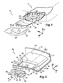
- figure 1 a light projector 10 of a motor vehicle 12. This is a front left projector.
- the projector 10 comprises a housing 14 which has a front opening 16.
- a transparent front closure glass 18 is mounted on the housing 14 so as to seal the front opening 16.
- the casing 14 thus sealed is intended to enclose one or more optical modules (not shown) which are capable of emitting a light beam.
- the housing 14 is for example made of a plastic material.
- the periphery of the front opening 16 of the housing 14 has a fixing groove 20 which is open longitudinally forwards.
- the groove 20 thus has a closed contour which surrounds the front opening 16.
- the ice 18 has a generally curved central closure portion 21 that is generally vertical, and a peripheral retaining flange 22 extending longitudinally rearwardly to a free rear edge 23 at an angle with the closing portion 21, as shown to the figure 3 .
- the peripheral flange 22 has a shape complementary to that of the groove 20 so that its free rear end is received in the groove 20 to a position mounted in a longitudinal direction of rearward mounting as indicated by the arrow "M" of the figure 1 .
- an adhesive bead 24 is applied in the rear bottom of the groove 20 so that the free rear end edge 23 of the peripheral rim 22 of the ice-cream 18 in the mounted position crushes the adhesive bead 24.
- the bead of glue 24 thus ensures at the same time the attachment of the window 18 to the housing 14 and the sealing of the projector 10.
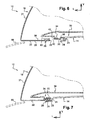
- a protruding rib 26 perpendicularly is arranged on an outer face 28 of the peripheral flange 22 so as to abut against an outer lip 29 of the groove 20 to stop the ice 18 in its mounted position as shown in FIGS. figures 4 and 7 that is, before the free rear end edge 23 of the peripheral flange 22 touches the bottom of the groove 20.
- the projector 10 also comprises a trim 30 which is intended to be housed inside the housing 14 so as to mask some apparent walls of the housing 14, here the bottom wall and the side walls.
- the hubcap 30 thus gives the projector 10 once mounted an aesthetic appearance.
- the front end edge 32 of the trim 30 substantially matches the shape of a lower portion of the contour of the closing portion 21 of the glass 18, shifted inwardly of the housing 14 relative to at the peripheral edge 22 of the ice 18.
- the hubcap 30 is intended to be fixed to the housing 14 of the projector 10, here by three fixing points.
- the trim 30 comprises three longitudinal fastening tabs 34 each comprising a free rear end edge 36 which is intended to be received in the groove 20 of the casing 14 in a position mounted for fastening the trim 30 on the casing 14.
- the trim 30 is intended to be fixed to the casing 14 by bonding its fixing lugs 34 in the groove 20 via said bead of glue 24.
- fastening tabs 34 having a similar structure, a single fastening tab 34 will be described later.
- the bracket 34 is intended to be pressed against an inner face 38 of the peripheral rim 22 of the window 18 in an assembled position.
- the fixing lug 34 is thus in the form of a flat plate parallel to the inner face 38 opposite the peripheral rim 22 of the glass 18.
- the fastening tab 34 extends generally in a horizontal plane.
- the bracket 34 is connected by its leading end edge 40 to the front end edge 32 of the hubcap 30 via a link tab 42 extending generally vertically in a transverse plane. The junction between the fixing lug 34 and the connecting lug 42 thus forms a bend 44.
- the fixing lugs 34 are here all arranged under the underside of the hubcap 30.
- the hubcap 30 is made of a plastic material, for example by molding.
- each fastening tab 34 of the trim 30 is positioned in an assembled position on the glass 18 so as to be pressed against the inner face 38 of the peripheral rim 22 of the glass 18.
- the fastening tabs 34 and the peripheral rim 22 of the glass 18 are simultaneously received rearwardly in the longitudinal mounting direction "M" in the groove 20 of the casing 14 by penetrating the adhesive bead 24 to their position mounted in which the rib 26 is in abutment on the outer lip 29 of the groove 20.
- the free rear end of the fastening tabs 34 is arranged flush with the free rear end edge 23 of the peripheral flange 22 of the ice 18.
- the hubcap 30 and the ice 18 are held in this mounted position until they are glued to the casing 14.
- the trim 30 and the ice 18 are thus fixed jointly and simultaneously to the casing 14 by gluing in the fixing groove 20.
- the hubcap 30 is attached to the ice 18 in the assembled position by at least one of its fastening tabs 34 prior to their simultaneous assembly on the casing 14.
- the glass 18 and the hubcap 30 are integral together and fixed together. relative to each other so as to form a single compact block which is easy to maintain in mounted position in the groove 20 for fixing the housing 14 to the polymerization of the glue of the adhesive bead 24.
- the fixing lug 34 of the trim 30 is preferably fixed by elastic interlocking in fastening means 46 of complementary shape to the peripheral rim 22 of the glass 18.
- ice 18 will be considered as a fixed reference point.
- the three fastening tabs 34 are fixed to the glass 18 by associated fixing means 46 of the glass 18.
- the fixing means 46 being identical, only one of these means 46 will be described later.
- the fastening means 46 of complementary shape of the glass 18 comprise two longitudinally parallel longitudinal slides 48 which are arranged on the inner face 38 of the peripheral flange 22 vis-à-vis the associated fastening tab 34.
- the fastening lug 34 of the trim 30 is thus resiliently engaged in the fastening means 46 of complementary shape in a direction opposite to the longitudinal mounting direction "M", which will be referred to hereinafter as longitudinal interlocking direction. AT".
- the fastening tab 34 is received between the slides 48 so that the fastening tab 34 is immobilized perpendicularly to the longitudinal interlocking direction "A" in all directions.
- each slide 48 has an "L" section.
- a longitudinal core 50 of the slide 48 extends perpendicularly upwards from the inner face 38 of the peripheral rim 22 of the ice 18, and a longitudinal flange 52 extends perpendicularly to the core 50 from its upper end edge. in the direction of the other slide 48.
- a longitudinal groove 54 open towards the other slide 48 is thus delimited vertically by the inner face 38 of the peripheral rim 22 and by the wing 52.
- the slides 48 extend longitudinally towards the closing portion 21 of the ice 18 from the free rear end edge 23 of the peripheral rim 22.
- the slides 48 are here interrupted before reaching the closing portion 21 of the ice 18 .
- each fastening tab 34 form tabs 56 which extend transversely projecting relative to the elbow 44 of junction with the connecting tab 42 associated.
- the tongues 56 are thus intended to be received in each slide 48 vertically between the wing 52 and the inner face 38 of the peripheral flange 22.
- each wing 52 is sufficiently spaced transversely from each other so as to allow the passage of the connecting lug 42 associated with the fixing lug 34.
- the fixing lug 34 is thus received between the webs 50 of the slides 48 with sufficient clearance to allow sliding, but without one of the tabs 56 of the bracket 34 can be removed vertically when the other tongue 56 is transversely in abutment against the core 50 of the associated slide 48.
- each slide 48 has a notch 58 so as to facilitate the insertion of the bracket 34 between the slides 48 by pressing the front end of the bracket 34 vertically against the face internal 38 of the peripheral rim 22 between the two webs 50 before engaging the tongues 56 in the grooves 54 in the longitudinal direction of interlocking "A".
- the fixing means 46 also comprise a rear abutment face 60 to stop the longitudinal sliding towards the front of the fixing lug 34 with respect to the ice 18 in the assembled position in which the free rear end edge the fixing lug 34 is flush with the free rear end edge 23 of the peripheral rim 22 of the window 18.
- the abutment face 60 is here formed by the rear end vertical face of a parallelepipedal projection 62 which is interposed longitudinally between the slides 48 and the closing portion 21 of the ice 18.
- the parallelepipedal projection 62 is formed by a concavity in the outer face 28 of the peripheral rim 22.
- the walls of the parallelepipedal projection 62 are of the same thickness as the rest of the peripheral rim 22 so that its convex imprint rises vertically on the face
- the parallelepipedic projection 62 thus has a rear vertical face and a horizontal upper face and two lateral vertical faces which extend all three longitudinally forwards from the rear face to the portion closing 21 of the ice 18.
- the lower edge of the closing portion 21 of the crystal 18 thus has a recess 64 at the location of the parallelepipedal projection 62. As shown in FIG. figure 4 , this recess 64 is advantageously concealed behind a bodywork element 66 when the headlamp 10 is mounted on the motor vehicle 12.
- the front face of the connecting lug 42 preferably comprises at least one boss 68 which is intended to come into contact with the rear abutment face 60 of the parallelepipedal projection 62 to limit the longitudinal sliding of the fixing lug 34 towards the before.
- the fixing means 46 further comprise a locking pin 70 which extends vertically projecting from the inner face 38 of the peripheral rim 22 of the crystal 18 and which is arranged between the two slides 48.
- the locking pin 70 has a bevelled rear face forming an inclined ramp 72 while its front face is perpendicular to the inner face 38 of the peripheral rim 22.
- the fixing lug 34 has a central through hole forming a notch 74 in which the locking lug 70 of the inner face 38 of the peripheral rim of the glass 18 is intended to be fitted by elastic deformation of the fastening lug 34 to prevent the longitudinal withdrawal towards the rear of the fastening lug 34 when the fastening lug 34 is in the assembled position on the glass 18.
- the notch is more particularly arranged transversely at mid-distance between the lateral tabs 56 of the fastening lug 34 .
- the notch 74 is formed by a notch opening longitudinally in the free rear end edge 36 of the fixing lug 34.
- the notch is formed by a recess which is formed in the lower face of the bracket and which does not open vertically in the upper face of the bracket.
- the ramp 72 inclined locking pin 70 automatically deforms the bracket 34 during movement of the bracket 34 to its assembled position in the longitudinal direction of interlocking "A".
- the fixing means 46 are made integrally with the ice 18, for example by molding a transparent plastic material.
- the fixing lugs 34 are also made integral with the hubcap, for example by molding plastic material.
- the fixing lug 34 is arranged vertically towards the rear in relation to the slides 48 as shown in FIG. figure 3 . Then the fastening tab 34 is moved forwardly in the longitudinal interlocking direction "A" so that the lateral tabs 56 are received in the grooves 54 of the slides 48.
- the fixing lug 34 When the notch 74 of the fixing lug 34 comes into coincidence with the locking lug 70, the fixing lug 34 is resiliently biased towards its resting state and the locking lug 70 penetrates into the notch 74.
- the compact and integral block formed by the trim 30 and the ice 18 is then arranged in the mounted position on the housing 14 so as to be fixed by means of the adhesive bead 24.
- the hubcap 30 being attached to the ice 18 , it is possible to maintain the hubcap 30 in its mounted position relative to the casing 14 acting only on the ice 18 without risk that the hubcap 30 moves relative to the ice 18.
- the mounting operation is thus more accurate and the positioning defects of the trim 30 and the ice 18 on the housing 14 are thus less frequent.
- the positioning of the trim 30 on the ice 18 in the assembled position must be performed only once without risk of movement of the one relative to the other before mounting on the housing 14.
- a second embodiment of the invention has been shown to Figures 5 to 7 .
- the bracket 34 has a similar structure and functions identical to those described in the first embodiment.
- the slides 48 have an identical structure and functions identical to those described in the first embodiment.
- Each slide 48 has in fact an associated rear abutment face 60 which closes the groove 54 longitudinally forwards.
- the abutment rear face 60 is formed by a wall which extends vertically protruding from the inner face 38 of the peripheral rim 22.
- the closing portion 21 of the ice 18 does not have a recess as is the case in the previous embodiment.
- the forward sliding of the fixing lug 34 is stopped by contact between the front end edges of the tongues 56 with the rear abutment face 60. If necessary, as is the case here, the tongues 56 are cut short. relative to the length of the fastening tab 34 so as to have a front shoulder 76 so that the fastening tab 34 is in its assembled position when the shoulders 76 abut against the rear abutment face 60 of the grooves 54.
- tongues 56 is shortened facilitates their insertion into the grooves 54 by vertically pressing the fixing lug portion 34 located in front of the shoulders 76 against the inner face 38 of the peripheral rim 22 between the two webs 50. It is thus not necessary to make notches at the rear end of the wings 52 as is the case in the first embodiment.
- this embodiment is particularly suitable when the peripheral rim 22 of the glass 18 is intended to be arranged flush with the edge of a bodywork element 66 of the motor vehicle 12 as is represented at figure 7 .
- the ice 18 of the first embodiment is easier to manufacture by molding than that of the second embodiment. Indeed, the ice being demolded along a longitudinal axis, the mold will require a drawer (or movement in the mold) for the molding of the slides.
- the locking lug is carried by the underside of the fixing lug while the complementary lug is formed in the inner face of the peripheral flange. ice.
- the locking lug may be arranged either transversely, projecting from a tab of the bracket and being intended to be received , by elastic deformation of the tongue, in a notch of the soul of the associated slide, either vertically protruding on a tongue of the fixing lug and being intended to be received, by elastic deformation of the tongue, in a notch of the wing of the associated slide.
- the arrangement according to the invention thus facilitates the mounting of the trim 30 on the housing 14 while maintaining an invisible fastening between the housing 14, the ice 18 and the trim 30.
Landscapes
- Engineering & Computer Science (AREA)
- General Engineering & Computer Science (AREA)
- Mechanical Engineering (AREA)
- Lighting Device Outwards From Vehicle And Optical Signal (AREA)
- Casings For Electric Apparatus (AREA)
- Projection Apparatus (AREA)
Claims (12)
- Anordnung zur Montage einer Zierkappe (30) innen in einem Gehäuse (14) eines Scheinwerfers (10) eines Kraftfahrzeugs (12) mit:- einer vorderen Scheibe (18) zum Verschließen einer vorderen Öffnung (16) des Gehäuses (14), wobei die Scheibe (18) einen Umfangsrand (22) aufweist, der dazu bestimmt ist, in einer Montagerichtung (M) in einer Nut (20) zur Befestigung der Umrandung der Öffnung (16) des Gehäuses (14) aufgenommen zu werden;- einer Zierkappe (30), die dazu bestimmt ist, innen im Gehäuse (14) gelagert zu werden, und die wenigstens eine Befestigungslasche (34) und Mittel (46) zum Befestigen der Zierkappe (30) mit Hilfe ihrer Befestigungslasche (34) an der Scheibe (18) in montierter Stellung aufweist, bevor diese am Gehäuse (14) angebracht werden,dadurch gekennzeichnet, dass die Befestigungslasche dazu bestimmt ist, in der Montagerichtung (M) in der Befestigungsnut (20) des Gehäuses (14) so aufgenommen zu werden, dass sie mit der Scheibe (18) in einer montierten Stellung gegen eine Innenseite (38) des Umfangsrands (22) der Scheibe (18) gedrückt wird.
- Anordnung nach dem vorhergehenden Anspruch ,
dadurch gekennzeichnet, dass die Befestigungslasche (34) der Zierkappe (30) an der Scheibe (18) durch elastisches Einstecken in einer Einsteckrichtung (A) in komplementär geformte, durch den Umfangsrand (22) der Scheibe (18) gehaltene Befestigungsmittel (46) befestigt ist. - Anordnung nach dem vorhergehenden Anspruch ,
dadurch gekennzeichnet, dass die Einsteckrichtung (A) parallel zur Montagerichtung (M) ist. - Anordnung nach dem vorhergehenden Anspruch,
dadurch gekennzeichnet, dass die komplementär geformten Befestigungsmittel (46) der Scheibe (18) zwei Gleitführungen (48) aufweisen, in denen die Befestigungslasche (34) in montierter Stellung aufgenommen ist und die die Befestigungslasche (34) senkrecht zur Einsteckrichtung (A) in allen Richtungen festhalten. - Anordnung nach dem vorhergehenden Anspruch,
dadurch gekennzeichnet, dass jede Gleitführung (48) einen L-förmigen Querschnitt aufweist, wobei sich ein Steg (50) der Gleitführung (48) senkrecht von der Innenseite (38) des Umfangsrands (22) der Scheibe (18) aus erstreckt, und wobei sich ein Flügel (52) senkrecht zu dem Steg (50) in Richtung auf die andere Gleitführung (48) erstreckt. - Anordnung nach einem der Ansprüche 4 oder 5,
dadurch gekennzeichnet, dass die Befestigungsmittel (46) eine Rastnase (70) aufweisen, die von der Innenseite (38) des Umfangsrands der Scheibe vorsteht und die zwischen den beiden Gleitführungen (48) so angeordnet ist, dass sie beim Einstecken durch elastische Verformung der Befestigungslasche in einem Ausschnitt (74) der Innenseite der Befestigungslasche (34) aufgenommen wird, um das Herausziehen der Befestigungslasche (34) nach einem Einstecken in ihre montierte Stellung zu verhindern. - Anordnung nach dem vorhergehenden Anspruch,
dadurch gekennzeichnet, dass die Rastnase (70) eine Schräge (72) aufweist, die so geneigt ist, dass die Befestigungslasche (34) beim Einstecken automatisch verformt wird. - Anordnung nach einem der Ansprüche 4 bis 7,
dadurch gekennzeichnet, dass die Befestigungsmittel (46) wenigstens eine senkrechte Anschlagfläche (60) aufweisen, die am vorderen Ende der Gleitführungen (48) angeordnet ist und gegen die eine Seite (68) der Befestigungslasche (34) in Anschlag gebracht zu werden vermag, um die Längsverschiebung der Befestigungslasche (34) nach vorne in ihrer montierten Stellung zu begrenzen. - Anordnung nach Anspruch 8,
dadurch gekennzeichnet, dass die senkrechte Anschlagfläche (60) durch die äußere senkrechte Rückseite eines parallelepipedischen Vorsprungs (62) gebildet ist, der zwischen die Gleitführungen (48) und das Abdeckteil (21) der Scheibe (18) eingefügt ist, wobei das vordere Ende der Befestigungslasche (34) mit der äußeren senkrechten Rückseite des parallelepipedischen Vorsprungs (62) in Anschlag gebracht zu werden vermag. - Anordnung nach Anspruch 8,
dadurch gekennzeichnet, dass die Gleitführungen (48) eine Einkerbung (54) und eine die Einkerbung (54) nach vorne verschließende Wand aufweisen, wobei die Wand die senkrechte Anschlagfläche (60) bildet, und dass die Befestigungslasche (34) quer verlaufende Zungen (56) aufweist, wobei die vorderen äußeren Ränder der Zungen (56) gegen die senkrechte Anschlagfläche (60) in Anschlag gebracht zu werden vermögen. - Anordnung nach einem der vorhergehenden Ansprüche,
dadurch gekennzeichnet, dass die Befestigungsmittel (46) einstückig mit der Scheibe (18) geformt ausgeführt sind. - Kraftfahrzeugscheinwerfer mit einer Anordnung nach einem der Ansprüche 1 bis 11.
Applications Claiming Priority (1)
| Application Number | Priority Date | Filing Date | Title |
|---|---|---|---|
| FR0800453A FR2926762B1 (fr) | 2008-01-28 | 2008-01-28 | Agencement pour le montage d'un enjoliveur a l'interieur d'un boitier de projecteur comportant des moyens de fixation de l'enjoliveur sur une glace de fermeture du boitier |
Publications (2)
| Publication Number | Publication Date |
|---|---|
| EP2082923A1 EP2082923A1 (de) | 2009-07-29 |
| EP2082923B1 true EP2082923B1 (de) | 2010-08-18 |
Family
ID=39737138
Family Applications (1)
| Application Number | Title | Priority Date | Filing Date |
|---|---|---|---|
| EP09151096A Active EP2082923B1 (de) | 2008-01-28 | 2009-01-22 | Anordnung zur Montage einer Zierkappe im Innern eines Scheinwerfergehäuses, die mit Befestigungsmitteln für die Zierkappe auf einem Verschlussglas des Gehäuses ausgestattet ist |
Country Status (4)
| Country | Link |
|---|---|
| EP (1) | EP2082923B1 (de) |
| AT (1) | ATE477964T1 (de) |
| DE (1) | DE602009000099D1 (de) |
| FR (1) | FR2926762B1 (de) |
Cited By (2)
| Publication number | Priority date | Publication date | Assignee | Title |
|---|---|---|---|---|
| DE102012103439A1 (de) | 2011-04-26 | 2012-10-31 | Zizala Lichtsysteme Gmbh | Rastvorrichtung zum Verbinden von Bauteilen |
| EP4065884B1 (de) * | 2019-11-26 | 2024-02-07 | Stellantis Auto SAS | Beleuchtungsvorrichtung für ein kraftfahrzeug |
Families Citing this family (4)
| Publication number | Priority date | Publication date | Assignee | Title |
|---|---|---|---|---|
| JP5694822B2 (ja) * | 2011-03-23 | 2015-04-01 | スタンレー電気株式会社 | 車両用灯具 |
| CN102582532B (zh) * | 2012-02-29 | 2014-04-16 | 浙江吉利汽车研究院有限公司 | 卡扣连接结构 |
| FR3071035B1 (fr) * | 2017-09-12 | 2019-08-23 | Psa Automobiles Sa | Bloc optique de vehicule a ecran translucide suspendu a un masque |
| FR3081536A1 (fr) * | 2018-05-28 | 2019-11-29 | Psa Automobiles Sa | Bloc optique de vehicule automobile et vehicule automobile comportant un tel element. |
Family Cites Families (5)
| Publication number | Priority date | Publication date | Assignee | Title |
|---|---|---|---|---|
| US6520659B2 (en) * | 2000-02-25 | 2003-02-18 | Koito Manufacturing Co., Ltd. | Vehicular headlamp apparatus with a washing function |
| JP2004276740A (ja) * | 2003-03-14 | 2004-10-07 | Koito Mfg Co Ltd | 車両用灯具 |
| DE10311688B4 (de) * | 2003-03-17 | 2007-06-06 | Volkswagen Ag | Leuchtvorrichtung für Fahrzeuge |
| DE10331835A1 (de) * | 2003-07-14 | 2005-02-03 | Volkswagen Ag | Leuchte für ein Fahrzeug mit einer Betauungsschutzvorrichtung |
| DE10354991B3 (de) * | 2003-11-25 | 2005-06-30 | Opel Eisenach Gmbh | Leuchtenanordnung mit Zierblendeinrichtung |
-
2008
- 2008-01-28 FR FR0800453A patent/FR2926762B1/fr not_active Expired - Fee Related
-
2009
- 2009-01-22 AT AT09151096T patent/ATE477964T1/de not_active IP Right Cessation
- 2009-01-22 EP EP09151096A patent/EP2082923B1/de active Active
- 2009-01-22 DE DE602009000099T patent/DE602009000099D1/de active Active
Cited By (4)
| Publication number | Priority date | Publication date | Assignee | Title |
|---|---|---|---|---|
| DE102012103439A1 (de) | 2011-04-26 | 2012-10-31 | Zizala Lichtsysteme Gmbh | Rastvorrichtung zum Verbinden von Bauteilen |
| DE102012103439B4 (de) * | 2011-04-26 | 2016-06-16 | Zizala Lichtsysteme Gmbh | Rastvorrichtung zum Verbinden von Bauteilen |
| DE102012103439B9 (de) | 2011-04-26 | 2019-04-11 | Zkw Group Gmbh | Rastvorrichtung zum Verbinden von Bauteilen |
| EP4065884B1 (de) * | 2019-11-26 | 2024-02-07 | Stellantis Auto SAS | Beleuchtungsvorrichtung für ein kraftfahrzeug |
Also Published As
| Publication number | Publication date |
|---|---|
| FR2926762A1 (fr) | 2009-07-31 |
| DE602009000099D1 (de) | 2010-09-30 |
| ATE477964T1 (de) | 2010-09-15 |
| FR2926762B1 (fr) | 2010-03-26 |
| EP2082923A1 (de) | 2009-07-29 |
Similar Documents
| Publication | Publication Date | Title |
|---|---|---|
| EP0720935B1 (de) | Vorrichtung zur präzisen Positionierung eines Stossfängers zu einem Kotflügelteil eines Fahrzeuges | |
| EP2082923B1 (de) | Anordnung zur Montage einer Zierkappe im Innern eines Scheinwerfergehäuses, die mit Befestigungsmitteln für die Zierkappe auf einem Verschlussglas des Gehäuses ausgestattet ist | |
| FR2965229A1 (fr) | Vitrage a joint profile encapsule et piece rapportee fixee au joint, element de fixation de la piece rapportee pour le vitrage et procede de fabrication du vitrage. | |
| EP1883551B1 (de) | Vorrichtung zur fixierung eines schmuckprofilabschnitts auf einem geformten band | |
| EP2121388B1 (de) | Anordnung mit einem motorfahrzeug-kühlgitter und einem element zur unterstützung der erkennung anderer fahrzeuge oder einem beleuchtungselement, einem unterstützenden element und einem erkennungs- oder beleuchtungselement | |
| FR2820706A1 (fr) | Ensemble de bloc avant de vehicule automobile comportant un dispositif ameliore de fixation des composants, et vehicule equipe d'un tel ensemble | |
| EP2353909A1 (de) | Zierstreifen für den Türrahmen eines Kraftfahrzeugs und Dichtstreifenmodul mit einem solchen Zierstreifen. | |
| EP3678900B1 (de) | Einsatz für einen laufschlitten für ein fahrzeugfenster | |
| FR3099811A1 (fr) | Ensemble compact d’éclairage et de signalisation pour véhicules automobiles | |
| EP2648996A1 (de) | Vorrichtung und anordnung zur stütze eines scheibenwischerpaares und entsprechende verpackung sowie montageverfahren | |
| FR2995829A1 (fr) | Vitrage a joint profile encapsule et piece rapportee fixee au joint, element de fixation de la piece rapportee pour le vitrage et procede de fabrication du vitrage. | |
| EP0496657B1 (de) | Montagevorrichtung für ein Gehäuse, insbesondere einer Heizung und/oder einer Klimaanlage, an der Karosserie eines Kraftfahrzeugs | |
| EP0984222B1 (de) | Kraftfahrzeugscheinwerfer mit querliegender Lampe und mit verbesserten Lampenmontagemitteln | |
| EP3898303A1 (de) | Glasscheibe mit einer verkapselten profilierten verbindung mit einem befestigten teil, das mithilfe eines hakens gesichert ist | |
| EP0611871B1 (de) | Ausrichteckwinkel für Metallfensterrahmen | |
| EP1867918B1 (de) | Scheinwerfer, der ein feststehendes, aufgesetztes Halterungselement umfasst, auf dem ein Scheinwerfer schwenkbar montiert ist | |
| EP4220008B1 (de) | Kraftfahrzeugpaneel mit integriertem leuchtelement | |
| FR2918956A1 (fr) | Systeme d'assemblage d'un masque sur un boitier de projecteur pour vehicule automobile. | |
| EP0730997A1 (de) | Dekoratives Teil aus Kunststoff | |
| EP1452398B1 (de) | Zierleiste für eine Kraftfahrzeugtür und sein Herstellungsverfahren | |
| EP1486402A1 (de) | Fahrzeugteil aus Kunststoff und dessen Zusammenbau mit einem anderem Fahrzeugteil | |
| FR3104091A1 (fr) | Agencement de garnitures d’habillage destinées à être montées de manière juxtaposée au voisinage d’une portion de joint d’étanchéité | |
| FR3148948A1 (fr) | Véhicule automobile à projecteurs encastrés dans le bouclier de pare-chocs avant | |
| WO2024146991A1 (fr) | Bloc optique de véhicule automobile doté de moyens de maintien de la peau de pare-chocs | |
| EP3943280A1 (de) | Montagestoss für karosserieteile |
Legal Events
| Date | Code | Title | Description |
|---|---|---|---|
| PUAI | Public reference made under article 153(3) epc to a published international application that has entered the european phase |
Free format text: ORIGINAL CODE: 0009012 |
|
| AK | Designated contracting states |
Kind code of ref document: A1 Designated state(s): AT BE BG CH CY CZ DE DK EE ES FI FR GB GR HR HU IE IS IT LI LT LU LV MC MK MT NL NO PL PT RO SE SI SK TR |
|
| AX | Request for extension of the european patent |
Extension state: AL BA RS |
|
| 17P | Request for examination filed |
Effective date: 20100115 |
|
| GRAP | Despatch of communication of intention to grant a patent |
Free format text: ORIGINAL CODE: EPIDOSNIGR1 |
|
| AKX | Designation fees paid |
Designated state(s): AT BE BG CH CY CZ DE DK EE ES FI FR GB GR HR HU IE IS IT LI LT LU LV MC MK MT NL NO PL PT RO SE SI SK TR |
|
| GRAS | Grant fee paid |
Free format text: ORIGINAL CODE: EPIDOSNIGR3 |
|
| GRAA | (expected) grant |
Free format text: ORIGINAL CODE: 0009210 |
|
| AK | Designated contracting states |
Kind code of ref document: B1 Designated state(s): AT BE BG CH CY CZ DE DK EE ES FI FR GB GR HR HU IE IS IT LI LT LU LV MC MK MT NL NO PL PT RO SE SI SK TR |
|
| REG | Reference to a national code |
Ref country code: GB Ref legal event code: FG4D Free format text: NOT ENGLISH |
|
| REG | Reference to a national code |
Ref country code: CH Ref legal event code: EP |
|
| REG | Reference to a national code |
Ref country code: IE Ref legal event code: FG4D Free format text: LANGUAGE OF EP DOCUMENT: FRENCH |
|
| REF | Corresponds to: |
Ref document number: 602009000099 Country of ref document: DE Date of ref document: 20100930 Kind code of ref document: P |
|
| REG | Reference to a national code |
Ref country code: NL Ref legal event code: VDEP Effective date: 20100818 |
|
| LTIE | Lt: invalidation of european patent or patent extension |
Effective date: 20100818 |
|
| PG25 | Lapsed in a contracting state [announced via postgrant information from national office to epo] |
Ref country code: LT Free format text: LAPSE BECAUSE OF FAILURE TO SUBMIT A TRANSLATION OF THE DESCRIPTION OR TO PAY THE FEE WITHIN THE PRESCRIBED TIME-LIMIT Effective date: 20100818 Ref country code: FI Free format text: LAPSE BECAUSE OF FAILURE TO SUBMIT A TRANSLATION OF THE DESCRIPTION OR TO PAY THE FEE WITHIN THE PRESCRIBED TIME-LIMIT Effective date: 20100818 Ref country code: AT Free format text: LAPSE BECAUSE OF FAILURE TO SUBMIT A TRANSLATION OF THE DESCRIPTION OR TO PAY THE FEE WITHIN THE PRESCRIBED TIME-LIMIT Effective date: 20100818 Ref country code: NO Free format text: LAPSE BECAUSE OF FAILURE TO SUBMIT A TRANSLATION OF THE DESCRIPTION OR TO PAY THE FEE WITHIN THE PRESCRIBED TIME-LIMIT Effective date: 20101118 |
|
| PG25 | Lapsed in a contracting state [announced via postgrant information from national office to epo] |
Ref country code: PL Free format text: LAPSE BECAUSE OF FAILURE TO SUBMIT A TRANSLATION OF THE DESCRIPTION OR TO PAY THE FEE WITHIN THE PRESCRIBED TIME-LIMIT Effective date: 20100818 Ref country code: HR Free format text: LAPSE BECAUSE OF FAILURE TO SUBMIT A TRANSLATION OF THE DESCRIPTION OR TO PAY THE FEE WITHIN THE PRESCRIBED TIME-LIMIT Effective date: 20100818 Ref country code: IS Free format text: LAPSE BECAUSE OF FAILURE TO SUBMIT A TRANSLATION OF THE DESCRIPTION OR TO PAY THE FEE WITHIN THE PRESCRIBED TIME-LIMIT Effective date: 20101218 Ref country code: BG Free format text: LAPSE BECAUSE OF FAILURE TO SUBMIT A TRANSLATION OF THE DESCRIPTION OR TO PAY THE FEE WITHIN THE PRESCRIBED TIME-LIMIT Effective date: 20101118 Ref country code: SI Free format text: LAPSE BECAUSE OF FAILURE TO SUBMIT A TRANSLATION OF THE DESCRIPTION OR TO PAY THE FEE WITHIN THE PRESCRIBED TIME-LIMIT Effective date: 20100818 Ref country code: CY Free format text: LAPSE BECAUSE OF FAILURE TO SUBMIT A TRANSLATION OF THE DESCRIPTION OR TO PAY THE FEE WITHIN THE PRESCRIBED TIME-LIMIT Effective date: 20100818 |
|
| REG | Reference to a national code |
Ref country code: IE Ref legal event code: FD4D |
|
| PG25 | Lapsed in a contracting state [announced via postgrant information from national office to epo] |
Ref country code: SE Free format text: LAPSE BECAUSE OF FAILURE TO SUBMIT A TRANSLATION OF THE DESCRIPTION OR TO PAY THE FEE WITHIN THE PRESCRIBED TIME-LIMIT Effective date: 20100818 Ref country code: LV Free format text: LAPSE BECAUSE OF FAILURE TO SUBMIT A TRANSLATION OF THE DESCRIPTION OR TO PAY THE FEE WITHIN THE PRESCRIBED TIME-LIMIT Effective date: 20100818 Ref country code: GR Free format text: LAPSE BECAUSE OF FAILURE TO SUBMIT A TRANSLATION OF THE DESCRIPTION OR TO PAY THE FEE WITHIN THE PRESCRIBED TIME-LIMIT Effective date: 20101119 Ref country code: NL Free format text: LAPSE BECAUSE OF FAILURE TO SUBMIT A TRANSLATION OF THE DESCRIPTION OR TO PAY THE FEE WITHIN THE PRESCRIBED TIME-LIMIT Effective date: 20100818 |
|
| PG25 | Lapsed in a contracting state [announced via postgrant information from national office to epo] |
Ref country code: DK Free format text: LAPSE BECAUSE OF FAILURE TO SUBMIT A TRANSLATION OF THE DESCRIPTION OR TO PAY THE FEE WITHIN THE PRESCRIBED TIME-LIMIT Effective date: 20100818 Ref country code: IE Free format text: LAPSE BECAUSE OF FAILURE TO SUBMIT A TRANSLATION OF THE DESCRIPTION OR TO PAY THE FEE WITHIN THE PRESCRIBED TIME-LIMIT Effective date: 20100818 |
|
| PG25 | Lapsed in a contracting state [announced via postgrant information from national office to epo] |
Ref country code: EE Free format text: LAPSE BECAUSE OF FAILURE TO SUBMIT A TRANSLATION OF THE DESCRIPTION OR TO PAY THE FEE WITHIN THE PRESCRIBED TIME-LIMIT Effective date: 20100818 Ref country code: RO Free format text: LAPSE BECAUSE OF FAILURE TO SUBMIT A TRANSLATION OF THE DESCRIPTION OR TO PAY THE FEE WITHIN THE PRESCRIBED TIME-LIMIT Effective date: 20100818 Ref country code: CZ Free format text: LAPSE BECAUSE OF FAILURE TO SUBMIT A TRANSLATION OF THE DESCRIPTION OR TO PAY THE FEE WITHIN THE PRESCRIBED TIME-LIMIT Effective date: 20100818 Ref country code: IT Free format text: LAPSE BECAUSE OF FAILURE TO SUBMIT A TRANSLATION OF THE DESCRIPTION OR TO PAY THE FEE WITHIN THE PRESCRIBED TIME-LIMIT Effective date: 20100818 Ref country code: SK Free format text: LAPSE BECAUSE OF FAILURE TO SUBMIT A TRANSLATION OF THE DESCRIPTION OR TO PAY THE FEE WITHIN THE PRESCRIBED TIME-LIMIT Effective date: 20100818 |
|
| PLBE | No opposition filed within time limit |
Free format text: ORIGINAL CODE: 0009261 |
|
| STAA | Information on the status of an ep patent application or granted ep patent |
Free format text: STATUS: NO OPPOSITION FILED WITHIN TIME LIMIT |
|
| PG25 | Lapsed in a contracting state [announced via postgrant information from national office to epo] |
Ref country code: ES Free format text: LAPSE BECAUSE OF FAILURE TO SUBMIT A TRANSLATION OF THE DESCRIPTION OR TO PAY THE FEE WITHIN THE PRESCRIBED TIME-LIMIT Effective date: 20101129 |
|
| 26N | No opposition filed |
Effective date: 20110519 |
|
| BERE | Be: lapsed |
Owner name: VALEO VISION Effective date: 20110131 |
|
| PG25 | Lapsed in a contracting state [announced via postgrant information from national office to epo] |
Ref country code: MC Free format text: LAPSE BECAUSE OF NON-PAYMENT OF DUE FEES Effective date: 20110131 |
|
| REG | Reference to a national code |
Ref country code: DE Ref legal event code: R097 Ref document number: 602009000099 Country of ref document: DE Effective date: 20110519 |
|
| PG25 | Lapsed in a contracting state [announced via postgrant information from national office to epo] |
Ref country code: BE Free format text: LAPSE BECAUSE OF NON-PAYMENT OF DUE FEES Effective date: 20110131 |
|
| PG25 | Lapsed in a contracting state [announced via postgrant information from national office to epo] |
Ref country code: MT Free format text: LAPSE BECAUSE OF FAILURE TO SUBMIT A TRANSLATION OF THE DESCRIPTION OR TO PAY THE FEE WITHIN THE PRESCRIBED TIME-LIMIT Effective date: 20100818 |
|
| PG25 | Lapsed in a contracting state [announced via postgrant information from national office to epo] |
Ref country code: MK Free format text: LAPSE BECAUSE OF FAILURE TO SUBMIT A TRANSLATION OF THE DESCRIPTION OR TO PAY THE FEE WITHIN THE PRESCRIBED TIME-LIMIT Effective date: 20100818 |
|
| PG25 | Lapsed in a contracting state [announced via postgrant information from national office to epo] |
Ref country code: LU Free format text: LAPSE BECAUSE OF NON-PAYMENT OF DUE FEES Effective date: 20110122 |
|
| PG25 | Lapsed in a contracting state [announced via postgrant information from national office to epo] |
Ref country code: PT Free format text: LAPSE BECAUSE OF NON-PAYMENT OF DUE FEES Effective date: 20100818 |
|
| REG | Reference to a national code |
Ref country code: CH Ref legal event code: PL |
|
| GBPC | Gb: european patent ceased through non-payment of renewal fee |
Effective date: 20130122 |
|
| PG25 | Lapsed in a contracting state [announced via postgrant information from national office to epo] |
Ref country code: TR Free format text: LAPSE BECAUSE OF FAILURE TO SUBMIT A TRANSLATION OF THE DESCRIPTION OR TO PAY THE FEE WITHIN THE PRESCRIBED TIME-LIMIT Effective date: 20100818 |
|
| PG25 | Lapsed in a contracting state [announced via postgrant information from national office to epo] |
Ref country code: LI Free format text: LAPSE BECAUSE OF NON-PAYMENT OF DUE FEES Effective date: 20130131 Ref country code: CH Free format text: LAPSE BECAUSE OF NON-PAYMENT OF DUE FEES Effective date: 20130131 Ref country code: HU Free format text: LAPSE BECAUSE OF FAILURE TO SUBMIT A TRANSLATION OF THE DESCRIPTION OR TO PAY THE FEE WITHIN THE PRESCRIBED TIME-LIMIT Effective date: 20100818 |
|
| PG25 | Lapsed in a contracting state [announced via postgrant information from national office to epo] |
Ref country code: GB Free format text: LAPSE BECAUSE OF NON-PAYMENT OF DUE FEES Effective date: 20130122 |
|
| REG | Reference to a national code |
Ref country code: FR Ref legal event code: PLFP Year of fee payment: 8 |
|
| REG | Reference to a national code |
Ref country code: FR Ref legal event code: PLFP Year of fee payment: 9 |
|
| REG | Reference to a national code |
Ref country code: FR Ref legal event code: PLFP Year of fee payment: 10 |
|
| P01 | Opt-out of the competence of the unified patent court (upc) registered |
Effective date: 20230528 |
|
| PGFP | Annual fee paid to national office [announced via postgrant information from national office to epo] |
Ref country code: DE Payment date: 20260114 Year of fee payment: 18 |
|
| PGFP | Annual fee paid to national office [announced via postgrant information from national office to epo] |
Ref country code: FR Payment date: 20260128 Year of fee payment: 18 |