EP2083104A2 - Schussfadenschneidvorrichtung für Webmaschine - Google Patents
Schussfadenschneidvorrichtung für Webmaschine Download PDFInfo
- Publication number
- EP2083104A2 EP2083104A2 EP09000359A EP09000359A EP2083104A2 EP 2083104 A2 EP2083104 A2 EP 2083104A2 EP 09000359 A EP09000359 A EP 09000359A EP 09000359 A EP09000359 A EP 09000359A EP 2083104 A2 EP2083104 A2 EP 2083104A2
- Authority
- EP
- European Patent Office
- Prior art keywords
- cutter blade
- movable cutter
- fixed
- projecting portion
- movable
- Prior art date
- Legal status (The legal status is an assumption and is not a legal conclusion. Google has not performed a legal analysis and makes no representation as to the accuracy of the status listed.)
- Withdrawn
Links
- 238000005520 cutting process Methods 0.000 title claims abstract description 48
- 238000000034 method Methods 0.000 description 9
- 238000004519 manufacturing process Methods 0.000 description 4
- 230000005540 biological transmission Effects 0.000 description 3
- 239000000463 material Substances 0.000 description 3
- 230000007423 decrease Effects 0.000 description 2
- 238000010586 diagram Methods 0.000 description 2
- 238000003780 insertion Methods 0.000 description 2
- 230000037431 insertion Effects 0.000 description 2
- 230000002093 peripheral effect Effects 0.000 description 2
- 229910001369 Brass Inorganic materials 0.000 description 1
- 229910000746 Structural steel Inorganic materials 0.000 description 1
- 238000005299 abrasion Methods 0.000 description 1
- 239000010951 brass Substances 0.000 description 1
- 238000005219 brazing Methods 0.000 description 1
- 230000006835 compression Effects 0.000 description 1
- 238000007906 compression Methods 0.000 description 1
- 239000004744 fabric Substances 0.000 description 1
- 239000002783 friction material Substances 0.000 description 1
- 230000002452 interceptive effect Effects 0.000 description 1
- 239000002184 metal Substances 0.000 description 1
- 238000003801 milling Methods 0.000 description 1
- 229910001220 stainless steel Inorganic materials 0.000 description 1
- 239000010935 stainless steel Substances 0.000 description 1
Images

Classifications
-
- D—TEXTILES; PAPER
- D03—WEAVING
- D03D—WOVEN FABRICS; METHODS OF WEAVING; LOOMS
- D03D49/00—Details or constructional features not specially adapted for looms of a particular type
- D03D49/70—Devices for cutting weft threads
Definitions
- the present invention relates to a device for cutting a weft yarn after a weft insertion process performed during operation of a loom.
- An example of a known weft cutting device for a loom includes a fixed cutter blade which is fixed to a frame of the loom, a movable cutter blade which is rotatable, a pin which serves as a rotational center, and a compression spring which is disposed around the outer peripheral surface of the pin and which causes an edge of the movable cutter blade to be in contact with an edge of the fixed cutter blade (Japanese Unexamined Patent Application Publication No. 2000-328398 ).
- At least one of the cutter blades is deflected by being slightly curved with a predetermined radius of curvature along the length of the edge thereof or by being slightly bent at a predetermined angle along the length of the edge thereof.
- the deflected cutter blade is formed by deforming the cutter blade against an elastic force by an amount determined in consideration of an amount by which the cutter blade returns due to the elastic force after the deforming process. Therefore, it is extremely difficult to form the deflected cutter blade with high deflection accuracy. If, for example, the amount of deflection is too large, the crossing angle between the edges in the thickness direction increases and the frictional resistance between the edges increases accordingly. In such a case, a large cutting force is necessary and wear of the edges occur.
- the present invention has been made in view of the above-described situation, and an object of the present invention is to provide a weft cutting device for a loom which causes the edges to reliably cross each other at a desired angle over the entire rotatable range of a movable cutter blade and which can reliably reduce the weft cut failure and wear of the edges.
- the present invention is applied to a weft cutting device for a loom which includes a fixed cutter blade, a movable cutter blade which is rotatable, and an urging member which causes the fixed cutter blade and the movable cutter blade to be in contact with each other, and in which the fixed cutter blade and the movable cutter blade include edge sections and base sections which continue from the edge sections and which include a rotational center.
- the base section of at least one of the fixed cutter blade and the movable cutter blade includes a projecting portion which projects toward the other one of the fixed cutter blade and the movable cutter blade in an area which is on a side opposite to the corresponding edge section with respect to the rotational center and which constantly faces the other one of the fixed cutter blade and the movable cutter blade while the movable cutter blade rotates.
- the fixed cutter blade and the movable cutter blade are caused to be in contact with each other by the urging member at only two positions including a position of the projecting portion and a position corresponding to edges of the edge sections.
- the projecting portion is formed on at least one of the fixed and movable cutter blades so as to project toward the other one of the fixed and movable cutter blades in an area which is on a side opposite to the corresponding edge section with respect to the rotational center and which constantly faces the other one of the fixed and movable cutter blades while the movable cutter blade rotates. Therefore, the fixed cutter blade and the movable cutter blade are caused to be in contact with each other by the urging member at only two positions including a position of the projecting portion and a position corresponding to the edges of the edge sections.
- the edges of the fixed cutter blade and the movable cutter blade can be caused to cross each other at a desired angle in the thickness direction.
- weft cut failures and wear of the edges can be reliably suppressed.
- the manufacturing process is facilitated compared to that of the related art.
- at least one of the cutter blades is deformed against an elastic force by an amount determined in consideration of an amount by which the cutter blade returns due to the elastic force after the deforming process. Therefore, it is extremely difficult to process the cutter blade with high deflection accuracy.
- the projecting portion may be formed only in a small region in the area which constantly face the other one of the fixed cutter blade and the movable cutter blade in a rotational direction of the movable cutter blade. However, to ensure the stable movement of the movable cutter blade and to more reliably reduce weft cut failures, preferably, the projecting portion extends over one-half or more of the area which constantly faces the other one of the fixed cutter blade and the movable cutter blade in the rotational direction of the movable cutter blade.
- the projecting portion and the base section may be formed as a single integral member. However, to facilitate the manufacturing process, the projecting portion may be formed by fixing a member different from the corresponding base section to the corresponding base section.
- the projecting portion is formed by fixing a member different from the corresponing base section to the corresponding base section, it is not necessary to perform a cutting process or the like for forming the projecting portion. Therefore, compared to the case in which the base section and the projecting portion are formed as a singel integral member, the manufacturing process can be further facilitated.
- the abobe-mentioned member may be fixed to the corresponding base section in a non-detachable manner by brazing, adhesion, or the like.
- the member is detachably fixed to the corresponding base section with a screw.
- the assembly process can be facilitated.
- the member can be replaced with another member, and therefore the member can be replaced when the member is worn as a result of sliding along the base section.
- the angle can be set accordingly.
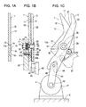
- Fig. 1C is a front view of a weft cutting device in which a movable cutter blade 2 is in an open state.
- Fig. 1B is a partially sectioned left side view of Fig. 1C.
- Fig. 1A is a sectional view of a fixed cutter blade 1 shown in Fig. 1B .
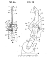
- Fig. 2B is a front view of the weft cutting device in which the movable cutter blade 2 is in a closed state.
- Fig. 2A is a partially sectioned left side view of Fig. 2B .
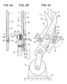
- Fig. 3 is a diagram illustrating the area in which a projecting portion 16 is formed.
- the weft cutting device is used as a yarn feed cutter for cutting a weft yarn after a weft insertion process, a selvage cutter disposed at a weft arrival side, a center selvage cutter for forming a multi-width cloth, etc. in a loom.
- the fixed cutter blade 1 and the movable cutter blade 2 are connected to each other and supported by a shaft member 3 such that the movable cutter blade 2 is rotatable with respect to the fixed cutter blade 1 around the shaft member 3.
- the movable cutter blade 2 is rotated by a rotating unit 4.
- the weft cutting device is attached to a frame 6 of the loom.
- the fixed cutter blade 1 includes an edge section 12 and a base section 13 which are formed of a continuous plate body
- the movable cutter blade 2 includes an edge section 22 and a base section 23 which are also formed of a continuous plate body.
- Shaft holes 14 and 24 are formed in the fixed cutter blade 1 and the movable cutter blade 2, respectively, such that rotational centers are disposed in the base sections 13 and 23 (in areas of the base sections 13 and 23 near the edge sections 12 and 22, respectively, in the figures).
- the shaft hole 24 in the movable cutter blade 2 is tapered such that the diameter thereof increases toward the outer side (toward the side opposite to the fixed cutter blade 1).
- the edge sections 12 and 22 have the edges 11 and 21, respectively, along end faces thereof. The edges 11 and 21 cross each other on the rotation plane, and a crossing point, that is, a crossing position, moves in a direction toward the weft yarn as the movable cutter blade 2 rotates. Thus, the weft yarn is cut.
- the shaft member 3 includes a pin 31 which extends through the two shaft holes 14 and 24, a nut 33 which is screwed onto an external thread 32 formed at an end of the pin 31, and a taper bush 34 brazed to the pin 31 at the other end thereof.
- the shaft member 3 serves to connect the movable cutter blade 2 to the fixed cutter blade 1 in a rotatable manner.
- the nut 33 retains the fixed cutter blade 1 at the outer side thereof (at the side opposite to the movable cutter blade 2), and the urging member 5 is placed between the nut 33 and the fixed cutter blade 1.
- the taper bush 34 is a ring that retains the movable cutter blade 2 at the outer side thereof (at the side opposite to the fixed cutter blade 1), and is brazed to the pin 31 while an end portion of the pin 31 extends through a through hole 35 formed in the taper bush 34 at an axial center thereof.
- the taper bush 34 is tapered such that the shape of the outer peripheral surface of the taper bush 34 corresponds to the shape of the shaft hole 24 formed in the movable cutter blade 2.
- the taper bush 34 is fitted to the shaft hole 24 in the movable cutter blade 2 along the tapered surface thereof, and an outer end portion of the taper bush 34 projects from the shaft hole 24.
- the taper bush 34 is made of a super hard metal and has an abrasion resistance, similar to the fixed cutter blade 1 and the movable cutter blade 2, and is brazed to the pin 31, which is made of structural steel.
- the urging member 5 includes a plurality of disc springs through which the external thread 32 of the pin 31 is inserted.
- the urging member 5 serves to urge the taper bush 34 on the pin 31 toward the fixed cutter blade 1 by being in contact with the nut 33 and a portion of the fixed cutter blade 1 that surrounds the shaft hole 14. Accordingly, the movable cutter blade 2 is pressed against the fixed cutter blade 1 by the taper bush 34.
- the four disc springs are divided into two pairs and are stacked on one another such that large-diameter portions of the disc springs face each other in each pair.
- the urging force of the urging member 5 can be adjusted by moving the nut 33 in the axial direction of the pin 31.
- the contact force between the movable cutter blade 2 and the fixed cutter blade 1 can be adjusted.
- the urging force of the urging member 5 is strong, a strong contact force is applied and the weft yarn is reliably cut without being allowed to escape between the edges 11 and 21.
- the amount of wear of the edges 11 and 21 increases.
- the contact force is also weak and the weft yarn easily escapes, which leads to weft cut failures.
- wear of the edges 11 and 21 can be suppressed.
- At least one of the fixed cutter blade 1 and the movable cutter blade 2 on which the projecting portion 16 is formed is the fixed cutter blade 1, and the projecting portion 16 is provided only on the fixed cutter blade 1.
- a surface (inner surface) of the fixed cutter blade 1 which faces the movable cutter blade 2 includes two flat surfaces sectioned from each other by a step 15.
- the flat surface on the side opposite to the edge section 12 with respect to the step 15 is defined as the projecting portion 16 that projects toward the movable cutter blade 2.
- the projecting portion 16 is formed in an area which is on the side opposite to the edge section 12 with respect to the rotational center and which constantly faces the movable cutter blade 2 while the movable cutter blade 2 is rotating.
- the area in which the projecting portion 16 is to be formed will be described below with reference to Fig. 3 .
- the case is considered in which one of the fixed cutter blade 1 and the movable cutter blade 2 on which the projecting portion 16 is formed is the fixed cutter blade 1.
- the area on the side opposite to the edge section 12 with respect to the rotational center is an area of the base section 13 of the fixed cutter blade 1 which is on the side opposite to the edge section 12 with respect to the rotational center while the movable cutter blade 2 rotates from the open state shown in Fig. 1C in which the movable cutter blade 2 is at a cutting-operation start position to the closed state shown in Fig. 2B in which the movable cutter blade 2 is at the cutting-operation end position.
- Fig. 1C in which the movable cutter blade 2 is at a cutting-operation start position
- Fig. 2B in which the movable cutter blade 2 is at the cutting-operation end position.
- the movable cutter blade 2 at the time when the cutting operation is started is drawn by the solid lines.
- a line is drawn between the rotational center O and a crossing point A between the edges 11 and 21 at the time when the cutting operation is started, and another line which is drawn so as to orthogonally intersect the above-mentioned line at the rotational center O divides the base section 13 of the fixed cutter blade 1 into two areas.
- One of the two areas that is on the side opposite to the edge section 12 is defined as a first area.
- the movable cutter blade 2 at the time when the cutting operation is ended is drawn by the two-dot dashed lines. Referring to Fig.
- a line is drawn between the rotational center O and a crossing point B between the edges 11 and 21 at the time when the cutting operation is ended, and another line which is drawn so as to orthogonally intersect the above-mentioned line at the rotational center O divides the base section 13 of the fixed cutter blade 1 into two areas.
- One of the two areas that is on the side opposite to the edge section 12 is defined as a second area.
- the overlapping area of the above-described first area and the second area is defined as the area on the side opposite to the edge section 12 with respect to the rotational center O.
- the area which constantly faces the movable cutter blade 2 while the movable cutter blade 2 rotates is a part of the above-described overlapping area which constantly faces the movable cutter blade 2 over the entire rotating process of the movable cutter blade 2 in which the movable cutter blade 2 moves from the cutting-operation start position to the cutting-operation end position and then returns from the cutting-operation end position to the cutting-operation start position.
- This area is shown as a shaded area in Fig. 3 , and the projecting portion 16 is formed in this area.
- the rotational direction of the movable cutter blade 2 is defined as a direction which is orthogonal to a bisector line of an angle between the line connecting the crossing point A and the rotational center O and the line connecting the crossing point B and the rotational center O.
- the projecting portion 16 extends beyond the above-described shaded area, and a portion of the projecting portion 16 which constantly faces the movable cutter blade 2 extends substantially entirely over the above-described shaded area in the rotational direction.
- the projecting portion 16 extends substantially entirely over the above-described shaded area which constantly faces the movable cutter blade 2 in the rotational direction.
- the projecting portion 16 having a sufficient length constantly faces the movable cutter blade 2 and smooth rotation of the movable cutter blade 2 can be ensured over the entire rotatable range thereof.
- the smooth rotation of the movable cutter blade 2 can be ensured over the entire rotatable range thereof as long as the projecting portion 16 extends over one-half or more of the above-described shaded area in the rotational direction.
- the case is considered in which one of the fixed cutter blade 1 and the movable cutter blade 2 on which the projecting portion 16 is formed is the fixed cutter blade 1.
- one of the fixed cutter blade 1 and the movable cutter blade 2 on which the projecting portion 16 is formed may also be the movable cutter blade 2, and the above discussion also applies to this case.
- the projecting portion 16 is a portion of the fixed cutter blade 1, and is formed by processing a plate body having a uniform thickness. More specifically, an inner surface of the plate body is initially flat over the entire area thereof. The plate body is subjected to a cutting (milling) process along a plane parallel to the initially flat inner surface so as to form a milled surface 17 by reducing the plate thickness in an area corresponding to the edge section 12 and a portion of the base section 13 surrounding the shaft area. As a result, the portion of the plate body in which the plate thickness is maintained serves as the projecting portion 16 which projects toward the movable cutter blade 2 after the assembly. The projecting portion 16 projects by an amount corresponding to the depth to which the milled surface 17 is cut, and the step 15 is formed between the projecting portion 16 and a surface 17a adjacent to the projecting portion 16.
- the milled surface 17 is formed as a single flat surface which continues to the edge section 12. However, it is not necessary that the milled surface 17 be a single flat surface as long as the milled surface 17 does not interfere with the movable cutter blade 2. More specifically, the milled surface 17 may be recessed in an area corresponding to the surface 17a adjacent to the projecting portion 16, or the plate thickness may be increased stepwise toward the projecting portion 16.
- Each countersunk screw 62 has a head portion 62a and a screw portion 62b which continues from the head portion 62a.
- the head portion 62a of each countersunk screw 62 is fitted to a corresponding receiving hole 18 formed in the end portion of the base section 13 of the fixed cutter blade 1, and the screw portion 62b of each countersunk screw 62 is screwed into a corresponding screw hole 61a formed in the cutter bracket 61.
- the head portion 62a is tapered such that the diameter thereof increases toward the movable cutter blade 2, and the receiving hole 18 therefor is also formed in a corresponding tapered shape.
- the head portion 62a is fixed in a manner such that the top surface thereof does not project from the inner surface of the projecting portion 16. Therefore, the head portion 62a is prevented from interfering with the movable cutter blade 2 when the movable cutter blade 2 rotates.
- the end surface of the head portion 62a may be on the same plane as the inner surface of the projecting portion 16. Alternatively, the head portion 62a may slightly project from the inner surface of the projecting portion 16 as long as the head portion 62a does not interfere with the movable cutter blade 2.
- a rotary solenoid 41 which function as a rotational drive source, is fixed to the frame 6, and a rotational shaft 42 of the rotary solenoid 41 is fixed to one end of a driving-force transmission lever 43.
- a roller 44 is rotatably supported at the other end of the driving-force transmission lever 43 in such a manner that the roller 44 is parallel with the rotational shaft 42. The roller 44 is engaged with an end portion of the base section 23 of the movable cutter blade 2.
- the end portion of the base section 23 of the movable cutter blade 2 is formed in a U-shape such that a U-shaped groove is formed therein, and the U-shaped groove serves as an engagement notch 45 which guides the roller 44 in a movable manner.
- the rotating unit 4 includes the above-described rotary solenoid 41, the rotational shaft 42, the driving-force transmission lever 43, the roller 44, and the engagement notch 45.
- the structure of the projecting portion 16 on the fixed cutter blade 1 differs from that according to the first embodiment.
- the fixed cutter blade 1 is formed by fixing and integrating two plates with each other.
- the two plates are a plate for forming the projecting portion 16 and a plate for forming a main body 1a other than the projecting portion 16.
- the projecting portion 16 is formed by fixing a plate that is different from the plate for forming the main body 1a, that is, a member for forming the base section 13, to the base section 13.
- the plate for forming the projecting portion 16 is fixed to the base section 13 in an area which is on the side opposite to the edge section 12 with respect to the rotational center and which constantly faces the movable cutter blade 2.
- the projecting portion 16 is formed of an elongate rectangular plate which extends beyond the rotatable range of the movable cutter blade 2 at both ends thereof and which is detachably fixed to the fixed cutter blade 1 with screws 19 at both ends thereof.
- the plate for forming the projecting portion 16 is thinner than head portions of the screws 19, and the head portions of the screws 19 cannot be embedded therein. Therefore, if, for example, the screws 19 are disposed in the rotatable range of the movable cutter blade 2, the function of the projecting portion 16 cannot be obtained. In addition, since the plate for forming the projecting portion 16 is thin and the thickness thereof is about 1 mm, it is not possible to form internal threads in the projecting portion 16. Therefore, it is not possible to fix the screws 19 by inserting the screws 19 into the fixed cutter blade 1 through the outer surface thereof and screwing the screws 19 into internal threads formed in the plate for forming the projecting portion 16.
- the ends of the projecting portion 16 are disposed in areas outside the rotatable range of the movable cutter blade 2 (in areas where interference with the movable cutter blade 2 does not occur).
- Through holes corresponding to internal threads 20 formed in the main body 1a are formed in the plate for forming the projecting portion 16 at both ends thereof.
- Wear of the plate for forming the projecting portion 16 can be suppressed if a plate made of a hard material, such as a stainless steel plate, is used, and wear of the movable cutter blade 2 can be prevented if a plate made of a low-friction material, such as a brass plate, is used.
- a plate made of a hard material such as a stainless steel plate
- a low-friction material such as a brass plate
- the projecting portion 16 may be formed of a single plate. Alternatively, the projecting portion 16 may also be formed by stacking a plurality of plates having the same thickness or different thicknesses.
- the weft cutting operation is performed as described below.
- the edges 11 and 21 cross each other on the rotation plane of the movable cutter blade 2, and a crossing position (crossing point) moves in a direction toward the weft yarn as the movable cutter blade 2 rotates.
- the weft yarn is cut.
- the edges 11 and 21 are spaced from each other by a maximum distance, as shown in Fig. 1 , and a weft yarn (not shown) is placed between the edges 11 and 21 in the open state.
- the rotary solenoid 41 is driven so as to rotate the movable cutter blade 2, and the edges 11 and 21 are moved toward each and become closed as shown in Fig. 2 , so that the weft yarn is cut.
- the movable cutter blade 2 is urged toward the fixed cutter blade 1 by the urging member 5 over the entire rotatable range of the movable cutter blade 2. Accordingly, the fixed cutter blade 1 and the movable cutter blade 2 are constantly in contact with each other at only two points, which are a position corresponding to the projecting portion 16 near the rotational center and the crossing position between the edges 11 and 21, while the distance between the inner surfaces of the fixed cutter blade 1 and the movable cutter blade 2 is limited by the shaft member 3.
- the projecting portion 16 may be provided on the movable cutter blade 2 instead of the fixed cutter blade 1.
- the projecting portion 16 may be formed on each of the fixed cutter blade 1 and the movable cutter blade 2.
- a coil spring may be used as the urging member 5 instead of the disc springs.
- the movable cutter blade 2 may be pressed against by the fixed cutter blade 1 by placing a plate spring on an outer surface of the movable cutter blade 2 and causing the plate spring to press the outer surface of the movable cutter blade 2. In either case, at least the edge section 22 of the movable cutter blade 2 is pressed against the fixed cutter blade 1 by the urging force applied by the urging member 5.
- each of the fixed cutter blade 1 and the movable cutter blade 2 is made of a single member, they may also be formed by integrating different members with bolts or the like.
- the edge sections 12 and 22 may be formed of a super hard material, and the fixed cutter blade 1 and the movable cutter blade 2 may be formed by fastening the edge sections 12 and 22 to the base sections 13 and 23, respectively, with bolts.
- the edges 11 and 21 of the edge sections 12 and 22, respectively may be formed of a super hard material and the edge sections 12 and 22 may be formed by fastening the edges to the main bodies with bolts or by fixing the edges to the main bodies by shrink fitting.
- the base section 13 may be, for example, formed by combining a first member which surrounds the rotational shaft and which is attached to the frame 6 and a second member which is connected to the first member and which continues to the edge section 12.
Landscapes
- Engineering & Computer Science (AREA)
- Textile Engineering (AREA)
- Looms (AREA)
Applications Claiming Priority (1)
| Application Number | Priority Date | Filing Date | Title |
|---|---|---|---|
| JP2008012462A JP2009174074A (ja) | 2008-01-23 | 2008-01-23 | 織機の緯糸切断装置 |
Publications (2)
| Publication Number | Publication Date |
|---|---|
| EP2083104A2 true EP2083104A2 (de) | 2009-07-29 |
| EP2083104A3 EP2083104A3 (de) | 2010-01-06 |
Family
ID=40561906
Family Applications (1)
| Application Number | Title | Priority Date | Filing Date |
|---|---|---|---|
| EP09000359A Withdrawn EP2083104A3 (de) | 2008-01-23 | 2009-01-13 | Schussfadenschneidvorrichtung für Webmaschine |
Country Status (3)
| Country | Link |
|---|---|
| EP (1) | EP2083104A3 (de) |
| JP (1) | JP2009174074A (de) |
| CN (1) | CN101492854B (de) |
Cited By (4)
| Publication number | Priority date | Publication date | Assignee | Title |
|---|---|---|---|---|
| CN102560837A (zh) * | 2012-02-18 | 2012-07-11 | 常州同维佳业新材料科技有限公司 | 一种剑杆织机用的纬纱热剪刀 |
| US9457178B2 (en) | 2010-05-18 | 2016-10-04 | Zoll Medical Corporation | Wearable therapeutic device system |
| US11571561B2 (en) | 2019-10-09 | 2023-02-07 | Zoll Medical Corporation | Modular electrical therapy device |
| US12403322B2 (en) | 2021-02-08 | 2025-09-02 | Zoll Medical Corporation | Modular ingress protected electrode system for a wearable defibrillator |
Families Citing this family (1)
| Publication number | Priority date | Publication date | Assignee | Title |
|---|---|---|---|---|
| CN102418223A (zh) * | 2010-09-28 | 2012-04-18 | 海泰纺织(苏州)有限公司 | 织机废边收集装置 |
Citations (1)
| Publication number | Priority date | Publication date | Assignee | Title |
|---|---|---|---|---|
| JP2000328398A (ja) | 1999-05-24 | 2000-11-28 | Toyota Autom Loom Works Ltd | 織機における緯糸切断装置 |
Family Cites Families (5)
| Publication number | Priority date | Publication date | Assignee | Title |
|---|---|---|---|---|
| GB708743A (en) * | 1951-07-24 | 1954-05-12 | John Stansfield And Son Ltd | A loom weft cutter |
| JPS4715659Y1 (de) * | 1969-06-25 | 1972-06-02 | ||
| FR2306291A1 (fr) * | 1975-04-03 | 1976-10-29 | Lebocey Industrie | Dispositif coupe-pince fil de metier a tisser passe-trame, ainsi que les metiers a tisser passe-trame pourvus de ce dispositif |
| JP3598670B2 (ja) * | 1996-08-30 | 2004-12-08 | 株式会社豊田自動織機 | 織機における緯糸切断装置 |
| JP2003221761A (ja) * | 2002-01-28 | 2003-08-08 | Toyota Industries Corp | 織機における緯糸切断装置 |
-
2008
- 2008-01-23 JP JP2008012462A patent/JP2009174074A/ja active Pending
-
2009
- 2009-01-13 EP EP09000359A patent/EP2083104A3/de not_active Withdrawn
- 2009-01-21 CN CN2009100048599A patent/CN101492854B/zh not_active Expired - Fee Related
Patent Citations (1)
| Publication number | Priority date | Publication date | Assignee | Title |
|---|---|---|---|---|
| JP2000328398A (ja) | 1999-05-24 | 2000-11-28 | Toyota Autom Loom Works Ltd | 織機における緯糸切断装置 |
Cited By (11)
| Publication number | Priority date | Publication date | Assignee | Title |
|---|---|---|---|---|
| US9457178B2 (en) | 2010-05-18 | 2016-10-04 | Zoll Medical Corporation | Wearable therapeutic device system |
| US9956392B2 (en) | 2010-05-18 | 2018-05-01 | Zoll Medical Corporation | Wearable therapeutic device |
| US10183160B2 (en) | 2010-05-18 | 2019-01-22 | Zoll Medical Corporation | Wearable therapeutic device |
| US10589083B2 (en) | 2010-05-18 | 2020-03-17 | Zoll Medical Corporation | Wearable therapeutic device |
| US11278714B2 (en) | 2010-05-18 | 2022-03-22 | Zoll Medical Corporation | Wearable therapeutic device |
| US11872390B2 (en) | 2010-05-18 | 2024-01-16 | Zoll Medical Corporation | Wearable therapeutic device |
| US11975186B2 (en) | 2010-05-18 | 2024-05-07 | Zoll Medical Corporation | Wearable therapeutic device |
| CN102560837A (zh) * | 2012-02-18 | 2012-07-11 | 常州同维佳业新材料科技有限公司 | 一种剑杆织机用的纬纱热剪刀 |
| US11571561B2 (en) | 2019-10-09 | 2023-02-07 | Zoll Medical Corporation | Modular electrical therapy device |
| US12311163B2 (en) | 2019-10-09 | 2025-05-27 | Zoll Medical Corporation | Modular electrical therapy device |
| US12403322B2 (en) | 2021-02-08 | 2025-09-02 | Zoll Medical Corporation | Modular ingress protected electrode system for a wearable defibrillator |
Also Published As
| Publication number | Publication date |
|---|---|
| JP2009174074A (ja) | 2009-08-06 |
| EP2083104A3 (de) | 2010-01-06 |
| CN101492854B (zh) | 2012-01-11 |
| CN101492854A (zh) | 2009-07-29 |
Similar Documents
| Publication | Publication Date | Title |
|---|---|---|
| EP2083104A2 (de) | Schussfadenschneidvorrichtung für Webmaschine | |
| US9206840B2 (en) | Radial foil bearing | |
| US8231320B2 (en) | Countersunk head screw | |
| KR101796846B1 (ko) | 축방향 위치 조정 장치를 갖는 절삭 공구 | |
| KR102076027B1 (ko) | 미세-조정을 위해 구성되는 슬리팅 공구 | |
| JPH0123251B2 (de) | ||
| RU2650365C2 (ru) | Зуборезная фреза с радиально регулируемыми стержневыми резцами | |
| US20090090008A1 (en) | Cutter | |
| JP6894499B2 (ja) | ティルティングパッド軸受 | |
| JP2019155490A (ja) | スリッタ装置 | |
| KR20140002596A (ko) | 베어링 쉘의 구조화된 슬라이딩 면 | |
| KR20160110939A (ko) | 프레싱 장치 | |
| US20050113003A1 (en) | Method for forming a cutting edge along an edge portion of a blade stock | |
| JP3382585B2 (ja) | 軸継手 | |
| US8925419B2 (en) | Compliant cam with flexure cam arm | |
| US6415695B1 (en) | Method for forming spherical concave surfaces | |
| CN109773221B (zh) | 切削用加工工具 | |
| CH706901B1 (fr) | Arbre de barillet d'horlogerie. | |
| US20070251095A1 (en) | Cutter | |
| JP4826227B2 (ja) | ロータリーダイ | |
| JP5357001B2 (ja) | トルク調整式トルクリミッタ | |
| JP2021094675A (ja) | スリッタ装置 | |
| JP3227397U (ja) | 強固に組立てられたカッター保持アセンブリ | |
| KR102287055B1 (ko) | 면취기 가이드 및 면취기 가이드를 포함하는 면취기 | |
| JPH0141523Y2 (de) |
Legal Events
| Date | Code | Title | Description |
|---|---|---|---|
| PUAI | Public reference made under article 153(3) epc to a published international application that has entered the european phase |
Free format text: ORIGINAL CODE: 0009012 |
|
| AK | Designated contracting states |
Kind code of ref document: A2 Designated state(s): AT BE BG CH CY CZ DE DK EE ES FI FR GB GR HR HU IE IS IT LI LT LU LV MC MK MT NL NO PL PT RO SE SI SK TR |
|
| AX | Request for extension of the european patent |
Extension state: AL BA RS |
|
| PUAL | Search report despatched |
Free format text: ORIGINAL CODE: 0009013 |
|
| AK | Designated contracting states |
Kind code of ref document: A3 Designated state(s): AT BE BG CH CY CZ DE DK EE ES FI FR GB GR HR HU IE IS IT LI LT LU LV MC MK MT NL NO PL PT RO SE SI SK TR |
|
| AX | Request for extension of the european patent |
Extension state: AL BA RS |
|
| AKY | No designation fees paid | ||
| STAA | Information on the status of an ep patent application or granted ep patent |
Free format text: STATUS: THE APPLICATION IS DEEMED TO BE WITHDRAWN |
|
| 18D | Application deemed to be withdrawn |
Effective date: 20100707 |
|
| REG | Reference to a national code |
Ref country code: DE Ref legal event code: 8566 |