EP2083177A2 - Cylindre hydraulique avec une tige dotée d'un dispositif de sécurité - Google Patents
Cylindre hydraulique avec une tige dotée d'un dispositif de sécurité Download PDFInfo
- Publication number
- EP2083177A2 EP2083177A2 EP09000389A EP09000389A EP2083177A2 EP 2083177 A2 EP2083177 A2 EP 2083177A2 EP 09000389 A EP09000389 A EP 09000389A EP 09000389 A EP09000389 A EP 09000389A EP 2083177 A2 EP2083177 A2 EP 2083177A2
- Authority
- EP
- European Patent Office
- Prior art keywords
- rod
- rod body
- rod head
- head
- joint
- Prior art date
- Legal status (The legal status is an assumption and is not a legal conclusion. Google has not performed a legal analysis and makes no representation as to the accuracy of the status listed.)
- Withdrawn
Links
- 238000003466 welding Methods 0.000 claims abstract description 24
- 230000007547 defect Effects 0.000 description 7
- 230000006835 compression Effects 0.000 description 3
- 238000007906 compression Methods 0.000 description 3
- 238000005452 bending Methods 0.000 description 2
- 238000010276 construction Methods 0.000 description 2
- 238000007792 addition Methods 0.000 description 1
- 230000004048 modification Effects 0.000 description 1
- 238000012986 modification Methods 0.000 description 1
- 238000006467 substitution reaction Methods 0.000 description 1
Images


Classifications
-
- F—MECHANICAL ENGINEERING; LIGHTING; HEATING; WEAPONS; BLASTING
- F15—FLUID-PRESSURE ACTUATORS; HYDRAULICS OR PNEUMATICS IN GENERAL
- F15B—SYSTEMS ACTING BY MEANS OF FLUIDS IN GENERAL; FLUID-PRESSURE ACTUATORS, e.g. SERVOMOTORS; DETAILS OF FLUID-PRESSURE SYSTEMS, NOT OTHERWISE PROVIDED FOR
- F15B15/00—Fluid-actuated devices for displacing a member from one position to another; Gearing associated therewith
- F15B15/08—Characterised by the construction of the motor unit
- F15B15/14—Characterised by the construction of the motor unit of the straight-cylinder type
- F15B15/1423—Component parts; Constructional details
- F15B15/1457—Piston rods
-
- E—FIXED CONSTRUCTIONS
- E02—HYDRAULIC ENGINEERING; FOUNDATIONS; SOIL SHIFTING
- E02F—DREDGING; SOIL-SHIFTING
- E02F9/00—Component parts of dredgers or soil-shifting machines, not restricted to one of the kinds covered by groups E02F3/00 - E02F7/00
- E02F9/20—Drives; Control devices
-
- F—MECHANICAL ENGINEERING; LIGHTING; HEATING; WEAPONS; BLASTING
- F15—FLUID-PRESSURE ACTUATORS; HYDRAULICS OR PNEUMATICS IN GENERAL
- F15B—SYSTEMS ACTING BY MEANS OF FLUIDS IN GENERAL; FLUID-PRESSURE ACTUATORS, e.g. SERVOMOTORS; DETAILS OF FLUID-PRESSURE SYSTEMS, NOT OTHERWISE PROVIDED FOR
- F15B15/00—Fluid-actuated devices for displacing a member from one position to another; Gearing associated therewith
- F15B15/08—Characterised by the construction of the motor unit
- F15B15/14—Characterised by the construction of the motor unit of the straight-cylinder type
Definitions
- the present invention relates to a hydraulic cylinder having a rod safety device, which can improve the safety of a hydraulic cylinder by adding a joint connection means to a bonding part in which a rod head and a rod body of the hydraulic cylinder are joint-connected by welding.
- the present invention relates to a hydraulic cylinder having a rod safety device, in which a screw engagement part (e.g. a screw is used) is formed in center parts of mutual contact surfaces of a rod head and a rod body of the hydraulic cylinder in a shaft direction, and an outer surface of a joint connection part of the rod head and the rod body is welded, so that a free falling of an arm and a bucket is prevented by a screw engagement part when a welding part is broken to protect a cab and an operator.
- a screw engagement part e.g. a screw is used
- a general hydraulic cylinder includes a tube 2 accommodating a cylinder rod 1 that slides in a set stroke range; a cover 3 connected by weld joint to one end part of the tube 2 (corresponding to a side of a rod head 1a); an end cover 4 connected by weld joint to the other end part of the tube 3 (corresponding to a side of a piston 5); and a piston 5 fastened to one end part of the cylinder rod 1 to reciprocate along an inner periphery of the tube 2.
- the cylinder rod 1 receives a complex load, such as a tensile force, a compression force, and a bending load in a shaft direction.
- a complex load such as a tensile force, a compression force, and a bending load in a shaft direction.
- a relatively large force acts on the outer surface (i.e. an edge part) of the weld joint part 13 of the rod body 1b rather than the center of the weld joint part 13 in the shaft direction.
- an owner of the equipment may mount a working device optionally remodeled to cope with diverse working environments (so called "special attachments") on a bucket 7 and so on.
- the present invention has been made to solve the above-mentioned problems occurring in the prior art while advantages achieved by the prior art are maintained intact.
- One object of the present invention is to provide a hydraulic cylinder having a rod safety device, in which a screw engagement part is formed in center parts of mutual contact surfaces of a rod head and a rod body of the hydraulic cylinder in a shaft direction, and an outer surface of a joint connection part of the rod head and the rod body is welded, so that a free falling of an arm and a bucket is prevented by fastening members when a welding part is broken to prevent the damage of a cab and to protect an operator from an accident.
- Another object of the present invention is to provide a hydraulic cylinder having a rod safety device, which can improve the reliability of equipment by preventing a free falling of an arm and a bucket when a welding part of a cylinder rod is broken due to welding defects and so on, even if an owner of the equipment optionally remodels a working device to cope with divers working environments.
- a hydraulic cylinder having a rod safety device which includes a cylinder rod sliding within a set stroke range in a tube and composed of a rod head and a rod body joint-connected to the rod head; a cover connected by weld joint to one end part of the tube; an end cover connected by weld joint to the other end part of the tube; a piston fastened to one end part of the cylinder rod to reciprocate along an inner periphery of the tube; and a connection means composed of a screw engagement part formed in center parts of mutual contact surfaces of the rod head and the rod body in a shaft direction to joint-connect the rod head and the rod body by screw-engaging the rod head and the rod body, and a weld joint part joint-connecting the rod head and the rod body by welding outer peripheries of the contact surfaces of the rod head and the rod body.
- the screw engagement part may include screw holes respectively formed in the center parts of the mutual contact surfaces of the rod head and the rod body in the shaft direction, and a connection bolt engaged into the screw holes to screw-engage the rod head and the rod body.
- the screw engagement part may include a screw hole formed in one of the center parts of the contact surfaces of the rod head and the rod body, and a connection bolt fixed by welding to the other of the center parts of the contact surfaces of the rod head and the rod body to correspond to the screw hole.
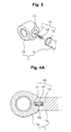
- a hydraulic cylinder having a rod safety device includes a cylinder rod 1 sliding within a set stroke range in a tube 2 and composed of a rod head 1a and a rod body 1b joint-connected to the rod head 1a; a cover 3 connected by weld joint to one end part of the tube 2; an end cover 4 connected by weld joint to the other end part of the tube 2; a piston 5 fastened to one end part of the cylinder rod 1 to reciprocate along an inner periphery of the tube 2; and a connection means composed of a screw engagement part 10 formed in center parts of mutual contact surfaces of the rod head 1a and the rod body 1b in a shaft direction to joint-connect the rod head 1a and the rod body 1b by screw-engaging the rod head 1a and the rod body 1b, and a weld joint part 13 joint-connecting the rod head 1a and the rod body 1b by welding outer peripheries of the contact surfaces of the
- the screw engagement part 10 includes screw holes 11 respectively formed in the center parts of the mutual contact surfaces of the rod head 1a and the rod body 1b in the shaft direction, and a connection bolt 12 engaged into the screw holes 11 to screw-engage the rod head 1a and the rod body 1b.
- the hydraulic cylinder having a rod safety device except for the screw engagement part 10 including the screw holes 11 respectively formed in the center parts of the mutual contact surfaces of the rod head 1a and the rod body 1b in the shaft direction, and the connection bolt 12 engaged into the screw holes 11 to screw-engage the rod head 1a and the rod body 1b, is substantially the same as the conventional hydraulic cylinder as illustrated in FIGS. 1 and 2 , and thus the detailed description thereof will be omitted.
- the same drawing reference numerals are used for the same elements across various figures.
- the rod head 1a and the rod body 1b are joint-connected by screw-engaging the connection bolt 12 into the screw holes 11 respectively formed in the center parts of the mutual contact surfaces of the rod head 1a and rod body 1b of the cylinder rod 1.
- the outer surfaces of the contact surfaces of the rod head 1a and the rod body 1b, which are in close contact with each other and are joint-connected by the connection bolt 12, are fixed together by welding.
- the rod head 1a and the rod body 1b are firstly joint-connected by the connection bolt 12 that is screw-engaged with the center parts of the mutual contact surfaces of the rod head and the rod body in a shaft direction, and are secondly joint-connected by the weld joint part 13 that fixes by welding the outer surfaces of the contact surfaces of the rod head 1a and the rod body 1b to each other.
- the weld joint part 13 may be broken or damaged due to welding defects and so on.
- the rod head 1a and the rod body 1b can be kept in a joint connection state by the connection bolt 12 that is screw-engaged with the inner center portion of the weld joint part 13 in a shaft direction.
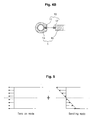
- the screw engagement part 10 which is formed in the center parts of the mutual contact surfaces of the rod head 1a and the rod body 1b in a shaft direction to joint-connect the rod head 1a and the rod body 1b through screw-engagement, may a screw hole 11 formed in one of the center parts of the contact surfaces of the rod head 1a and the rod body 1b (e.g. formed in the rod head 1a), and a connection bolt 12 fixed by welding to the other of the center parts of the contact surfaces of the rod head 1a and the rod body 1b to correspond to the screw hole 11.
- the construction except for the screw engagement part 10 composed of the screw hole 11 formed in the center of the contact surface of the rod head 1a and the connection bolt 12 fixed by welding to the center of the contact surface of the rod body 1a, is substantially the same as that as illustrated in FIGS. 3 and 4A , the detailed description thereof will be omitted.
- the same drawing reference numerals are used for the same elements across various figures.
- the hydraulic cylinder having a rod safety device has the following advantages.
- the screw engagement part is formed in the center parts of the mutual contact surfaces of the rod head and the rod body of the hydraulic cylinder in the shaft direction (i.e. in a direction of extension and compression of the cylinder rod), and the outer surface of the joint connection part of the rod head and the rod body is welded, a free falling of the arm and the bucket is prevented by the fastening members when the welding part is broken, so that the cab is prevented from being damaged, and the operator is protected from an accident.
- the reliability of the equipment is improved by preventing a free falling of the arm and the bucket when the welding part of the cylinder rod is broken due to welding defects and so on.
Landscapes
- Engineering & Computer Science (AREA)
- General Engineering & Computer Science (AREA)
- Physics & Mathematics (AREA)
- Fluid Mechanics (AREA)
- Mechanical Engineering (AREA)
- Mining & Mineral Resources (AREA)
- Civil Engineering (AREA)
- Structural Engineering (AREA)
- Actuator (AREA)
Applications Claiming Priority (1)
| Application Number | Priority Date | Filing Date | Title |
|---|---|---|---|
| KR1020080007192A KR20090081223A (ko) | 2008-01-23 | 2008-01-23 | 로드의 안전장치가 구비된 유압실린더 |
Publications (1)
| Publication Number | Publication Date |
|---|---|
| EP2083177A2 true EP2083177A2 (fr) | 2009-07-29 |
Family
ID=40598475
Family Applications (1)
| Application Number | Title | Priority Date | Filing Date |
|---|---|---|---|
| EP09000389A Withdrawn EP2083177A2 (fr) | 2008-01-23 | 2009-01-14 | Cylindre hydraulique avec une tige dotée d'un dispositif de sécurité |
Country Status (5)
| Country | Link |
|---|---|
| US (1) | US20090185887A1 (fr) |
| EP (1) | EP2083177A2 (fr) |
| JP (1) | JP2009174718A (fr) |
| KR (1) | KR20090081223A (fr) |
| CN (1) | CN101493107A (fr) |
Families Citing this family (1)
| Publication number | Priority date | Publication date | Assignee | Title |
|---|---|---|---|---|
| JP6521050B2 (ja) * | 2015-02-16 | 2019-05-29 | 株式会社タダノ | 液圧シリンダ、シリンダ装置、作業車両、及び液圧シリンダ製造方法 |
Family Cites Families (2)
| Publication number | Priority date | Publication date | Assignee | Title |
|---|---|---|---|---|
| US2599082A (en) * | 1947-10-03 | 1952-06-03 | Neal H Anderson Oil Tool Co | Slush pump piston and piston rod |
| US4741254A (en) * | 1986-06-12 | 1988-05-03 | Taylor Julian S | Pump plunger |
-
2008
- 2008-01-23 KR KR1020080007192A patent/KR20090081223A/ko not_active Ceased
-
2009
- 2009-01-13 US US12/352,638 patent/US20090185887A1/en not_active Abandoned
- 2009-01-14 EP EP09000389A patent/EP2083177A2/fr not_active Withdrawn
- 2009-01-21 JP JP2009010575A patent/JP2009174718A/ja active Pending
- 2009-01-22 CN CNA2009100060270A patent/CN101493107A/zh active Pending
Also Published As
| Publication number | Publication date |
|---|---|
| JP2009174718A (ja) | 2009-08-06 |
| US20090185887A1 (en) | 2009-07-23 |
| CN101493107A (zh) | 2009-07-29 |
| KR20090081223A (ko) | 2009-07-28 |
Similar Documents
| Publication | Publication Date | Title |
|---|---|---|
| US7445272B2 (en) | Upper frame structure for supporting cab of construction machinery | |
| US8491251B2 (en) | Gripping device of working machine and working machine with the same | |
| US7987942B2 (en) | Upper frame for excavator | |
| US20120189380A1 (en) | A coupler | |
| KR20220169029A (ko) | 어태치먼트 장착해제 식별 기능을 갖는 굴착기용 회전식 퀵커플러 | |
| EP2933388B1 (fr) | Protection de vérin hydraulique | |
| US20090180205A1 (en) | Construction equipment having side mirror fixing means | |
| EP2083177A2 (fr) | Cylindre hydraulique avec une tige dotée d'un dispositif de sécurité | |
| JP2009274828A (ja) | グラップルシリンダおよびグラップル | |
| JP5526106B2 (ja) | 建設機械のシリンダカバー取り付け構造 | |
| JP7715663B2 (ja) | 建設機械 | |
| CN213144940U (zh) | 一种带保护套的变幅伸缩油缸 | |
| KR102383283B1 (ko) | 중장비 공구용 방진장치의 결합구조 | |
| US8770908B2 (en) | Tilt cylinder support structure | |
| CN109296014B (zh) | 用于将臂联接于作业工具的联接器组件 | |
| KR101061697B1 (ko) | 유압 실린더의 커버 장치 | |
| US11718971B2 (en) | Excavator arm | |
| JP2020060082A (ja) | 作業機械シリンダロッドの保護装置 | |
| JP2007107314A (ja) | シリンダ装置 | |
| AU2020292108B2 (en) | Torque element and system for absorbing shear forces in a bolt con¬ nection for connecting a bucket element in a loading machine bucket | |
| KR100897532B1 (ko) | 중장비용 어태치먼트의 투스 장치 | |
| JP2019124071A (ja) | 油圧ショベル | |
| JP3104781B2 (ja) | シリンダ装置 | |
| KR101343653B1 (ko) | 산업용 차량의 리플렉터 조립체 | |
| JP4920570B2 (ja) | 建設機械におけるキャブ補強構造 |
Legal Events
| Date | Code | Title | Description |
|---|---|---|---|
| PUAI | Public reference made under article 153(3) epc to a published international application that has entered the european phase |
Free format text: ORIGINAL CODE: 0009012 |
|
| AK | Designated contracting states |
Kind code of ref document: A2 Designated state(s): AT BE BG CH CY CZ DE DK EE ES FI FR GB GR HR HU IE IS IT LI LT LU LV MC MK MT NL NO PL PT RO SE SI SK TR |
|
| AX | Request for extension of the european patent |
Extension state: AL BA RS |
|
| STAA | Information on the status of an ep patent application or granted ep patent |
Free format text: STATUS: THE APPLICATION HAS BEEN WITHDRAWN |
|
| 18W | Application withdrawn |
Effective date: 20091221 |