EP2083181B1 - Développements de ou associés à l'équilibrage d'un ensemble rotatif - Google Patents
Développements de ou associés à l'équilibrage d'un ensemble rotatif Download PDFInfo
- Publication number
- EP2083181B1 EP2083181B1 EP08019252A EP08019252A EP2083181B1 EP 2083181 B1 EP2083181 B1 EP 2083181B1 EP 08019252 A EP08019252 A EP 08019252A EP 08019252 A EP08019252 A EP 08019252A EP 2083181 B1 EP2083181 B1 EP 2083181B1
- Authority
- EP
- European Patent Office
- Prior art keywords
- axis
- rotating
- rotating assembly
- geometric axis
- relative
- Prior art date
- Legal status (The legal status is an assumption and is not a legal conclusion. Google has not performed a legal analysis and makes no representation as to the accuracy of the status listed.)
- Not-in-force
Links
- 238000011161 development Methods 0.000 title description 2
- 230000018109 developmental process Effects 0.000 title description 2
- 238000000034 method Methods 0.000 claims description 11
- 230000003068 static effect Effects 0.000 description 4
- 238000003754 machining Methods 0.000 description 2
- 230000000712 assembly Effects 0.000 description 1
- 238000000429 assembly Methods 0.000 description 1
- 238000010586 diagram Methods 0.000 description 1
- 238000005516 engineering process Methods 0.000 description 1
- 238000002955 isolation Methods 0.000 description 1
Images


Classifications
-
- F—MECHANICAL ENGINEERING; LIGHTING; HEATING; WEAPONS; BLASTING
- F16—ENGINEERING ELEMENTS AND UNITS; GENERAL MEASURES FOR PRODUCING AND MAINTAINING EFFECTIVE FUNCTIONING OF MACHINES OR INSTALLATIONS; THERMAL INSULATION IN GENERAL
- F16C—SHAFTS; FLEXIBLE SHAFTS; ELEMENTS OR CRANKSHAFT MECHANISMS; ROTARY BODIES OTHER THAN GEARING ELEMENTS; BEARINGS
- F16C3/00—Shafts; Axles; Cranks; Eccentrics
- F16C3/04—Crankshafts, eccentric-shafts; Cranks, eccentrics
- F16C3/20—Shape of crankshafts or eccentric-shafts having regard to balancing
-
- F—MECHANICAL ENGINEERING; LIGHTING; HEATING; WEAPONS; BLASTING
- F16—ENGINEERING ELEMENTS AND UNITS; GENERAL MEASURES FOR PRODUCING AND MAINTAINING EFFECTIVE FUNCTIONING OF MACHINES OR INSTALLATIONS; THERMAL INSULATION IN GENERAL
- F16D—COUPLINGS FOR TRANSMITTING ROTATION; CLUTCHES; BRAKES
- F16D3/00—Yielding couplings, i.e. with means permitting movement between the connected parts during the drive
- F16D3/02—Yielding couplings, i.e. with means permitting movement between the connected parts during the drive adapted to specific functions
- F16D3/04—Yielding couplings, i.e. with means permitting movement between the connected parts during the drive adapted to specific functions specially adapted to allow radial displacement, e.g. Oldham couplings
-
- F—MECHANICAL ENGINEERING; LIGHTING; HEATING; WEAPONS; BLASTING
- F16—ENGINEERING ELEMENTS AND UNITS; GENERAL MEASURES FOR PRODUCING AND MAINTAINING EFFECTIVE FUNCTIONING OF MACHINES OR INSTALLATIONS; THERMAL INSULATION IN GENERAL
- F16D—COUPLINGS FOR TRANSMITTING ROTATION; CLUTCHES; BRAKES
- F16D3/00—Yielding couplings, i.e. with means permitting movement between the connected parts during the drive
- F16D3/02—Yielding couplings, i.e. with means permitting movement between the connected parts during the drive adapted to specific functions
- F16D3/06—Yielding couplings, i.e. with means permitting movement between the connected parts during the drive adapted to specific functions specially adapted to allow axial displacement
-
- F—MECHANICAL ENGINEERING; LIGHTING; HEATING; WEAPONS; BLASTING
- F16—ENGINEERING ELEMENTS AND UNITS; GENERAL MEASURES FOR PRODUCING AND MAINTAINING EFFECTIVE FUNCTIONING OF MACHINES OR INSTALLATIONS; THERMAL INSULATION IN GENERAL
- F16F—SPRINGS; SHOCK-ABSORBERS; MEANS FOR DAMPING VIBRATION
- F16F15/00—Suppression of vibrations in systems; Means or arrangements for avoiding or reducing out-of-balance forces, e.g. due to motion
- F16F15/32—Correcting- or balancing-weights or equivalent means for balancing rotating bodies, e.g. vehicle wheels
- F16F15/322—Correcting- or balancing-weights or equivalent means for balancing rotating bodies, e.g. vehicle wheels the rotating body being a shaft
Definitions
- the present invention relates to a rotating arrangement comprising a rotating assembly mounted on a bearing, for example a rotor assembly in a gas turbine, and more particularly to developments in or relating to the balancing of such a rotating assembly.
- United States Patent No. 5259677 (Degrange et al ) describes a means of balancing a shaft mounted in an eccentric sleeve, the sleeve being supported on bearings.
- the eccentric sleeve is provided with weighted lobes at either end.
- the lobes are held in a fixed relationship relative to one another and the shaft.
- the lobes have a mass distribution such that any dynamic imbalance resulting from the rotating sleeve is offset and cancelled.
- Rotating components can be balanced by re-distributing the mass of the component so that the centre of mass of the component coincides with the geometric axis of rotation of the component.
- a common method of re-distributing the mass of the component, in order to balance the component, is to add material to the component or to remove material from the component.
- each of these methods carries an associated weight penalty, which can be particularly critical in, for example, aerospace applications.
- this weight penalty arises from the fact that the component must initially be provided with additional, sacrificial material that can be removed for balancing purposes, but which almost inevitably is not entirely removed during the balancing process.
- the weight penalty associated with balancing of rotating components can be reduced to a certain extent using so-called "mass centring" balancing methods, which involve machining the location features of the component according to an offset calculated following an initial balancing operation, such that the position of the geometric axis of rotation (defined by the location features) is made to be coincident with the centre of mass of the component.
- mass centring balancing methods have the disadvantage that machining of the location features is permanent.
- a rotating assembly mounted on an associated bearing defining a geometric axis of rotation for the rotating assembly, the rotating assembly comprising:
- the bearing may be a circular ring bearing defining the geometric axis and the first part may be an outer eccentric support member rotatably mounted concentrically within the ring bearing, the second part being rotatably supported inside the outer eccentric support member for said angular adjustment relative to the outer eccentric support member, about the second axis.
- the second part is an inner eccentric support member nested within the outer eccentric support member, the third part being rotatably supported inside the inner eccentric member for said independent, angular adjustment relative to the inner eccentric support member, about the third axis.
- the first, second and third parts need not be co-planar, and can be displaced along the geometric axis of rotation of the assembly.
- the distance between the second axis and the geometric axis is substantially equal to the distance between the third axis and the second axis.
- the rotatating assembly is mounted on a spaced-apart pair of said bearings and the rotating assembly comprises a corresponding pair of said first parts and corresponding pair of said second parts, the respective axial ends of said third part being engaged with the second parts, whereby the rotating arrangement is configured such that opposing angular adjustment of the second parts relative to the respective first parts will adjust the principal inertia axis to be aligned with, or parallel to, the geometric axis of rotation.
- the third part may be a sub-assembly comprising at least two assembled components, for example a rotor assembly.
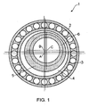
- Figure 1 shows a rotating arrangement 1 comprising a generally planar bearing 2, in this case a circular ball-bearing.
- a generally planar bearing 2 in this case a circular ball-bearing.
- the bearing 2 is shown only diagrammatically and in isolation in Figure 1 , but in practice may form part of a larger assembly such as, for example, a gas turbine or the like.
- a rotating assembly 3 is mounted to the bearing 2 and comprises three parts:
- the rotating assembly 3 is rotated about a geometric axis of rotation A, at the centre of the bearing 2, by rotating the outer eccentric annular member 4 relative to the bearing 2.
- the centre-of-mass of the rotating assembly 3 is co-incident with the geometric axis of rotation A and therefore, where the initial mass distribution of the rotating assembly 3 is such that the centre-of-mass is offset from the geometric axis of rotation A, the centre-of-mass needs to be adjusted so that as far as possible it is co-incident with the geometric axis of rotation A.
- Figure 2 illustrates how independent angular adjustment of the annular members 4, 5 and the third part 6 can be used to adjust the centre-of-mass of the rotating assembly 3, relative to the geometric axis of rotation A, with the aim of positioning the centre-of-mass of the rotating assembly 3 on the geometric axis of rotation A.
- the distance between the third axis C and the geometric axis A can be adjusted between a lower limit r (see the position C" for the axis C in Figure 2 ) and an upper limit R (see the position C' for the axis C in Figure 2 ).
- a lower limit r see the position C" for the axis C in Figure 2
- an upper limit R see the position C' for the axis C in Figure 2 .
- the centre-of-mass and geometric axis A can be positioned at the same radial distance from the axis C.
- the third part 6 can then be independently rotated relative to the combination of the bearing 2 and annular members 4,5 (ie whilst maintaining the bearing 2 and annular members 4,5 in fixed angular position with respect to one another) to adjust the angular position of the centre-of mass and geometric axis A about the axis C until the centre-of-mass and geometric axis A are co-incident.
- the third axis C can be adjusted to the position C' at a distance R from the geometric axis A (by relatively adjusting the annular members 4,5 in the manner described) and then the centre of mass F and geometric axis A can be angularly adjusted along the dotted path 8 (by rotating the third part 6 about the axis C) to bring the centre-of-mass into coincidence with the geometric axis A.
- the third axis C can be adjusted to the position C", at a distance r from the geometric axis A, and then the centre-of-mass G and geometric axis A can be angularly adjusted along the dotted path 9, about the axis C, to bring the centre-of-mass G into co-incidence with the geometric axis A.
- the parameter r is a function of the relative positions of the axes A, B and C, and therefore its value can be minimised as far as possible within specified tolerances. Indeed, it is envisaged that, by equating the (fixed) radial distance of each of the axes A, C relative to the axis B, r can be made to be zero.
- Figures 3a and 3b show an alternative rotating assembly 10 comprising a first part 11, second part 12 and a third part 13 which are displaced along a geometric axis A.
- Figures 3a and 3b are merely schematic and are intended to illustrate the underlying principal of the invention.
- the precise overall shape of the various parts 11, 12 and 13 may vary in practice and the parts might form part of any number of different possible rotating assemblies such as, for example a rotor assembly in a gas turbine application.
- the first part 11 might generally be described as an "eccentric cylinder", in the sense that it comprises a first cylindrical section 11a configured to be mounted on an associated bearing (not shown) for rotation, relative to the bearing, about the geometric axis A shown in Figure 3a , and a second cylindrical section 11b fixed to the cylindrical section 11a and centred on a second (longitudinal) axis B eccentric to the geometric axis A.
- the second part 12 is also generally cylindrical and comprises a cylindrical bore 12a corresponding in dimensions to the second cylindrical section 11b on the first part 11. As best shown in Figure 3b , the cylindrical bore 12a and cylindrical section 11b can thus be rotatably engaged with one another to rotatably mount the second part 12 on the first part 11, whereby the second part 12 can be rotated, relative to the first part 11, about the second axis B.
- the third part 13 is rotatably supported on the second part 12 for rotation, relative to the second part 12, about a third axis C.
- the third part 13 is shown in Figures 3a and 3b as a simple cylinder, but in practice might be any individual component or form part of a larger sub-assembly.
- the rotating assembly 10 is rotated in its entirety about the geometric axis of rotation A and, again, it is desirable that the centre of mass of the assembly 10 be co-incident with the geometric axis of rotation A.
- Figure 4 illustrates how independent angular adjustment of the first and second parts 11,12 and the third part 13 can be used to adjust the centre-of-mass of the rotating assembly 10 so that it coincides with the geometric axis of rotation A in Figure 3a .
- the distance between the third axis C and the geometric axis A can be varied between zero and an upper limit D, corresponding to the diameter of the circular path 14.
- the radial distance of the centre-of-mass of the assembly 10 from the axis C will remain fixed and therefore, by adjusting the angular position of the first part 11 and second part 12 about the axis B, the geometric axis A can effectively be positioned at the same radial distance from the axis C as the centre-of-mass of the assembly 10.
- the third part 13 can then be independently rotated relative to the combination of the first part 11, second part 12 and associated bearing (not shown) to adjust the angular position of the centre-of-mass of the assembly 10 and the geometric axis A, about the axis C, until the centre-of-mass and geometric axis A are co-incident.
- the lines 14 and 15 in Figure 4 illustrate adjustment of a hypothetical centre-of-mass H at a (fixed) radial distance d from the third axis C so that it is co- incident with the geometric axis A.
- An indication of the initial position of the centre-of-mass of the rotating assembly 3 or 10 can be determined using conventional balancing technology, for example a conventional static balancer or dynamic balancer and, once the centre of mass of the rotating assembly 3, 10 has been adjusted to be co-incident with the geometric axis of rotation A in the manner described above, the first, second and third part of the rotating assembly 3, 10 can then be fixed relative to one another in conventional manner, for subsequent operational rotation of the entire rotating assembly 3, 10 about the geometric axis A as required.
- the fixing means for the first, second and third parts add significant weight to the rotating assembly (ie sufficient weight to alter the position of the centre of mass of the rotating assembly 3) the fixing means should initially be incorporated in the rotating assembly 3, 10 during the balancing operation.
- Figures 5 illustrates a rotating arrangement comprising a rotating assembly 16 similar to the rotating arrangement 10, but which comprises a pair of first parts 17 corresponding to the first part 11, a pair of second parts 18 corresponding to the second part 12, and a third part 19 corresponding to the third part 13.
- the first parts 17 are mounted on a respective pair of bearings 20 (shown only very schematically in Figure 5 ) for rotation about a geometric axis A (corresponding to the axis A in relation to rotating assembly 10).
- the second parts 18 are each mounted on the respective first parts 17 for rotation about an eccentric axis B (corresponding to the axis B in relation to rotating assembly 10), whilst the third part 19 is mounted to each of the second parts 18 for rotation relative to the second parts 18 about a third axis C (corresponding to the axis C in relation to rotating assembly 10).
- the rotating assembly 16 is shown in Figure 5 in a "zero unbalance compensation" configuration, but can be used in essentially the same way as the rotating assembly 10 to adjust the centre of mass of the rotating assembly 16 to be co-incident with the geometric axis of rotation A.
- Figure 6 shows the rotating assembly 16 in a configuration compensating for a static unbalance in the assembly 16, whereby the centre-of-mass of the assembly has been adjusted to be co-incident with the geometric axis A.
- the dynamic unbalance in the rotating assembly 16 only comprises a static component of unbalance
- adjusting the centre-of-mass of the assembly 16 to be co-incident with the geometric axis of rotation A in this manner will also dynamically balance the assembly 16 for rotation about the axis A.
- this component of couple unbalance can additionally be compensated for by opposing angular adjustment of the second parts 18 relative to the respective first parts 17, as shown in Figure 7 , so as to adjust the principal inertia axis of the rotating assembly 16 to be aligned with, or at least parallel to, the geometric axis of rotation A.
Landscapes
- Engineering & Computer Science (AREA)
- General Engineering & Computer Science (AREA)
- Mechanical Engineering (AREA)
- Physics & Mathematics (AREA)
- Acoustics & Sound (AREA)
- Aviation & Aerospace Engineering (AREA)
- Ocean & Marine Engineering (AREA)
- Turbine Rotor Nozzle Sealing (AREA)
- Support Of The Bearing (AREA)
Claims (8)
- Agencement rotatif comprenant un ensemble rotatif (3, 10, 16) monté sur un palier (2) associé définissant un axe géométrique de rotation pour l'ensemble rotatif, caractérisé en ce que l'ensemble rotatif comprend :i) une première partie (4, 11, 17) montée sur le palier (2, 20) pour tourner par rapport au palier (2, 20) autour de l'axe géométrique (A) ;ii) une deuxième partie (5, 12, 18) en prise avec la première partie (4, 11, 17) pour un ajustement angulaire relatif indépendant autour d'un deuxième axe (B), excentré par rapport à l'axe géométrique (A) ; etiii) une troisième partie (6, 13, 19) en prise avec la deuxième partie (5, 12, 18) pour un ajustement angulaire relatif indépendant autour d'un troisième axe (C), excentré par rapport au deuxième axe (B),ledit agencement rotatif étant configuré de sorte qu'un ajustement angulaire relatif de la deuxième partie (5, 12, 18) autour du deuxième axe (B) et/ou un ajustement angulaire relatif de la troisième partie (6, 13, 19) autour du troisième axe (C) ajusteront la position du centre de masse (F) de l'ensemble rotatif de sorte qu'il coïncide sensiblement avec l'axe géométrique de rotation (A).
- Agencement rotatif selon la revendication 1, dans lequel le palier est un palier à bague circulaire (2) définissant l'axe géométrique (A) et la première partie est un élément de support externe (4) excentré monté en rotation concentriquement dans le palier à bague (2), la deuxième partie (5) étant supportée en rotation à l'intérieur de l'élément de support externe (4) excentré pour ledit ajustement angulaire par rapport à l'élément de support externe (4) excentré, autour du deuxième axe (B).
- Agencement rotatif selon la revendication 2, dans lequel la deuxième partie (5) est un élément de support interne (5) excentré logé dans l'élément de support externe (4) excentré, la troisième partie (6) étant supportée en rotation à l'intérieur de l'élément interne (5) excentré pour ledit ajustement angulaire indépendant par rapport à l'élément de support interne (5) excentré, autour du troisième axe (C).
- Agencement rotatif selon la revendication 1, dans lequel les première (11, 17), deuxième (12, 18) et troisième (13, 19) parties sont déplacées le long de l'axe géométrique (A).
- Agencement rotatif selon la revendication 4, dans lequel la distance entre le deuxième axe (B) et l'axe géométrique (A) est sensiblement égale à la distance entre le troisième axe (C) et le deuxième axe (B).
- Agencement rotatif selon l'une quelconque des revendications précédentes, dans lequel l'ensemble rotatif (16) est monté sur une paire espacée desdits paliers (20) et l'ensemble rotatif (16) comprend une paire correspondante desdites premières parties (17) et une paire correspondante desdites deuxièmes parties (18), les extrémités axiales respectives de ladite troisième partie (19) étant en prise avec les deuxièmes parties (18), l'agencement rotatif étant configuré de sorte qu'un ajustement angulaire opposé des deuxièmes parties (18) par rapport aux premières parties (17) ajustera l'axe d'inertie principal pour qu'il soit aligné avec l'axe géométrique de rotation (A) ou parallèle à celui-ci.
- Agencement rotatif selon l'une quelconque des revendications précédentes, dans lequel la troisième partie (6, 13, 19) est un sous-ensemble comprenant au moins deux composants assemblés.
- Procédé d'équilibrage de l'ensemble rotatif (3, 10, 16) dans un agencement selon l'une quelconque des revendications précédentes, le procédé comprenant les étapes consistant à :i) déterminer un déséquilibre dans l'ensemble rotatif (3, 10, 16) ; etii) ajuster de manière indépendante la position angulaire de chaque deuxième partie (5, 12, 18) par rapport à l'une de la troisième partie (6, 13, 19) et de la première partie (4, 11, 17) correspondante, ou aux deux, pour ajuster en conséquence la position du centre de masse (F) de l'ensemble rotatif (3, 10, 16) de manière à ce qu'il coïncide sensiblement avec l'axe géométrique rotation (A).
Applications Claiming Priority (1)
| Application Number | Priority Date | Filing Date | Title |
|---|---|---|---|
| GB0724818A GB2455752B (en) | 2007-12-20 | 2007-12-20 | Developments in or relating to the balancing of a rotating assembly |
Publications (2)
| Publication Number | Publication Date |
|---|---|
| EP2083181A1 EP2083181A1 (fr) | 2009-07-29 |
| EP2083181B1 true EP2083181B1 (fr) | 2010-07-21 |
Family
ID=39048410
Family Applications (1)
| Application Number | Title | Priority Date | Filing Date |
|---|---|---|---|
| EP08019252A Not-in-force EP2083181B1 (fr) | 2007-12-20 | 2008-11-04 | Développements de ou associés à l'équilibrage d'un ensemble rotatif |
Country Status (4)
| Country | Link |
|---|---|
| US (1) | US20090163284A1 (fr) |
| EP (1) | EP2083181B1 (fr) |
| DE (1) | DE602008001869D1 (fr) |
| GB (1) | GB2455752B (fr) |
Families Citing this family (2)
| Publication number | Priority date | Publication date | Assignee | Title |
|---|---|---|---|---|
| CN108240393A (zh) * | 2017-12-04 | 2018-07-03 | 安徽未来机电科技有限公司 | 一种可变轴心式的偏心轴承杆及其调节方法 |
| DE202024105874U1 (de) | 2024-10-11 | 2026-02-19 | Novopress Gmbh Pressen Und Presswerkzeuge & Co. Kommanditgesellschaft | Antriebseinheit für ein Pressgerät |
Family Cites Families (13)
| Publication number | Priority date | Publication date | Assignee | Title |
|---|---|---|---|---|
| US2285404A (en) * | 1940-09-25 | 1942-06-09 | Best Frank Ellison | Means for and method of dynamically balancing rotary machine parts |
| DE941880C (de) * | 1951-06-09 | 1956-04-19 | Kloeckner Humboldt Deutz Ag | Einrichtung zum selbsttaetigen Verstellen des Einspritzzeitpunktes der Einspritzpumpe einer Brennkraftmaschine |
| US3099349A (en) * | 1960-12-06 | 1963-07-30 | Adamson Stephens Mfg Co | Eccentric drive for vibrating conveyor |
| US4035044A (en) * | 1976-06-17 | 1977-07-12 | Sadao Miyazaki | Bearing assembly |
| US4440123A (en) * | 1982-01-28 | 1984-04-03 | General Motors Corporation | Half speed balancer |
| US4909641A (en) * | 1988-08-25 | 1990-03-20 | The Torrington Company | Bearing with expanded load zone |
| US5237892A (en) * | 1992-07-28 | 1993-08-24 | Tecumseh Products Company | Reduced material crankshaft fabrication |
| US5259677A (en) | 1992-10-26 | 1993-11-09 | The Torrington Company | Axially restrained and balanced eccentric bearing |
| DE19830930A1 (de) * | 1998-07-10 | 2000-01-13 | Bauss Hans Werner | Vorrichtung zur Winkelverstellung einer Welle gegenüber ihrem Antriebsrad |
| JP2003120711A (ja) * | 2001-10-10 | 2003-04-23 | Tomoe Engineering Co Ltd | 自動調芯機能付き継手機構、及びこれを備えているロータアッセンブリ |
| DE102004007052A1 (de) * | 2004-02-13 | 2005-09-08 | Daimlerchrysler Ag | Verstelleinrichtung für eine Welle |
| DE102004007050A1 (de) * | 2004-02-13 | 2005-09-08 | Daimlerchrysler Ag | Verstelleinrichtung für eine Welle |
| DE102005013141B4 (de) * | 2005-03-22 | 2017-10-19 | Schaeffler Technologies AG & Co. KG | Vorrichtung zur Nockenwellenverstellung einer Brennkraftmaschine |
-
2007
- 2007-12-20 GB GB0724818A patent/GB2455752B/en not_active Expired - Fee Related
-
2008
- 2008-11-04 EP EP08019252A patent/EP2083181B1/fr not_active Not-in-force
- 2008-11-04 DE DE602008001869T patent/DE602008001869D1/de active Active
- 2008-11-07 US US12/289,960 patent/US20090163284A1/en not_active Abandoned
Also Published As
| Publication number | Publication date |
|---|---|
| GB0724818D0 (en) | 2008-01-30 |
| GB2455752B (en) | 2009-11-04 |
| GB2455752A (en) | 2009-06-24 |
| US20090163284A1 (en) | 2009-06-25 |
| DE602008001869D1 (de) | 2010-09-02 |
| EP2083181A1 (fr) | 2009-07-29 |
Similar Documents
| Publication | Publication Date | Title |
|---|---|---|
| US8051710B2 (en) | Method and apparatus for balancing a rotor | |
| US7793540B2 (en) | Rotor unbalance correction | |
| US5201585A (en) | Fluid film journal bearing with squeeze film damper for turbomachinery | |
| JP7078755B2 (ja) | 同調質量ダンパを有するフライホイール | |
| KR101584159B1 (ko) | 터보기계용 수동형 동적 관성 로터 밸런스 시스템 | |
| US10436224B2 (en) | Method and apparatus for balancing a rotor | |
| KR101588357B1 (ko) | 로터 어셈블리 | |
| JPS6346289B2 (fr) | ||
| EP3470810B1 (fr) | Élément d'isolation de vibrations et détecteur de déséquilibre équipé d'un élément d'isolation de vibrations | |
| US5503043A (en) | Torsional vibration canceler | |
| CA2888008C (fr) | Methode d'equilibrage d'une bobine d'une turbine a gaz | |
| JP7573552B2 (ja) | ロータ支持体及びこのようなロータ支持体を備えた真空ポンプ | |
| EP2083181B1 (fr) | Développements de ou associés à l'équilibrage d'un ensemble rotatif | |
| EP4019740B1 (fr) | Ensemble rotor avec un anneau d'équilibrage avec élément d'espacement anti-rotation | |
| EP1185766B1 (fr) | Segment de concentricite | |
| WO2013106194A1 (fr) | Rotor résistant aux déformations ("coning") pour un ensemble joint d'étanchéité | |
| JPS6219561B2 (fr) | ||
| JP2002221003A (ja) | ロータのバランス取り方法、その装置、およびロータ | |
| US7589447B2 (en) | High speed aerospace generator resilient mount | |
| CN109505863B (zh) | 轴承及偏心修正方法 | |
| US9624775B2 (en) | Developments in or relating to rotor balancing | |
| US10408229B2 (en) | Balancing device | |
| CA3151896A1 (fr) | Dispositif de compresseur et dispositif equipe d'un amortisseur de palier | |
| EP2792849B1 (fr) | Perfectionnements à ou se rapportant à l'équilibrage d'un rotor | |
| JP2009108851A (ja) | 流体回転機械のロータ用のバランス集合体 |
Legal Events
| Date | Code | Title | Description |
|---|---|---|---|
| PUAI | Public reference made under article 153(3) epc to a published international application that has entered the european phase |
Free format text: ORIGINAL CODE: 0009012 |
|
| AK | Designated contracting states |
Kind code of ref document: A1 Designated state(s): AT BE BG CH CY CZ DE DK EE ES FI FR GB GR HR HU IE IS IT LI LT LU LV MC MT NL NO PL PT RO SE SI SK TR |
|
| AX | Request for extension of the european patent |
Extension state: AL BA MK RS |
|
| 17P | Request for examination filed |
Effective date: 20090814 |
|
| 17Q | First examination report despatched |
Effective date: 20090917 |
|
| GRAP | Despatch of communication of intention to grant a patent |
Free format text: ORIGINAL CODE: EPIDOSNIGR1 |
|
| GRAS | Grant fee paid |
Free format text: ORIGINAL CODE: EPIDOSNIGR3 |
|
| AKX | Designation fees paid |
Designated state(s): DE FR GB |
|
| RBV | Designated contracting states (corrected) |
Designated state(s): DE FR |
|
| GRAA | (expected) grant |
Free format text: ORIGINAL CODE: 0009210 |
|
| AK | Designated contracting states |
Kind code of ref document: B1 Designated state(s): DE FR |
|
| REF | Corresponds to: |
Ref document number: 602008001869 Country of ref document: DE Date of ref document: 20100902 Kind code of ref document: P |
|
| PLBE | No opposition filed within time limit |
Free format text: ORIGINAL CODE: 0009261 |
|
| STAA | Information on the status of an ep patent application or granted ep patent |
Free format text: STATUS: NO OPPOSITION FILED WITHIN TIME LIMIT |
|
| 26N | No opposition filed |
Effective date: 20110426 |
|
| REG | Reference to a national code |
Ref country code: DE Ref legal event code: R097 Ref document number: 602008001869 Country of ref document: DE Effective date: 20110426 |
|
| REG | Reference to a national code |
Ref country code: FR Ref legal event code: PLFP Year of fee payment: 8 |
|
| REG | Reference to a national code |
Ref country code: FR Ref legal event code: PLFP Year of fee payment: 9 |
|
| REG | Reference to a national code |
Ref country code: FR Ref legal event code: CA Effective date: 20170517 |
|
| REG | Reference to a national code |
Ref country code: FR Ref legal event code: PLFP Year of fee payment: 10 |
|
| PGFP | Annual fee paid to national office [announced via postgrant information from national office to epo] |
Ref country code: DE Payment date: 20191127 Year of fee payment: 12 |
|
| PGFP | Annual fee paid to national office [announced via postgrant information from national office to epo] |
Ref country code: FR Payment date: 20191125 Year of fee payment: 12 |
|
| REG | Reference to a national code |
Ref country code: DE Ref legal event code: R119 Ref document number: 602008001869 Country of ref document: DE |
|
| PG25 | Lapsed in a contracting state [announced via postgrant information from national office to epo] |
Ref country code: FR Free format text: LAPSE BECAUSE OF NON-PAYMENT OF DUE FEES Effective date: 20201130 |
|
| PG25 | Lapsed in a contracting state [announced via postgrant information from national office to epo] |
Ref country code: DE Free format text: LAPSE BECAUSE OF NON-PAYMENT OF DUE FEES Effective date: 20210601 |