EP2083202A2 - Dispositif de passage traversant - Google Patents
Dispositif de passage traversant Download PDFInfo
- Publication number
- EP2083202A2 EP2083202A2 EP08021608A EP08021608A EP2083202A2 EP 2083202 A2 EP2083202 A2 EP 2083202A2 EP 08021608 A EP08021608 A EP 08021608A EP 08021608 A EP08021608 A EP 08021608A EP 2083202 A2 EP2083202 A2 EP 2083202A2
- Authority
- EP
- European Patent Office
- Prior art keywords
- motor vehicle
- feedthrough
- air conditioning
- feedthrough device
- housing
- Prior art date
- Legal status (The legal status is an assumption and is not a legal conclusion. Google has not performed a legal analysis and makes no representation as to the accuracy of the status listed.)
- Withdrawn
Links
Images


Classifications
-
- F—MECHANICAL ENGINEERING; LIGHTING; HEATING; WEAPONS; BLASTING
- F16—ENGINEERING ELEMENTS AND UNITS; GENERAL MEASURES FOR PRODUCING AND MAINTAINING EFFECTIVE FUNCTIONING OF MACHINES OR INSTALLATIONS; THERMAL INSULATION IN GENERAL
- F16L—PIPES; JOINTS OR FITTINGS FOR PIPES; SUPPORTS FOR PIPES, CABLES OR PROTECTIVE TUBING; MEANS FOR THERMAL INSULATION IN GENERAL
- F16L5/00—Devices for use where pipes, cables or protective tubing pass through walls or partitions
- F16L5/02—Sealing
- F16L5/14—Sealing for double-walled or multi-channel pipes
-
- B—PERFORMING OPERATIONS; TRANSPORTING
- B60—VEHICLES IN GENERAL
- B60H—ARRANGEMENTS OF HEATING, COOLING, VENTILATING OR OTHER AIR-TREATING DEVICES SPECIALLY ADAPTED FOR PASSENGER OR GOODS SPACES OF VEHICLES
- B60H1/00—Heating, cooling or ventilating devices
- B60H1/00507—Details, e.g. mounting arrangements, desaeration devices
- B60H1/00557—Details of ducts or cables
- B60H1/00571—Details of ducts or cables of liquid ducts, e.g. for coolant liquids or refrigerants
-
- F—MECHANICAL ENGINEERING; LIGHTING; HEATING; WEAPONS; BLASTING
- F16—ENGINEERING ELEMENTS AND UNITS; GENERAL MEASURES FOR PRODUCING AND MAINTAINING EFFECTIVE FUNCTIONING OF MACHINES OR INSTALLATIONS; THERMAL INSULATION IN GENERAL
- F16L—PIPES; JOINTS OR FITTINGS FOR PIPES; SUPPORTS FOR PIPES, CABLES OR PROTECTIVE TUBING; MEANS FOR THERMAL INSULATION IN GENERAL
- F16L39/00—Joints or fittings for double-walled or multi-channel pipes or pipe assemblies
-
- F—MECHANICAL ENGINEERING; LIGHTING; HEATING; WEAPONS; BLASTING
- F16—ENGINEERING ELEMENTS AND UNITS; GENERAL MEASURES FOR PRODUCING AND MAINTAINING EFFECTIVE FUNCTIONING OF MACHINES OR INSTALLATIONS; THERMAL INSULATION IN GENERAL
- F16L—PIPES; JOINTS OR FITTINGS FOR PIPES; SUPPORTS FOR PIPES, CABLES OR PROTECTIVE TUBING; MEANS FOR THERMAL INSULATION IN GENERAL
- F16L5/00—Devices for use where pipes, cables or protective tubing pass through walls or partitions
- F16L5/02—Sealing
- F16L5/10—Sealing by using sealing rings or sleeves only
-
- B—PERFORMING OPERATIONS; TRANSPORTING
- B60—VEHICLES IN GENERAL
- B60H—ARRANGEMENTS OF HEATING, COOLING, VENTILATING OR OTHER AIR-TREATING DEVICES SPECIALLY ADAPTED FOR PASSENGER OR GOODS SPACES OF VEHICLES
- B60H1/00—Heating, cooling or ventilating devices
- B60H1/00507—Details, e.g. mounting arrangements, desaeration devices
- B60H2001/00635—Air-tight sealing devices
Definitions
- the invention relates to a remediessvorrichfung for fluid pipelines for mounting in the recess of a flat-shaped motor vehicle component.
- the invention further relates to an arrangement of such a feedthrough device and such a flat-shaped motor vehicle component.
- the invention relates to an air conditioning housing with at least one recess.
- the invention relates to a method for adapting an automotive air conditioning system to different refrigerants.
- R134a the common refrigerant used in automotive air conditioners. It offers many advantages. For example, it is relatively inexpensive, is nonflammable, is non-toxic, and is useful at relatively low pressures. Meanwhile, however, an environmental problem has emerged in the use of R134a. R134a has a very high global warming potential (GWP).
- GWP global warming potential
- connection flange of one or more refrigerant lines can be inserted. This is for example in DE 100 03 254 A1 described where the connection flange of the evaporator is plugged into a suitably formed opening of the air conditioning housing. A similar system is in DE 100 60 105 A1 described.
- R134a will continue to be used for reasons of cost in countries where there are no legal requirements (yet). Accordingly, in all likelihood, parallel production of motor vehicles with air conditioning based on R134a as a refrigerant and motor vehicles with air conditioning based on R744 as refrigerant (and possibly also an alternative refrigerant) will likely occur in the future.
- the object of the invention is therefore to provide a way to pass refrigerant pipes of a motor vehicle air conditioning in an advantageous and cost-effective manner through a wall, even if another refrigerant, in particular R744 is used.
- the proposed feedthrough device the proposed arrangement of feedthrough device and surface-trained motor vehicle component, the proposed Kraflhusciaanlagengephaseuse, and the proposed method for adapting a motor vehicle air conditioning system to different refrigerants solve this problem.
- a passage device for fluid pipelines for mounting in the recess of a two-dimensionally formed motor vehicle component, which has at least one main body with at least one passage opening for receiving a fluid conduit, with at least one introduction device for laterally introducing the at least one fluid conduit into the passage opening.
- the lead-through device preferably has a size (area) which is greater than the contour area of the fluid pipelines through the feedthrough device or greater than a maximum cross-sectional thickening of the fluid pipelines or a component connected thereto.
- a connection flange fixedly connected to the fluid lines this may be, for example, the cross section of the connection flange.
- a lateral insertion is meant to be pushed in one direction, which deviates at least partially from the longitudinal direction (axial direction) of at least one, preferably all, fluid conduits. In particular, it may be a movement which runs at least partially in a plane approximately perpendicular to the longitudinal direction of the fluid pipelines (tangential direction, radial direction).
- the feedthrough device can be provided in a certain standard size, or else optimized for the particular application. In particular, it is also possible to provide the respective feedthrough device at least indirectly as a function of the selected refrigerant.
- the main body is preferably rigid, wherein a rigid base body is to be understood in particular a base body, which bends only slightly under a force.
- a material are, for example, hard plastic and metals or metal alloys.
- the base body is also formed of an elastic material, in particular of an elastomer.
- the feedthrough device in such a way that it can be brought into an insertion position for the lateral introduction of the at least one fluid conduit and a closure position for mounting in the recess of the flat-shaped motor vehicle component.
- the feedthrough device can be made lockable in the closed position.
- a simple mounting of the feedthrough device on the fluid pipelines can be made possible (introduction position).
- a firm and permanent hold can be realized (closure position), which may not solve under realistic conditions, if necessary.
- the latching can be realized for example by a spring-loaded snap, a spring-loaded holding together in the closed position or by a clip-like locking.
- a screw is to think.
- the feedthrough device in such a way that it is constructed in one piece.
- at least one introduction device can be designed as a slot-like device, hinge device, film hinge device or folding device.
- a slot-like device can ensure a particularly simple construction of the feedthrough device.
- the feedthrough device can then be attached in a simple manner laterally onto the fluid pipelines. If a hinge device, film hinge device or folding device is provided, the then possible "widening" of the feedthrough device enables a particularly simple mounting of the feedthrough device on the fluid pipelines and a particularly firm, permanent and sealing stop of the feedthrough device on the fluid pipelines.
- a one-piece feedthrough device can in particular make possible a particularly simple and inexpensive construction. In addition, storage can be simplified. Also, the assembly can be easier because no (individual) parts are lost or can be reversed.
- the feedthrough device in such a way that it is designed in several parts, preferably in two parts.
- symmetrically formed and / or identically formed and / or interlocking modules can be provided.
- the structure of the individual components may optionally be so simple that the resulting overall device may also have a particularly simple and inexpensive construction.
- the assembly can be easily designed, even if particularly unfavorably arranged fluid piping arrangements are present. If at least parts of the assemblies are symmetrical or even identical, construction, production and storage can be simplified once again. A simple and quick installation can be ensured in particular if the individual modules can be locked together. This is in particular a nesting and especially a clip-like locking the individual modules to think with each other.
- the feedthrough device has at least one receiving space for at least partially accommodating additional assemblies within the feedthrough device.
- a connecting flange or an expansion valve can be at least partially received by the feedthrough device.
- the feedthrough device itself may optionally be manufactured with less material consumption.
- the lead-through device is provided with at least one sealing means, which in particular in the region of at least one passage opening and / or in the region of an insertion device and / or in a contact region with the flat-shaped motor vehicle component and / or in a contact region with another assembly is provided.
- at least one sealing means which in particular in the region of at least one passage opening and / or in the region of an insertion device and / or in a contact region with the flat-shaped motor vehicle component and / or in a contact region with another assembly is provided.
- a particularly dense, in particular splash-proof, watertight and / or gas-tight arrangement can be realized. This can cause unwanted air loss (heat / cold loss) be prevented.
- such an embodiment can be wreathsfördemd, since for example in the case of a leak at a junction between refrigerant lines leading the refrigerant can not get into the passenger compartment.
- sealing means O-rings, rubber sleeves, silicone sleeves, cork seals, foam seals or other elastic, preferably elastomeric or elastomeric components can be used as sealing means.
- the sealing means may consist of the same material and in particular be formed integrally therewith.
- the areally formed motor vehicle component may in particular be the wall of an air conditioning system housing (or the air conditioning housing itself), a splashboard or a structural body component (for example a thermostructural element).
- a feedthrough device with the structure described above and a flat-shaped motor vehicle component
- the areally formed motor vehicle component may in particular be the wall of an air conditioning system housing (or the air conditioning housing itself), a splashboard or a structural body component (for example a thermostructural element).
- a structural body component for example a thermostructural element
- an automotive air conditioning system housing with at least one recess for the arrangement of a feedthrough device with the structure described above, wherein in particular differently designed feedthrough devices can be used.
- a method for adapting a motor vehicle air conditioning system to different refrigerants in which the entering into the motor vehicle air conditioner or out of this fluid lines are passed through a housing opening of the motor vehicle air conditioning with a large passage area, the housing opening is closed by an adapter plate through which the individual fluid lines are passed.
- the method can be further developed in a corresponding manner by means of the further training possibilities already described. It may have the advantages already described in an analogous manner.
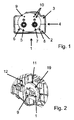
- a two-part pipe duct plate 1 is shown in a simplified plan view.
- the pipe lead-through plate 1 has an upper half 3 and a lower half 2.
- the two halves 2, 3 are connected together along a connecting line 4, wherein the two halves 2, 3 using clip connections 15 (cf. Fig. 3 ) are attached to each other.
- a tube pair 5, 7 is inserted between the two halves 2, 3 of the pipe lead-through plate 1, a tube pair 5, 7 is inserted.
- a tube 5, 7 is passed through a corresponding passage opening 6, 8.
- the two tubes 5, 7 open into a connecting flange 9.
- the ends of the two tubes 5, 7, which are preferably permanently connected to the connecting flange 9 and soldered in the present case to recognize.
- the connecting flange 9 the tubes can be connected to other components.
- To produce a mechanically strong connection with such other assemblies serve in the connecting flange 9 to be recognized holes 10, which may be provided with a thread, for example, or may be formed as a pure centering holes.
- the illustrated tubes 5, 7 and the connecting flange 9 are designed for use with R744.
- Fig. 2 is the in Fig. 1 illustrated pipe passage plate 1 again shown in a perspective view.
- the pipe penetration plate 1 is inserted into a corresponding recess 11 which is formed in the housing 12 of a motor vehicle air conditioning system.
- the pipe lead-through plate 1 is located in the recess 11 and is suitably secured to the housing.
- Fig. 3 is the in Fig. 2 shown arrangement shown in a schematic cross section seen from above.
- the section runs along the connecting line 4, so that the upper edge 14 of the lower half 2 of the pipe lead-through plate 1 can be seen.
- the tubes 5, 7, which may be, for example, the refrigerant supply of the evaporator, each extend through the passage opening corresponding thereto formed 6, 8.
- the ends of the tubes 5, 7, especially in the case of R744, are permanently soldered to the connecting flange 9.
- the clip connection 15 is preferably designed so that it can be loosened for maintenance purposes, for example.
- the pipe lead-through plate 1 is inserted in the recess 11 of the housing 12 of the motor vehicle air conditioning system.
- the pipe lead-through plate 1 is fastened in a suitable manner to the housing 12 of the motor vehicle air conditioning system. This can be done, for example, by a (perforated) lid 13 or as in Figure 3 represented by a tongue and groove connection with the housing 12. Additionally is in FIG. 3 to recognize the end wall 27, to which the housing 12 of the air conditioner is attached. For clarity, the end wall is only in FIG. 3 represented and shown only partially.
- a sealing strip 16 is provided between the upper 3 and the lower half 2 of the pipe duct plate 1. Furthermore, a sleeve-like executed annular seal 17 is provided in each case between a tube 5, 7 and the corresponding passage opening 6, 8.
- the ring seals 17 can not only serve the additional sealing, but can simultaneously cause a tolerance compensation. Also, with the help of the ring seals 17 optionally a noise caused by "rattling" can be avoided.
- Another seal is provided in the form of a sealing lip 18 between connecting flange 9 and end wall 27. Furthermore, an end wall seal 19, for example made of a sealing foam is provided between the Sfimwand 27 and the housing 12 of the motor vehicle air conditioning. Also between the outside of the pipe passage plate 1 and the recess 11 in the housing 12 of the automotive air conditioning system, a seal 20 is provided in the example shown.
- Fig. 4 is another embodiment of a pipe passage plate 21 can be seen in a perspective view.
- the pipe passage plate 21 is inserted into the corresponding recess 11, which is formed in the housing 12 of a motor vehicle air conditioning system.
- the outer dimensions of the housing 12 and in particular the recess 11 formed in the housing 12 are to that in the Fig. 2 shown housing or the recess 11 shown there identical.
- the pipe passage plate 21 consists of two interconnected items and is suitably connected to the housing 12 of the automotive air conditioning system.
- FIG. 4 shows motor vehicle air conditioning with R134a operated as a refrigerant. Instead of a connecting flange, therefore, a thermostatically controlled expansion valve 22 at the pipe ends 5, 7 are arranged.
- the pipe lead-through plate 21 can be carried out, inter alia, so that the expansion valve 22 is received to a large extent by the pipe lead-through plate 21.
- the Housing 12 and the components arranged therein have corresponding adjustments.
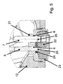
- Fig. 5 is the in Fig. 4 shown in perspective in a schematic cross-sectional view seen from above.
- the tubes 5, 7 extend through the passage openings 6, 8 corresponding thereto. In the region of the ends of the tubes 5, 7, these are provided with a peripheral projection 25, 26.
- the ends of the tubes 5, 7 themselves are inserted into corresponding connection openings of the expansion valve 22.
- the projections 25, 26 of the tubes 5, 7 are engaged behind by a counter-plate 24, so that the tubes 5, 7 are fixed in their position.
- FIG. 5 the arrangement of large parts of the expansion valve 22 in a trough-like recess 23 within the pipe passage plate 21 can be seen. Similar in connection with Fig. 3 described seals can also be provided in this case at different locations in order to increase the tightness of the arrangement.
Landscapes
- Engineering & Computer Science (AREA)
- General Engineering & Computer Science (AREA)
- Mechanical Engineering (AREA)
- Physics & Mathematics (AREA)
- Thermal Sciences (AREA)
- Air-Conditioning For Vehicles (AREA)
- Arrangement Or Mounting Of Propulsion Units For Vehicles (AREA)
- Valves And Accessory Devices For Braking Systems (AREA)
Applications Claiming Priority (1)
| Application Number | Priority Date | Filing Date | Title |
|---|---|---|---|
| DE102008005784A DE102008005784A1 (de) | 2008-01-23 | 2008-01-23 | Durchführungsvorrichtung |
Publications (2)
| Publication Number | Publication Date |
|---|---|
| EP2083202A2 true EP2083202A2 (fr) | 2009-07-29 |
| EP2083202A3 EP2083202A3 (fr) | 2010-10-06 |
Family
ID=40591853
Family Applications (1)
| Application Number | Title | Priority Date | Filing Date |
|---|---|---|---|
| EP08021608A Withdrawn EP2083202A3 (fr) | 2008-01-23 | 2008-12-12 | Dispositif de passage traversant |
Country Status (2)
| Country | Link |
|---|---|
| EP (1) | EP2083202A3 (fr) |
| DE (1) | DE102008005784A1 (fr) |
Cited By (3)
| Publication number | Priority date | Publication date | Assignee | Title |
|---|---|---|---|---|
| WO2020127652A1 (fr) * | 2018-12-20 | 2020-06-25 | Valeo Equipements Electriques Moteur | Ensemble comprenant une cloche d'embrayage et une machine electrique tournante pourvue d'une chambre de refroidissement |
| CN111845254A (zh) * | 2019-04-25 | 2020-10-30 | 马勒国际有限公司 | 用于引导流体的流体线路系统和用于机动车辆的空调设备 |
| CN112555548A (zh) * | 2020-12-18 | 2021-03-26 | 徐州徐工随车起重机有限公司 | 一种新型工程机械用中心回转接头 |
Citations (4)
| Publication number | Priority date | Publication date | Assignee | Title |
|---|---|---|---|---|
| DE10003254A1 (de) | 1999-02-04 | 2000-08-10 | Denso Corp | Fahrzeug-Klimaamlage mit problemlos montier- und demontierbarem Verdampfer |
| DE19949131A1 (de) | 1999-10-12 | 2001-04-19 | Behr Gmbh & Co | Abdichtanordnung für eine Leitungsdurchführung |
| DE10060105A1 (de) | 1999-12-06 | 2001-06-13 | Denso Corp | Cockpit-Modulaufbau mit Klimaanlage für ein Fahrzeug |
| DE102005039796A1 (de) | 2005-08-22 | 2007-03-08 | Behr Gmbh & Co. Kg | Verbindungsanordnung, insbesondere für CO2-Leitungen einer Kraftfahrzeug-Klimaanlage |
Family Cites Families (7)
| Publication number | Priority date | Publication date | Assignee | Title |
|---|---|---|---|---|
| DE1750240C3 (de) * | 1968-04-10 | 1975-02-20 | Vereinigte Flugtechnische Werkefokker Gmbh, 2800 Bremen | Wanddurchführung zur Befestigung von mehreren parallelen Rohren, elektrischen Kabeln od.dgl |
| US3634608A (en) * | 1970-07-31 | 1972-01-11 | Westinghouse Electric Corp | Strain relief bushing |
| US5234185A (en) * | 1992-02-21 | 1993-08-10 | General Motors Corporation | Unitary pipe clamp and assembly |
| US5806139A (en) * | 1996-04-24 | 1998-09-15 | Hi-Lex Corporation | Grommet assembly |
| AT7504U1 (de) * | 2004-02-13 | 2005-04-25 | Neuhofer Franz Jun | Abdeckung für eine durchführung zweier paralleler rohrleitungen, insbesondere für heizkörper |
| JP4166198B2 (ja) * | 2004-06-30 | 2008-10-15 | 東海ゴム工業株式会社 | パネル貫通の配管部材の固定装置 |
| US7464966B2 (en) * | 2004-06-30 | 2008-12-16 | Tokai Rubber Industries, Inc. | Through-panel fixing device for piping member |
-
2008
- 2008-01-23 DE DE102008005784A patent/DE102008005784A1/de not_active Withdrawn
- 2008-12-12 EP EP08021608A patent/EP2083202A3/fr not_active Withdrawn
Patent Citations (4)
| Publication number | Priority date | Publication date | Assignee | Title |
|---|---|---|---|---|
| DE10003254A1 (de) | 1999-02-04 | 2000-08-10 | Denso Corp | Fahrzeug-Klimaamlage mit problemlos montier- und demontierbarem Verdampfer |
| DE19949131A1 (de) | 1999-10-12 | 2001-04-19 | Behr Gmbh & Co | Abdichtanordnung für eine Leitungsdurchführung |
| DE10060105A1 (de) | 1999-12-06 | 2001-06-13 | Denso Corp | Cockpit-Modulaufbau mit Klimaanlage für ein Fahrzeug |
| DE102005039796A1 (de) | 2005-08-22 | 2007-03-08 | Behr Gmbh & Co. Kg | Verbindungsanordnung, insbesondere für CO2-Leitungen einer Kraftfahrzeug-Klimaanlage |
Cited By (8)
| Publication number | Priority date | Publication date | Assignee | Title |
|---|---|---|---|---|
| WO2020127652A1 (fr) * | 2018-12-20 | 2020-06-25 | Valeo Equipements Electriques Moteur | Ensemble comprenant une cloche d'embrayage et une machine electrique tournante pourvue d'une chambre de refroidissement |
| FR3091069A1 (fr) * | 2018-12-20 | 2020-06-26 | Valeo Equipements Electriques Moteur | Ensemble comprenant une machine électrique tournante pourvue d’une chambre de refroidissement et logée à l’intérieur d’une enceinte délimitée par une cloche d’embrayage |
| CN113196630A (zh) * | 2018-12-20 | 2021-07-30 | 法雷奥电机设备公司 | 包括离合器壳体和设有冷却室的旋转电机的组件 |
| JP2022515396A (ja) * | 2018-12-20 | 2022-02-18 | ヴァレオ エキプマン エレクトリク モトゥール | クラッチハウジングを備えるアセンブリ及び冷却チャンバーが設けられる回転電気機械 |
| JP7140921B2 (ja) | 2018-12-20 | 2022-09-21 | ヴァレオ エキプマン エレクトリク モトゥール | クラッチハウジングを備えるアセンブリ及び冷却チャンバーが設けられる回転電気機械 |
| CN111845254A (zh) * | 2019-04-25 | 2020-10-30 | 马勒国际有限公司 | 用于引导流体的流体线路系统和用于机动车辆的空调设备 |
| CN111845254B (zh) * | 2019-04-25 | 2023-12-15 | 马勒国际有限公司 | 用于引导流体的流体线路系统和用于机动车辆的空调设备 |
| CN112555548A (zh) * | 2020-12-18 | 2021-03-26 | 徐州徐工随车起重机有限公司 | 一种新型工程机械用中心回转接头 |
Also Published As
| Publication number | Publication date |
|---|---|
| EP2083202A3 (fr) | 2010-10-06 |
| DE102008005784A1 (de) | 2009-07-30 |
Similar Documents
| Publication | Publication Date | Title |
|---|---|---|
| DE2512566A1 (de) | Verschwenkbarer anschluss fuer fluide | |
| DE102009011951A1 (de) | Abgasklappenvorrichtung für Kraftfahrzeuge sowie Verfahren zur Montage einer Abgasklappenvorrichtung | |
| DE102009020060B4 (de) | Fahrzeugklimaanlagenbaugruppe und Verfahren zum Zusammenbau | |
| EP2019765A1 (fr) | Dispositif et procédé pour fixer un moteur d'essuie-glace sur une tringlerie d'essuie-glace | |
| EP2083202A2 (fr) | Dispositif de passage traversant | |
| DE202018101358U1 (de) | Einsatz zur Verbindung eines elektrischen Anschlusses mit einer Wand | |
| EP2334968B1 (fr) | Accouplement à verrouillage | |
| DE102006029645A1 (de) | Kältemittelleitung, insbesondere für mit CO2 betriebene Kraftfahrzeugklimaanlagen | |
| DE102015112519A1 (de) | Windschutzhülle und eine Steckverbindungsvorrichtung mit einer solchen | |
| DE102008005619A1 (de) | Schnellverschluss | |
| EP4244515B1 (fr) | Dispositif de raccordement pour un tuyau à nervures circonférentielles | |
| DE102009037304A1 (de) | Kraftfahrzeugklimaanlage | |
| DE102008059294A1 (de) | Beleuchtungseinrichtung für ein Kraftfahrzeug | |
| DE19703519C1 (de) | Klimagehäuse für eine Klimaanlage für Fahrzeuge | |
| DE102018106492A1 (de) | Klimaanlagengehäuse | |
| WO2011047843A1 (fr) | Dispositif de fixation pour une partie de garniture intérieure sur la carrosserie d'un véhicule à moteur | |
| DE102013212851A1 (de) | Verteilvorrichtung für die Verteilung von Kühlfluid in einem Kühlsystem einer Batterie | |
| EP2741905A1 (fr) | Fixation d'une pièce moulée par soufflage | |
| EP1719648B1 (fr) | Dispositif de fixation et d'étanchéité d'une valve de détente de climatisation automobile | |
| DE102011056319A1 (de) | Luftleitvorrichtung | |
| DE102018118234B4 (de) | Luftausströmer | |
| DE102016209931A1 (de) | Anordnung zum Sammeln und Abführen von ausgetretenem Kältemittel | |
| DE102007023160A1 (de) | Hydraulik- und/oder Pneumatikvorrichtung sowie Hydraulik- und/oder Pneumatiksystem | |
| DE102015217786A1 (de) | Vorrichtung zur Herstellung einer Axialverbindung, insbesondere in einem Kältemittelkreislauf eines Kraftfahrzeugs | |
| EP2910792A1 (fr) | Dispositif de liaison pour la liaison fluidique d'une section de tube de fluide avec une autre section de tube de fluide |
Legal Events
| Date | Code | Title | Description |
|---|---|---|---|
| PUAI | Public reference made under article 153(3) epc to a published international application that has entered the european phase |
Free format text: ORIGINAL CODE: 0009012 |
|
| AK | Designated contracting states |
Kind code of ref document: A2 Designated state(s): AT BE BG CH CY CZ DE DK EE ES FI FR GB GR HR HU IE IS IT LI LT LU LV MC MT NL NO PL PT RO SE SI SK TR |
|
| AX | Request for extension of the european patent |
Extension state: AL BA MK RS |
|
| PUAL | Search report despatched |
Free format text: ORIGINAL CODE: 0009013 |
|
| AK | Designated contracting states |
Kind code of ref document: A3 Designated state(s): AT BE BG CH CY CZ DE DK EE ES FI FR GB GR HR HU IE IS IT LI LT LU LV MC MT NL NO PL PT RO SE SI SK TR |
|
| AX | Request for extension of the european patent |
Extension state: AL BA MK RS |
|
| AKY | No designation fees paid | ||
| REG | Reference to a national code |
Ref country code: DE Ref legal event code: R108 Effective date: 20110526 |
|
| STAA | Information on the status of an ep patent application or granted ep patent |
Free format text: STATUS: THE APPLICATION IS DEEMED TO BE WITHDRAWN |
|
| 18D | Application deemed to be withdrawn |
Effective date: 20110407 |