EP2083226A2 - Klimaanlage und Steuerverfahren dafür mit Fernsteuerung zur Namenzuweisung für die Inneneinheiten - Google Patents
Klimaanlage und Steuerverfahren dafür mit Fernsteuerung zur Namenzuweisung für die Inneneinheiten Download PDFInfo
- Publication number
- EP2083226A2 EP2083226A2 EP08252063A EP08252063A EP2083226A2 EP 2083226 A2 EP2083226 A2 EP 2083226A2 EP 08252063 A EP08252063 A EP 08252063A EP 08252063 A EP08252063 A EP 08252063A EP 2083226 A2 EP2083226 A2 EP 2083226A2
- Authority
- EP
- European Patent Office
- Prior art keywords
- unit
- address
- indoor
- indoor unit
- address data
- Prior art date
- Legal status (The legal status is an assumption and is not a legal conclusion. Google has not performed a legal analysis and makes no representation as to the accuracy of the status listed.)
- Ceased
Links
Images



Classifications
-
- F—MECHANICAL ENGINEERING; LIGHTING; HEATING; WEAPONS; BLASTING
- F24—HEATING; RANGES; VENTILATING
- F24F—AIR-CONDITIONING; AIR-HUMIDIFICATION; VENTILATION; USE OF AIR CURRENTS FOR SCREENING
- F24F3/00—Air-conditioning systems in which conditioned primary air is supplied from one or more central stations to distributing units in the rooms or spaces where it may receive secondary treatment; Apparatus specially designed for such systems
- F24F3/06—Air-conditioning systems in which conditioned primary air is supplied from one or more central stations to distributing units in the rooms or spaces where it may receive secondary treatment; Apparatus specially designed for such systems characterised by the arrangements for the supply of heat-exchange fluid for the subsequent treatment of primary air in the room units
- F24F3/065—Air-conditioning systems in which conditioned primary air is supplied from one or more central stations to distributing units in the rooms or spaces where it may receive secondary treatment; Apparatus specially designed for such systems characterised by the arrangements for the supply of heat-exchange fluid for the subsequent treatment of primary air in the room units with a plurality of evaporators or condensers
-
- F—MECHANICAL ENGINEERING; LIGHTING; HEATING; WEAPONS; BLASTING
- F24—HEATING; RANGES; VENTILATING
- F24F—AIR-CONDITIONING; AIR-HUMIDIFICATION; VENTILATION; USE OF AIR CURRENTS FOR SCREENING
- F24F11/00—Control or safety arrangements
- F24F11/50—Control or safety arrangements characterised by user interfaces or communication
- F24F11/56—Remote control
-
- F—MECHANICAL ENGINEERING; LIGHTING; HEATING; WEAPONS; BLASTING
- F24—HEATING; RANGES; VENTILATING
- F24F—AIR-CONDITIONING; AIR-HUMIDIFICATION; VENTILATION; USE OF AIR CURRENTS FOR SCREENING
- F24F11/00—Control or safety arrangements
- F24F11/30—Control or safety arrangements for purposes related to the operation of the system, e.g. for safety or monitoring
-
- F—MECHANICAL ENGINEERING; LIGHTING; HEATING; WEAPONS; BLASTING
- F24—HEATING; RANGES; VENTILATING
- F24F—AIR-CONDITIONING; AIR-HUMIDIFICATION; VENTILATION; USE OF AIR CURRENTS FOR SCREENING
- F24F11/00—Control or safety arrangements
- F24F11/50—Control or safety arrangements characterised by user interfaces or communication
- F24F11/52—Indication arrangements, e.g. displays
-
- F—MECHANICAL ENGINEERING; LIGHTING; HEATING; WEAPONS; BLASTING
- F24—HEATING; RANGES; VENTILATING
- F24F—AIR-CONDITIONING; AIR-HUMIDIFICATION; VENTILATION; USE OF AIR CURRENTS FOR SCREENING
- F24F11/00—Control or safety arrangements
- F24F11/50—Control or safety arrangements characterised by user interfaces or communication
- F24F11/54—Control or safety arrangements characterised by user interfaces or communication using one central controller connected to several sub-controllers
-
- F—MECHANICAL ENGINEERING; LIGHTING; HEATING; WEAPONS; BLASTING
- F24—HEATING; RANGES; VENTILATING
- F24F—AIR-CONDITIONING; AIR-HUMIDIFICATION; VENTILATION; USE OF AIR CURRENTS FOR SCREENING
- F24F11/00—Control or safety arrangements
- F24F11/62—Control or safety arrangements characterised by the type of control or by internal processing, e.g. using fuzzy logic, adaptive control or estimation of values
-
- F—MECHANICAL ENGINEERING; LIGHTING; HEATING; WEAPONS; BLASTING
- F24—HEATING; RANGES; VENTILATING
- F24F—AIR-CONDITIONING; AIR-HUMIDIFICATION; VENTILATION; USE OF AIR CURRENTS FOR SCREENING
- F24F11/00—Control or safety arrangements
- F24F11/62—Control or safety arrangements characterised by the type of control or by internal processing, e.g. using fuzzy logic, adaptive control or estimation of values
- F24F11/63—Electronic processing
- F24F11/64—Electronic processing using pre-stored data
-
- F—MECHANICAL ENGINEERING; LIGHTING; HEATING; WEAPONS; BLASTING
- F25—REFRIGERATION OR COOLING; COMBINED HEATING AND REFRIGERATION SYSTEMS; HEAT PUMP SYSTEMS; MANUFACTURE OR STORAGE OF ICE; LIQUEFACTION SOLIDIFICATION OF GASES
- F25B—REFRIGERATION MACHINES, PLANTS OR SYSTEMS; COMBINED HEATING AND REFRIGERATION SYSTEMS; HEAT PUMP SYSTEMS
- F25B2313/00—Compression machines, plants or systems with reversible cycle not otherwise provided for
- F25B2313/023—Compression machines, plants or systems with reversible cycle not otherwise provided for using multiple indoor units
-
- F—MECHANICAL ENGINEERING; LIGHTING; HEATING; WEAPONS; BLASTING
- F25—REFRIGERATION OR COOLING; COMBINED HEATING AND REFRIGERATION SYSTEMS; HEAT PUMP SYSTEMS; MANUFACTURE OR STORAGE OF ICE; LIQUEFACTION SOLIDIFICATION OF GASES
- F25B—REFRIGERATION MACHINES, PLANTS OR SYSTEMS; COMBINED HEATING AND REFRIGERATION SYSTEMS; HEAT PUMP SYSTEMS
- F25B2313/00—Compression machines, plants or systems with reversible cycle not otherwise provided for
- F25B2313/025—Compression machines, plants or systems with reversible cycle not otherwise provided for using multiple outdoor units
Definitions
- the present invention relates to an air conditioner and an operating method for the same, and more particularly, to an air conditioner for automatically searching a plurality of indoor units to automatically set addresses and names based on address data received from the respective indoor units, and an operating method for the same.
- an air conditioner is provided to perform cooling, heating, and air purification and is installed to discharge chilled or hot air into indoor and to purify indoor air for the purpose of making more comfortable indoor environment to human beings.
- the air conditioner is operated by which an indoor unit having a heat exchanger and an outdoor unit having a compressor and a heat exchanger are separately controlled and an electric power to be supplied to the compressor and the heat exchanger is controlled.
- a plurality of indoor units can be connected to a single outdoor.
- the outdoor unit is driven corresponding to the number of driven indoor units to supply refrigerant to the indoor units based on required operating mode so that the air conditioner is operated in a cooling mode or a heating mode.
- the air conditioner further includes a remote controller for integrally controlling the plurality of indoor units and the outdoor unit from a remote place so that the indoor units and the outdoor unit are monitored and controlled.
- the remote controller assigns a centralized controlling address.
- the present invention provides an air conditioner, comprising: at least one outdoor unit (O); a plurality of indoor units (T) connected to the outdoor unit (O); and a remote controller (RC) for controlling the outdoor unit (O) and the indoor units (I), for sequentially requesting address data to the plural indoor units (I) to be connected, for assigning address information contained in the address data as centralized controlling addresses of the indoor units (I), and for automatically assigning and displaying names of the indoor units (I) based on the address information.
- a remote controller for controlling the outdoor unit (O) and the indoor units (I), for sequentially requesting address data to the plural indoor units (I) to be connected, for assigning address information contained in the address data as centralized controlling addresses of the indoor units (I), and for automatically assigning and displaying names of the indoor units (I) based on the address information.
- the present invention provides an operating method of an air conditioner, comprising: searching at least one connected indoor unit when an address assigning command is inputted to a remote controller (RC) for centralized-controlling an outdoor unit (O) and an indoor unit (I), and requesting address data to any one indoor unit (I) of the searched indoor units to receive the requested address data from the indoor unit (I); assigning address information contained in the address data as a centralized controlling address for the indoor unit (I) and automatically assigning a name of the indoor unit (I); and displaying the name of the indoor unit (I) on a screen and communicating with the indoor unit (T) using the centralized controlling address.
- RC remote controller
- the addresses are assigned based on the address data received from the plurality of indoor units by which the remote controller searches the indoor units and the names of the indoor units are automatically assigned. Therefore, it is not required to match actual indoor units with the list of the indoor units of the remote controller so that undesired efforts for that can be reduced. Since the remote controller easily distinguishes the respective indoor units, a user can conveniently use and the control and management of the plural indoor units are remarkably improved.
- FIG. 1 is a view showing the construction of an air conditioner in accordance with an embodiment of the present invention.
- the air conditioner according to the embodiment of the present invention includes a remote controller RC, an outdoor unit O, indoor units I (I1 to I4), and local controllers R (R1 to R4).
- At least one of the indoor units I is installed and includes an indoor heat-exchanger, an indoor fan, an expansion valve in which refrigerant supplied from the outdoor unit is expanded, and a plurality of temperature sensors.
- the outdoor unit O is connected to the indoor units I, and includes a compressor for receiving and compressing the refrigerant, an outdoor heat-exchanger for performing heat-exchange between the refrigerant and outdoor air, an accumulator for extracting gas refrigerant from the supplied refrigerant and for supplying the extracted gas refrigerant to the compressor, and a four-way valve for selecting a passage for the refrigerant corresponding to a heading operation.
- the outdoor unit O further includes a plurality of pressure sensors for measuring a pressure of the refrigerant discharged from the compressor, temperature sensors, a plurality of sensors, valves, and an oil recovery, but the description for the components will be omitted in the following description.
- the outdoor unit O and the indoor units I are connected through a refrigerant pipe to perform a cooling operation or a heating operation based on the flow of the refrigerant between the outdoor unit and the indoor units.
- the outdoor unit O and the indoor units I transmit and receive data in a preset communication method.
- the outdoor unit O is driven by any one demand of at least one of the plural indoor units, and the number of the outdoor units and the number of compressors installed in the outdoor units are changed when the cooling capacity is changed in response to the driven indoor units.
- the remote controller RC is connected to the indoor units I and the outdoor unit O and transmits and receives data in a preset communication method to monitor and control the indoor units I and the outdoor unit O.
- a plurality of remote controllers RC may be connected to the indoor units I and the outdoor unit O or may be connected to each other through Internet.
- the local controller R is connected to at least one of the indoor units I1 to I4, changes the operation mode of the indoor unit according to an input by a user, and receives and outputs the operation status of the corresponding indoor unit.
- Wire local controller connected to the indoor units may be used as the local controllers R, alternately wireless local controller may be used according to circumstances.
- the air conditioner may further include a ventilation device and an air purifier in addition to the indoor units and the outdoor unit, but the description will be omitted.
- a ventilation device and an air purifier in addition to the indoor units and the outdoor unit, but the description will be omitted.
- FIG. 2 is a block diagram showing a configuration of a remote controller of the air conditioner according to an embodiment of the present invention.
- the remote controller RC includes a control unit 30, a data unit 40, a communication unit 60, an input unit 10, an output unit 20, and an address assigning unit 50.
- the input unit 10 includes at least one button or a touch input unit or both of the button and the touch input unit according to circumstances.
- the input unit 10 applies a user's command inputted by manipulating the above-mentioned input unit to the control unit 30.
- the output unit 20 includes a display device for outputting texts and images, and outputs the user's command inputted through the input unit 10 to a screen corresponding to an operation corresponding to the inputted user's command. Moreover, the output unit 20 displays the operation status of the plural indoor unit I1 to I4 received through the communication unit 60, and displays a control menu and a schedule setting menu for controlling the indoor units I1 to I4 on the screen.
- the output unit 20 may further include a speaker for outputting an effective sound, an alarming sound, and vocal guide, and a lamp to be turned on and off in addition to the display device.
- the data unit 40 stores data inputted by the input unit 10, data received from the indoor units I1 to I4 and the outdoor unit O through the communication unit 60, control data for controlling a unit including an indoor unit and an outdoor unit, and setting data for controlling the outdoor unit and the indoor units. Moreover, the data unit 40 stores schedule data for the indoor units, the outdoor unit, and another unit to be set by the control unit 30 in response to the user's command of the input unit 10. The data unit 40 stores control unit address data in which address data of the respective indoor units match with the names of the indoor units.
- the communication unit 60 includes a plurality of communication modules for transmitting and receiving data in the wire and wireless communication lines, and transmits and receives the data from and to the outdoor unit O and the indoor units I1 to I4 in a desired communication line to apply the data to the control unit 30.
- the control unit 30 controls the data transmitted and received through the communication unit 60 and controls data to be inputted and outputted such that data inputted by the input unit 10 are outputted through the output unit 15.
- the control unit 30 creates a control command for controlling the indoor units and the outdoor unit in response to the user's command inputted from the input unit 10 and transmits the control command to the communication unit 60.
- control unit 30 sets a schedule for the operations of the respective indoor units and the outdoor unit and transmits the control command through the communication unit 60 such that the respective indoor units or the outdoor unit are driven according to the assigned schedule.
- control unit 30 controls that a plurality of schedules is set for the respective indoor units and the outdoor unit, the indoor units are driven according to the schedules, and a corresponding schedule is stored in the data unit 40.
- the control unit 30 searches a connected indoor unit I and controls the address assigning unit 50 such that an address is assigned. Particularly, when the air conditioner is initially driven, when the remote controller is initially driven, or when information for the connected indoor unit is not registered, the centralized controlling address for the communication with and the transmission of a control signal to the respective indoor units is assigned.
- the address assigning unit 50 in response to the control command from the control unit 30, searches a connected indoor unit I and assigns addresses to the respective indoor units based on the address data received from the plural indoor units I.
- the respective indoor units are assigned with addresses in advance and the addresses are stored as the address data, and the address assigning unit 50 assigns the centralized controlling address of a corresponding indoor unit according to the address data received from the indoor unit.
- the address assigning unit 50 calls control unit address data stored in the data unit 40, and compares the received address data with an address list of the control unit address data to automatically assigns a name matched to the address data as a name of the corresponding indoor unit.
- the address assigning unit 50 accesses all the indoor unit of which connection is detected in peer to peer to receive the address data from the respective indoor units and to assign addresses, and repeats the above operation to finish the assigning of addresses to the plural indoor units.
- the address assigning unit 50 sequentially accesses the plural indoor unit in peer to peer manner to assign the addresses, stops the assigning of addresses to the corresponding indoor unit when a certain indoor unit does not respond for a predetermined time, and tries to assign an address of a next indoor unit. After assigning an address of a final indoor unit, the address assigning unit 50 checks whether there is an indoor unit of which address is not assigned and tries to assign an address to the corresponding indoor unit again.
- the address assigning unit 50 determines that the corresponding indoor unit has an error when a specific indoor unit is not assigned with an address even after performing the assigning of addresses for a predetermined times, and displays the error or excludes the corresponding indoor unit from targets to be controlled by the remote controller RC.
- the address assigning unit 50 transmits an address data request signal to the indoor unit, assigns address information contained in the address data to be received from the indoor unit as a centralized controlling address of a corresponding indoor unit, and automatically assigns names of the respective indoor units based on the control unit address data.
- the address data received from the indoor unit include the address information assigned to the indoor unit, identification information of the indoor unit, and information for a kind of the unit.
- the remote controller RC accesses the first indoor unit I1 to request address data, then the first indoor unit I1 transmits the stored address data to the remote controller RC.
- the address assigning unit 50 assigns the address of the first indoor unit I1 as '01' according to the address information '01' contained in the received address data.
- the address assigning unit 50 searches the address '01' from the control unit address data and assigns the name assigned to the address '01' as the name of the first indoor unit I1 when there are matched data.
- the name of the indoor unit assigned to '01' is '3-20'
- the name of the first indoor unit I1 becomes '3-20'.
- the kind of the unit may be assigned. That is, the ventilation device is assigned with a 'ventilation 3-51'.
- the address assigning unit 50 may assign a default name or an arbitrary name. moreover, when the control unit address data is not in the data unit 40, the address assigning unit 50 may request the indoor unit I or the outdoor unit O.
- the address assigning unit 50 when the assigning of addresses is completed, transmits a signal for informing the completion of assigning addresses to the control unit 30, the control unit 30 controls the data unit 40 to store the address information assigned to the respective indoor units. After this, the control unit 30 communicated with the indoor units based on the assigned address information.
- the names of the indoor unit assigned as described above are outputted on a control screen of the output unit 20 as names assigned with a list of the indoor units based on a control command.
- FIG. 3 is a block diagram illustrating the structure of an indoor unit of an air conditioner according to an embodiment of the present invention.
- the indoor unit I includes an indoor unit control unit 120, an indoor unit communication unit 150, an indoor unit input unit 130, an indoor unit output unit 140, and an indoor unit data unit 110.
- the indoor unit communication unit 150 includes at least one communication module and transmits and receives data from and to the local controller R, the remote controller RC, and the outdoor unit O in a preset communication manner.
- the indoor unit input unit 130 includes at least one input device in which preset data are inputted by pressing or touching and applies a command inputted from a user to the indoor unit control unit 120.
- the indoor unit input unit 130 includes buttons, a switch, and a touch input device of a touch screen.
- the indoor unit output unit 140 outputs an operating mode, an operation setting, and an operation status of the indoor unit.
- the indoor unit output unit 140 includes a display device for outputting texts. and may further include images, a lamp to be turned on and off, and a speaker for outputting preset sound.
- the indoor unit data unit 110 stores control data for controlling the indoor unit and an address information unit 111 stores address information of the indoor unit communication unit 150 communicating with another unit.
- the address information unit 111 stores address data inputted from the indoor unit input unit 130 or the local controller R as well as an outdoor unit assigning address when an address is separately assigned from the outdoor unit.
- the indoor unit control unit 120 controls the address data to be transmitted to the remote controller RC through the indoor unit communication unit 150 when the remote controller RC requests the address data through the indoor unit communication unit 150. At this time, the indoor unit control unit 120 calls and transmits the stored address data from the address information unit 111, and calls and transmits the data in the connected local controller R when there is no data stored in the address information unit 111.
- the indoor unit control unit 120 determines the address stored in the address information unit 111 is assigned as the centralized controlling address, and controls the indoor unit communication unit 150 to perform the communication using the stored address for the communication with the remote controller RC.
- data of an address different from the stored address among the data received from the remote controller RC is discarded, and data of the same address is received such that a predetermined operation is performed.
- FIG. 4 is a block diagram illustrating a configuration of a local controller of an air conditioner according to an embodiment of the present invention.
- the local controller R includes a local control unit 220, a local controller communication unit 230, a local controller input unit 240, a local controller output unit 250, and a data storage 210.
- the local controller communication unit 230 is connected to the indoor unit according to a communication manner. In this case, when the local controller R is connected to a single indoor unit, data are transmitted to the corresponding indoor unit and data of the indoor unit are received. When the local controller R is connected to plural indoor units, data are received from any one of the indoor units and the data are transmitted to the plural indoor units.
- the local controller input unit 240 includes at least one button to be pressed or a touch input device in which a touch is inputted to input a user's command. In this case, the local controller input unit 240 is able to input data for operation a status of the connected indoor unit. The local controller input unit 240 can input address data for the connected indoor unit.
- the local control unit 220 transmits the input data to the indoor unit and stores the corresponding data in the data storage 210.
- the local controller control unit 220 transmits the data stored in the data storage 210.
- the local control unit 220 provides a menu for inputting the address data.
- the local controller output unit 250 includes a display device for displaying the menu for setting an operation mode of the indoor unit, and outputs an operating status of the indoor unit based on the data received from the indoor unit.
- the local controller output unit 250 may further include a lamp and a speaker.
- the data storage 210 stores the address data inputted by the local controller input unit 240 by a control command of the local control unit 220, and stores a screen structure data to be outputted through the local controller output unit 250 of the local controller input unit 240 and control data to be transmitted to the indoor unit.
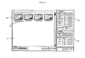
- FIG. 5 illustrates an example of a control screen of the remote controller in FIG. 3 .
- the remote controller RC displays an operation status of a connected device through the display device of the output unit 20, and provides a control menu such that a control setting for a corresponding device can be inputted.
- the remote controller RC displays an operation mode, an operation status, setting data, and information on current indoor status by icons 25 of indicating the indoor units using at least one of images, emoticons, texts together with a name 26 of the corresponding indoor unit.
- the name of the indoor unit is automatically assigned when the addresses of the respective indoor units are assigned.
- the remote controller RC analyses the address data received from the indoor unit to assign the address information contained in the address data as the centralized controlling address of a corresponding indoor unit, and searches the address information from the stored control unit address data to automatically a name assigned to corresponding address information as a name of the indoor unit and to display the same on the control screen when there is matched data.
- the address of the first indoor unit is assigned with '02' according to the address information contained in the address data, and a name such as '3-21' or 'an air conditioner 3-21' is automatically assigned to the corresponding indoor unit when the name assigned to '02' in the control unit address data is '3-21'.
- the displayed name may be changed by the user's input, and the name cannot be changed when a locking mode is set.
- the address data received from the indoor unit I are data inputted by the user by manipulating the indoor unit input unit 130 provided in the indoor unit I or the local controller input unit 240 provided in the local controller R.
- a control menu 22 for changing the setting of an operation mode, temperature, air volume of a selected indoor unit is displayed.
- a ventilation control menu 23 corresponding to the ventilation device may be further displayed.
- FIG. 6 is a front view illustrating the configuration of the local controller in FIG. 5 .
- buttons B01 to B38 is provided in the local controller input unit 240 of the local controller R and information on an indoor unit connected to the local controller output unit 250 is displayed.
- buttons B01 to B38 are function keys and moving keys for setting the operation of the indoor unit and are used as an input unit for inputting information on the indoor unit as occasion demands.
- the local controller R provides a menu through which a name and characteristics of the connected indoor unit are inputted, the data of the indoor unit are inputted by combination of the plural buttons.
- the data inputted by the button of the local controller are stored in the data storage 210 and are transmitted to the indoor unit I to be stored as data of assigning an address.
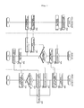
- FIG. 7 is a flowchart illustrating an address assigning method of an air conditioner according to the embodiment of the present invention.
- the local controller 220 stores the inputted data in the data storage 210 and transmits the data to the indoor unit I through the local controller communication unit 230 (S320).
- the indoor unit I stores the data received from the local controller R as the address data in the indoor unit data unit 110 (S350).
- the remote controller RC automatically searches a connected indoor unit I (S420). At this time, an address for the communication between the remote controller RC and the indoor unit I is not assigned, the connected indoor unit is searched and address data are received from the respective indoor units.
- the remote controller RC sequentially accesses the searched plural indoor units I and requests address data to the respective indoor unit I (S430).
- the remote controller RC sequentially accesses the respective indoor units in peer-to-peer manner.
- the order of the access may be an order of near communication line or searching but is not limited to this.
- the indoor unit I calls the stores address data and transmits the same to the remote controller RC.
- the indoor unit I determines whether there are stored address data (S370), and requests the address data to the local controller R when there is no data (S380).
- the local controller R calls the stored address data of the indoor unit in response to the request of the indoor unit I (S330) and transmits the same to the indoor unit (S340).
- the indoor unit I transmits the address data to the remote controller RC (S400).
- the remote controller RC analyses the address data and assigns the address information as the centralized controlling address of the corresponding indoor unit I. Moreover, the remote controller RC searches data matched to the address information from the control unit address data and automatically assigns the assigned name to the name of the corresponding indoor unit (S450).
- the remote controller assigns the address as the address of the corresponding indoor unit based on the address data, and searches data matched to '01' to assign the name '3-20' assigned to the data as the name of the first indoor unit 11.
- the first indoor unit I1 displays 'air conditioner 3-20'.
- the air conditioner indicates the kind of the first indoor unit I1 which can be changed according to the setting.
- the remote controller RC disconnects the access to the corresponding indoor unit after standby for a predetermined time, and accesses the next indoor unit to perform the assigning of an address and a name (S470).
- the data request and the assigning of the address are retried to the corresponding indoor unit, and the corresponding indoor unit is determined to be malfunctioned and is excluded from controlling objects when the response is not received after a predetermined times of the try.
- the remote controller RC When a new indoor unit is connected or the indoor unit excluded from the controlling object is searched again, the remote controller RC assigns an address and a name to the new indoor unit in the above-mentioned manner and adds the new indoor unit to the controlling object. Meanwhile, when there is no address data in the indoor unit, the remote controller RC may voluntarily assign an address and a name to the indoor unit.
- the remote controller RC stores the assigned address information and name (S480), and starts the communication with the indoor unit.
- the respective indoor units I communicate with the remote controller RC using the stored addresses (S410).
- the remote controller RC displays the list of the entire connected indoor unit on the control screen, and communicates with the respective indoor units using the assigned addresses such that the operation status is outputted and the operation of the indoor unit can be controlled. At this time, the automatically assigned names of the indoor units are displayed on the control screen of the remote controller RC.
Landscapes
- Engineering & Computer Science (AREA)
- Chemical & Material Sciences (AREA)
- Combustion & Propulsion (AREA)
- Mechanical Engineering (AREA)
- General Engineering & Computer Science (AREA)
- Human Computer Interaction (AREA)
- Physics & Mathematics (AREA)
- Fuzzy Systems (AREA)
- Mathematical Physics (AREA)
- Signal Processing (AREA)
- Air Conditioning Control Device (AREA)
- Selective Calling Equipment (AREA)
Applications Claiming Priority (1)
| Application Number | Priority Date | Filing Date | Title |
|---|---|---|---|
| KR1020080008654A KR101472019B1 (ko) | 2008-01-28 | 2008-01-28 | 공기조화기 및 그 동작방법 |
Publications (2)
| Publication Number | Publication Date |
|---|---|
| EP2083226A2 true EP2083226A2 (de) | 2009-07-29 |
| EP2083226A3 EP2083226A3 (de) | 2015-02-25 |
Family
ID=40622132
Family Applications (1)
| Application Number | Title | Priority Date | Filing Date |
|---|---|---|---|
| EP08252063.6A Ceased EP2083226A3 (de) | 2008-01-28 | 2008-06-16 | Klimaanlage und Steuerverfahren dafür mit Fernsteuerung zur Namenzuweisung für die Inneneinheiten |
Country Status (3)
| Country | Link |
|---|---|
| EP (1) | EP2083226A3 (de) |
| KR (1) | KR101472019B1 (de) |
| CN (1) | CN101498476B (de) |
Cited By (8)
| Publication number | Priority date | Publication date | Assignee | Title |
|---|---|---|---|---|
| WO2012099372A3 (en) * | 2011-01-21 | 2012-12-06 | Lg Electronics Inc. | Central control system and method for setting control point thereof |
| JP2017083076A (ja) * | 2015-10-28 | 2017-05-18 | ダイキン工業株式会社 | 空気調和機 |
| CN106766027A (zh) * | 2017-01-10 | 2017-05-31 | 珠海格力电器股份有限公司 | 一种空调的控制系统和控制方法 |
| EP3184920A1 (de) * | 2015-12-23 | 2017-06-28 | Lg Electronics Inc. | Eingangsvorrichtung und klimaanlage damit |
| JP2018021754A (ja) * | 2017-11-10 | 2018-02-08 | 三菱電機株式会社 | 冷熱装置の管理装置 |
| JP2023519091A (ja) * | 2020-02-05 | 2023-05-10 | ダイキン工業株式会社 | ヒートポンプシステム、表示装置、利用側ユニットおよび情報出力方法 |
| JP2023080506A (ja) * | 2021-11-30 | 2023-06-09 | 中野冷機株式会社 | 冷凍機器の運転制御項目の設定値変更方法 |
| WO2026062864A1 (ja) * | 2024-09-20 | 2026-03-26 | パナソニックIpマネジメント株式会社 | 室内機制御システム、室内機制御システムの制御方法、及び制御プログラム |
Families Citing this family (15)
| Publication number | Priority date | Publication date | Assignee | Title |
|---|---|---|---|---|
| CN102957757B (zh) * | 2011-08-23 | 2015-05-13 | 珠海格力电器股份有限公司 | 空调系统及其通信地址匹配方法和装置 |
| CN102889669B (zh) * | 2012-10-26 | 2015-01-21 | 四川长虹电器股份有限公司 | 空调地址设定的方法 |
| KR102143347B1 (ko) * | 2013-05-06 | 2020-08-11 | 엘지전자 주식회사 | 원격제어기 및 그를 포함하는 공기조화기 시스템 |
| KR102140067B1 (ko) * | 2013-05-08 | 2020-07-31 | 엘지전자 주식회사 | 공기조화기 및 그 동작방법 |
| CN103398450B (zh) * | 2013-07-11 | 2015-11-18 | 青岛海信日立空调系统有限公司 | 支持多移动终端远程控制中央空调的系统和方法 |
| CN103383128B (zh) * | 2013-07-11 | 2016-09-07 | 青岛海信日立空调系统有限公司 | 多联式中央空调的集中控制系统和控制方法 |
| KR102155558B1 (ko) * | 2014-02-04 | 2020-09-21 | 엘지전자 주식회사 | 공기조화기 및 그 제어방법 |
| CN105276725B (zh) * | 2014-07-23 | 2019-01-11 | 珠海格力电器股份有限公司 | 一种多联空调热水机组 |
| CN104456839B (zh) * | 2014-11-14 | 2017-07-07 | 上海盈达空调设备股份有限公司 | 多功能无线空调控制器及控制系统 |
| KR101655797B1 (ko) * | 2014-11-21 | 2016-09-08 | 엘지전자 주식회사 | 공기조화기 및 그 제어방법 |
| KR102527919B1 (ko) * | 2016-12-21 | 2023-05-03 | 삼성전자주식회사 | 냉난방 전환 장치, 그 제어 방법 및 공기 조화 시스템 |
| KR102000071B1 (ko) * | 2017-10-12 | 2019-07-15 | 엘지전자 주식회사 | 공기조화기 시스템 및 그 제어 방법 |
| CN110691147B (zh) * | 2018-07-05 | 2021-07-27 | 青岛海尔空调电子有限公司 | 多联式控制系统的地址竞争方法 |
| KR102039489B1 (ko) * | 2018-10-04 | 2019-11-01 | 엘지전자 주식회사 | 공기조화기 및 그 동작방법 |
| CN117213027A (zh) * | 2022-06-02 | 2023-12-12 | 青岛海尔空调电子有限公司 | 用于多联机空调器的控制方法及装置、系统、终端控制器 |
Family Cites Families (6)
| Publication number | Priority date | Publication date | Assignee | Title |
|---|---|---|---|---|
| JP3230494B2 (ja) * | 1998-09-03 | 2001-11-19 | ダイキン工業株式会社 | 空気調和機および空気調和機におけるアドレス設定方法 |
| KR100452349B1 (ko) * | 2001-10-15 | 2004-10-12 | 엘지전자 주식회사 | 공기조화 시스템 및 그 셋팅방법 |
| JP4183433B2 (ja) * | 2001-11-30 | 2008-11-19 | 三菱重工業株式会社 | 設置場所名伝送方式空調装置、空調装置アドレス設定方法及び空調装置アドレス設定プログラム |
| KR100851004B1 (ko) * | 2002-03-06 | 2008-08-12 | 엘지전자 주식회사 | 멀티 공기조화기 및 존 셋팅방법 |
| JP4458486B2 (ja) * | 2005-08-02 | 2010-04-28 | 日立アプライアンス株式会社 | 空調システム及び空調管理装置 |
| JP3979436B1 (ja) * | 2006-03-09 | 2007-09-19 | ダイキン工業株式会社 | 空気調和機および空気調和機におけるアドレス設定方法 |
-
2008
- 2008-01-28 KR KR1020080008654A patent/KR101472019B1/ko not_active Expired - Fee Related
- 2008-06-16 EP EP08252063.6A patent/EP2083226A3/de not_active Ceased
- 2008-06-20 CN CN2008101269768A patent/CN101498476B/zh not_active Expired - Fee Related
Non-Patent Citations (1)
| Title |
|---|
| None * |
Cited By (10)
| Publication number | Priority date | Publication date | Assignee | Title |
|---|---|---|---|---|
| WO2012099372A3 (en) * | 2011-01-21 | 2012-12-06 | Lg Electronics Inc. | Central control system and method for setting control point thereof |
| US9389600B2 (en) | 2011-01-21 | 2016-07-12 | Lg Electronics Inc. | Central control system and method for setting control point thereof |
| JP2017083076A (ja) * | 2015-10-28 | 2017-05-18 | ダイキン工業株式会社 | 空気調和機 |
| EP3184920A1 (de) * | 2015-12-23 | 2017-06-28 | Lg Electronics Inc. | Eingangsvorrichtung und klimaanlage damit |
| CN106766027A (zh) * | 2017-01-10 | 2017-05-31 | 珠海格力电器股份有限公司 | 一种空调的控制系统和控制方法 |
| CN106766027B (zh) * | 2017-01-10 | 2022-08-09 | 珠海格力电器股份有限公司 | 一种空调的控制系统和控制方法 |
| JP2018021754A (ja) * | 2017-11-10 | 2018-02-08 | 三菱電機株式会社 | 冷熱装置の管理装置 |
| JP2023519091A (ja) * | 2020-02-05 | 2023-05-10 | ダイキン工業株式会社 | ヒートポンプシステム、表示装置、利用側ユニットおよび情報出力方法 |
| JP2023080506A (ja) * | 2021-11-30 | 2023-06-09 | 中野冷機株式会社 | 冷凍機器の運転制御項目の設定値変更方法 |
| WO2026062864A1 (ja) * | 2024-09-20 | 2026-03-26 | パナソニックIpマネジメント株式会社 | 室内機制御システム、室内機制御システムの制御方法、及び制御プログラム |
Also Published As
| Publication number | Publication date |
|---|---|
| CN101498476B (zh) | 2011-08-17 |
| KR101472019B1 (ko) | 2014-12-15 |
| EP2083226A3 (de) | 2015-02-25 |
| KR20090082728A (ko) | 2009-07-31 |
| CN101498476A (zh) | 2009-08-05 |
Similar Documents
| Publication | Publication Date | Title |
|---|---|---|
| EP2083226A2 (de) | Klimaanlage und Steuerverfahren dafür mit Fernsteuerung zur Namenzuweisung für die Inneneinheiten | |
| KR101374777B1 (ko) | 공기조화기 및 그 동작방법 | |
| JP6253675B2 (ja) | 空調機試運転アプリケーション、及び空調機試運転システム | |
| EP2056032B1 (de) | Klimaanlage und Betriebsverfahren dafür | |
| US20100292864A1 (en) | Air conditioner and method of controlling the same | |
| KR20150022255A (ko) | 가전기기, 가전기기 시스템 및 그 제어방법 | |
| US9863658B2 (en) | Room management apparatus and method for assigning rooms based on air conditioner state and room temperature | |
| KR101921537B1 (ko) | 공기조화기 시스템 | |
| US9104188B2 (en) | Equipment controlling system and controlling method thereof | |
| JP2016196978A (ja) | 空気調和機の監視システム、モバイル端末及び空気調和機の情報収集アプリケーション | |
| KR20090082727A (ko) | 설비기기 제어시스템 및 그 비상제어방법 | |
| JP2000111128A (ja) | 空気調和機 | |
| KR102206461B1 (ko) | 공기조화기 시스템 및 그 동작방법 | |
| KR101535142B1 (ko) | 공기조화기 및 그 동작방법 | |
| KR20090043874A (ko) | 공기조화기 및 그 동작방법 | |
| JP2008057893A (ja) | 空気調和システム及び空気調和システムの制御装置 | |
| EP4075072A1 (de) | Klimaanlagensystem | |
| KR20140132887A (ko) | 공기조화기 및 그 동작방법 | |
| KR102205162B1 (ko) | 공기조화기 시스템 및 그 동작방법 | |
| US20210285676A1 (en) | Air-conditioning system | |
| KR20130035022A (ko) | 공기조화기 및 그 제어방법 | |
| KR20070034820A (ko) | 다실 공기조화시스템 및 그 운전모드 제어방법 | |
| KR101450541B1 (ko) | 공기조화기 및 그 동작방법 | |
| KR20110004153A (ko) | 공기조화기 및 그 제어방법 | |
| JP3984945B2 (ja) | 空気調和装置システム |
Legal Events
| Date | Code | Title | Description |
|---|---|---|---|
| PUAI | Public reference made under article 153(3) epc to a published international application that has entered the european phase |
Free format text: ORIGINAL CODE: 0009012 |
|
| AK | Designated contracting states |
Kind code of ref document: A2 Designated state(s): AT BE BG CH CY CZ DE DK EE ES FI FR GB GR HR HU IE IS IT LI LT LU LV MC MT NL NO PL PT RO SE SI SK TR |
|
| AX | Request for extension of the european patent |
Extension state: AL BA MK RS |
|
| PUAL | Search report despatched |
Free format text: ORIGINAL CODE: 0009013 |
|
| AK | Designated contracting states |
Kind code of ref document: A3 Designated state(s): AT BE BG CH CY CZ DE DK EE ES FI FR GB GR HR HU IE IS IT LI LT LU LV MC MT NL NO PL PT RO SE SI SK TR |
|
| AX | Request for extension of the european patent |
Extension state: AL BA MK RS |
|
| RIC1 | Information provided on ipc code assigned before grant |
Ipc: F24F 3/06 20060101ALI20150116BHEP Ipc: F24F 11/00 20060101AFI20150116BHEP |
|
| 17P | Request for examination filed |
Effective date: 20150825 |
|
| RBV | Designated contracting states (corrected) |
Designated state(s): AT BE BG CH CY CZ DE DK EE ES FI FR GB GR HR HU IE IS IT LI LT LU LV MC MT NL NO PL PT RO SE SI SK TR |
|
| AKX | Designation fees paid |
Designated state(s): AT BE BG CH CY CZ DE DK EE ES FI FR GB GR HR HU IE IS IT LI LT LU LV MC MT NL NO PL PT RO SE SI SK TR |
|
| AXX | Extension fees paid |
Extension state: MK Extension state: RS Extension state: AL Extension state: BA |
|
| 17Q | First examination report despatched |
Effective date: 20160926 |
|
| 18R | Application refused |
Effective date: 20180730 |