EP2083281A1 - Suiveur solaire - Google Patents
Suiveur solaire Download PDFInfo
- Publication number
- EP2083281A1 EP2083281A1 EP08101016A EP08101016A EP2083281A1 EP 2083281 A1 EP2083281 A1 EP 2083281A1 EP 08101016 A EP08101016 A EP 08101016A EP 08101016 A EP08101016 A EP 08101016A EP 2083281 A1 EP2083281 A1 EP 2083281A1
- Authority
- EP
- European Patent Office
- Prior art keywords
- cell array
- solar cell
- solar
- signal
- motor
- Prior art date
- Legal status (The legal status is an assumption and is not a legal conclusion. Google has not performed a legal analysis and makes no representation as to the accuracy of the status listed.)
- Withdrawn
Links
Images



Classifications
-
- G—PHYSICS
- G01—MEASURING; TESTING
- G01S—RADIO DIRECTION-FINDING; RADIO NAVIGATION; DETERMINING DISTANCE OR VELOCITY BY USE OF RADIO WAVES; LOCATING OR PRESENCE-DETECTING BY USE OF THE REFLECTION OR RERADIATION OF RADIO WAVES; ANALOGOUS ARRANGEMENTS USING OTHER WAVES
- G01S3/00—Direction-finders for determining the direction from which infrasonic, sonic, ultrasonic or electromagnetic waves, or particle emission, not having a directional significance, are being received
- G01S3/78—Direction-finders for determining the direction from which infrasonic, sonic, ultrasonic or electromagnetic waves, or particle emission, not having a directional significance, are being received using electromagnetic waves other than radio waves
- G01S3/782—Systems for determining direction or deviation from predetermined direction
- G01S3/785—Systems for determining direction or deviation from predetermined direction using adjustment of orientation of directivity characteristics of a detector or detector system to give a desired condition of signal derived from that detector or detector system
- G01S3/786—Systems for determining direction or deviation from predetermined direction using adjustment of orientation of directivity characteristics of a detector or detector system to give a desired condition of signal derived from that detector or detector system the desired condition being maintained automatically
- G01S3/7861—Solar tracking systems
-
- F—MECHANICAL ENGINEERING; LIGHTING; HEATING; WEAPONS; BLASTING
- F24—HEATING; RANGES; VENTILATING
- F24S—SOLAR HEAT COLLECTORS; SOLAR HEAT SYSTEMS
- F24S50/00—Arrangements for controlling solar heat collectors
- F24S50/20—Arrangements for controlling solar heat collectors for tracking
-
- G—PHYSICS
- G01—MEASURING; TESTING
- G01S—RADIO DIRECTION-FINDING; RADIO NAVIGATION; DETERMINING DISTANCE OR VELOCITY BY USE OF RADIO WAVES; LOCATING OR PRESENCE-DETECTING BY USE OF THE REFLECTION OR RERADIATION OF RADIO WAVES; ANALOGOUS ARRANGEMENTS USING OTHER WAVES
- G01S3/00—Direction-finders for determining the direction from which infrasonic, sonic, ultrasonic or electromagnetic waves, or particle emission, not having a directional significance, are being received
- G01S3/78—Direction-finders for determining the direction from which infrasonic, sonic, ultrasonic or electromagnetic waves, or particle emission, not having a directional significance, are being received using electromagnetic waves other than radio waves
- G01S3/781—Details
-
- G—PHYSICS
- G05—CONTROLLING; REGULATING
- G05D—SYSTEMS FOR CONTROLLING OR REGULATING NON-ELECTRIC VARIABLES
- G05D3/00—Control of position or direction
- G05D3/10—Control of position or direction without using feedback
- G05D3/105—Solar tracker
-
- H—ELECTRICITY
- H02—GENERATION; CONVERSION OR DISTRIBUTION OF ELECTRIC POWER
- H02S—GENERATION OF ELECTRIC POWER BY CONVERSION OF INFRARED RADIATION, VISIBLE LIGHT OR ULTRAVIOLET LIGHT, e.g. USING PHOTOVOLTAIC [PV] MODULES
- H02S20/00—Supporting structures for PV modules
- H02S20/30—Supporting structures being movable or adjustable, e.g. for angle adjustment
- H02S20/32—Supporting structures being movable or adjustable, e.g. for angle adjustment specially adapted for solar tracking
-
- Y—GENERAL TAGGING OF NEW TECHNOLOGICAL DEVELOPMENTS; GENERAL TAGGING OF CROSS-SECTIONAL TECHNOLOGIES SPANNING OVER SEVERAL SECTIONS OF THE IPC; TECHNICAL SUBJECTS COVERED BY FORMER USPC CROSS-REFERENCE ART COLLECTIONS [XRACs] AND DIGESTS
- Y02—TECHNOLOGIES OR APPLICATIONS FOR MITIGATION OR ADAPTATION AGAINST CLIMATE CHANGE
- Y02E—REDUCTION OF GREENHOUSE GAS [GHG] EMISSIONS, RELATED TO ENERGY GENERATION, TRANSMISSION OR DISTRIBUTION
- Y02E10/00—Energy generation through renewable energy sources
- Y02E10/40—Solar thermal energy, e.g. solar towers
- Y02E10/47—Mountings or tracking
-
- Y—GENERAL TAGGING OF NEW TECHNOLOGICAL DEVELOPMENTS; GENERAL TAGGING OF CROSS-SECTIONAL TECHNOLOGIES SPANNING OVER SEVERAL SECTIONS OF THE IPC; TECHNICAL SUBJECTS COVERED BY FORMER USPC CROSS-REFERENCE ART COLLECTIONS [XRACs] AND DIGESTS
- Y02—TECHNOLOGIES OR APPLICATIONS FOR MITIGATION OR ADAPTATION AGAINST CLIMATE CHANGE
- Y02E—REDUCTION OF GREENHOUSE GAS [GHG] EMISSIONS, RELATED TO ENERGY GENERATION, TRANSMISSION OR DISTRIBUTION
- Y02E10/00—Energy generation through renewable energy sources
- Y02E10/50—Photovoltaic [PV] energy
Definitions
- the present invention relates to a photovoltaic module and, more particularly, to a solar tracker for a photovoltaic module.
- a photovoltaic module includes a solar cell array mounted on a frame and a solar tracker for directing the solar cell array to the sun.
- the photoelectric efficiency of the solar cell array can be maximized.
- a typical solar tracker includes the follow properties. Firstly, it tracks the brightest object in the sky. Secondly, it includes detectors for detecting the position of the brightest object. Thirdly, its tolerance is 1 to 3 degrees. Fourthly, it includes an analog circuit.
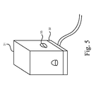
- a conventional solar tracker includes a shell 31, a circuit board 32 located in the shell 31 and four photo detectors 33 provided on the shell 31.
- the shell 31 includes four walls.
- Each of the photo detectors 33 is located on a related one of the walls of the shell 31.
- the photo detectors 33 are located at 45 degrees upward.
- the photo detectors 33 are directed to the east, the west, the south and the north, respectively.
- Each of the photo detectors 33 detects the brightness of the sunlit and provides a signal corresponding to the brightness. The intensities of the signals from the photo detectors 33 are calculated to determine the position of the sun.
- the tolerance is larger than 0.5 degrees.
- concentration photovoltaic modules are the most promising ones for high efficiencies.
- concentration photovoltaic modules those including III-V solar cells are the most popular ones.
- the tolerance must be smaller than 0.1 degrees.
- the circuit board 32 consumes much energy because it carries an analog circuit.
- the present invention is therefore intended to obviate or at least alleviate the problems encountered in prior art.
- the solar tracker includes a sunlit-detecting unit, a control unit, a first motor and a second motor.
- the sunlit-detecting unit detects the position of the sun.
- the control unit Based on the position of the sun, the control unit instructs the first motor to rotate a solar cell array and the second motor to tilt the solar cell array.
- the sunlit-detecting unit includes a base.
- a waterproof joint is inserted through the base.
- a circuit board is connected to the waterproof joint and formed with ten sockets.
- An integrated circuit includes ten pins inserted in the sockets and four photo diodes provided thereon for detecting sunlit and providing according signals.
- a plate is provided on the integrated board.
- a column is provided on the plate.
- a hat is mounted on the column.
- a transparent cover is provided on the base for covering the circuit board, the integrated circuit, the plate, the column and the hat.
- a photovoltaic module includes a solar cell array 15 and a solar tracker 1 according to the preferred embodiment of the present invention.
- the solar cell array 15 is provided on a beam supported on a post.
- the beam can be rotated about the post, i.e., about a vertical axis.
- the term “rotation” will be used to represent the angular motion about the vertical axis.
- the beam can be tilted on the post, i.e., pivoted about a horizontal axis.
- tilt will be used to represent the angular motion about the horizontal axis.
- the solar cell array 15 always intercepts the sunlit perpendicularly.
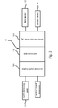
- the solar tracker 1 includes a sunlit-detecting unit 11, a control unit 12 connected to the sunlit-detecting unit 11, a first motor 13 connected to the control unit 12 and a second motor 14 connected to the control unit 12.
- the sunlit-detecting unit 11 detects the sunlit and sends signals to the control unit 12.
- the control unit 12 determines the position of the sun. According to the position of the sun, the control unit 12 makes the first motor 13 rotate the solar cell array 15. However, the operation of the first motor 13 will be stopped if the solar cell array 15 is in the eastern or western dead zone.
- the control unit 12 makes the second motor 14 tilt the solar cell array 15. However, the operation of the second motor 14 is stopped if the solar cell array 15 is in the southern or northern dead zone.
- the sunlit-detecting unit 11 includes a base 116, a circuit board 117 provided on the base 116, an integrated circuit ("IC") 111 provided on the circuit board 117, a column set 113 provided on the IC 111, a hat 114 mounted on the column set 113 and a transparent cover 115 provided on the base 116 for covering the circuit board 117, the IC 111, the column set 113 and the hat 114 and for allowing the sunlit to reach the IC 111.
- IC integrated circuit
- the base 116 is made of aluminum alloy.
- a waterproof joint 1161 is disposed in an aperture defined in the base 116.
- a wire 119 is provided between the waterproof joint 1161 and the control unit 2.
- the circuit board 117 is connected to the waterproof joint 1161.
- the circuit board 117 includes ten sockets 118 provided thereon.
- the IC 111 includes five pins 1111 extended from an edge, five pins 1111 extended from an opposite edge and five photo diodes 112 provided on the top.
- the pins 1111 are inserted in the sockets 118.
- the photo diodes 112 include a central diode 112, an eastern diode 112, a western diode 112, a southern diode 112 and a northern diode 112. Each of the diodes 112 is connected to two related ones of the pins 1111.
- the column set 113 includes a column 1131 supported on a plate 1132.
- the plate 1132 includes four apertures 1133 defined therein.
- the plate 1132 is provided on the IC 112 so that the apertures 1133 are aligned to the photo diodes 112.
- the ratio of the diameter of the apertures 1133 to the height of the column 1131 is lower than 1.
- the ratio of the diameter of the apertures 1133 to the thickness of the plate 1132 is higher than 1.
- the hat 114 includes a space 1141 defined in the bottom for receiving the column 1131.
- the ratio of the thickness of the hat 114 to the diameter of the apertures 1133 is lower than 1.
- the transparent cover 115 is in hemi-spherical.
- the control unit 12 includes an analog signal processor 121, a microprocessor 122 and a direct circuit ("DC") motor-driving circuit 123.
- the analog signal processor 121 is connected to the circuit board 117.
- the analog signal processor 121 amplifies the signals, filters noises from the signals, matches the impedances and adjusts the gains of the signals.
- the analog signal processor 121 may be a differential amplifier.
- the microprocessor 122 controls the operation of the solar tracker so that the solar cell array 15 always intercepts the sunlit perpendicularly.
- the DC motor-driving circuit 123 is connected to the first motor 13 so that the former can energize the latter to rotate in opposite directions.
- the DC motor-driving circuit 123 is connected to the second motor 14 so that the former can energize the latter to rotate in opposite directions.
- FIG. 3 and 4 there is shown a process executed by the solar tracker 1.
- the analog signal processor 121 of the control unit 12 processes the signals from the east, west, southern, and northern photo diodes 112.
- the differential between the signals from the eastern and western photo diodes 112 is calculated.
- the intensity of the signal from the west photo diode 112 is subtracted from the intensity of the signal from the east photo diode 112.
- the hat 114 will cast shadow on the west photo diode 112.
- the intensity of the signal from the east photo diode 112 will be higher than the intensity of the signal from the west photo diode 112.
- the east-west signal differential will be positive. In this case, the process goes to 212.
- the hat 114 will cast shadow on the east photo diode 112.
- the intensity of the signal from the east photo diode 112 will be lower than the intensity of the signal from the west photo diode 112.
- the east-west signal differential will be negative. In this case, the process goes to 213.
- the solar cell array 15 is in the eastern dead zone by comparing the east-west signal differential with a value corresponding to the eastern dead zone. If the solar cell array 15 is not in the eastern dead zone, a first signal will be provided.
- the solar cell array 15 is in the western dead zone by comparing the east-west signal differential with a value corresponding to the western dead zone. If the solar cell array 15 is not in the western dead zone, a second signal will be provided.
- the process will go back to 211 after providing the first or second signal.
- the differential between the signals from the southern and northern photo diodes 112 is calculated.
- the intensity of the signal from the north photo diode 112 is subtracted from the intensity of the signal from the south photo diode 112.
- the south photo diode 112 will be exposed to the sunlit and the hat 114 will cast shadow on the north photo diode 112.
- the intensity of the signal from the south photo diode 112 will be higher than the intensity of the signal from the north photo diode 112.
- the south-north signal differential will be positive. In this case, the process goes to 215.
- the north photo diode 112 will be exposed to the sunlit and the hat 114 will cast shadow on the south photo diode 112.
- the intensity of the signal from the south photo diode 112 will be lower than the intensity of the signal from the north photo diode 112.
- the south-north signal differential will be negative. In this case, the process goes to 216.
- the solar cell array 15 it is determined if the solar cell array 15 is in the northern dead zone by comparing the south-north signal differential with a value corresponding to the northern dead zone. If the solar cell array 15 is not in the northern dead zone, a fourth signal will be provided.
- the process will go back to 214 after providing the third or fourth signal.
- the solar tracker 1 At 22, it is determined if the brightness of the sunlit is larger than a predetermined value. If so, the solar tracker 1 will operate to direct the solar cell array 15 to the sun. Otherwise, the solar tracker 1 will stop.
- the control unit 12 instructs the first motor 13 to rotate the solar array 15 towards the east.
- the first motor 13 will be stopped if the solar array 15 is in the eastern dead zone.
- the control unit 12 instructs the first motor 13 to rotate the solar cell array 15 towards the west.
- the first motor 13 will be stopped if the solar array 15 is in the western dead zone.
- the control unit 12 instructs the second motor 14 to tilt the solar cell array 15 towards the south.
- the second motor 14 will be stopped if the solar array 15 is in the southern dead zone.
- the control unit 12 instructs the second motor 14 to tilt the solar array 15 towards the north.
- the second motor 14 will be stopped if the solar array 15 is in the northern dead zone.
- the east-west view angle of the solar tracker 1 is 180 degrees.
- the process must be reinitiated so that the solar tracker 1 directs the solar cell array 15 back to the east and north.
- the process must be reinitiated so that the solar tracker 1 directs the solar cell array 15 back to the east and north.
- the solar cell array 15 is directed to the sun.
- the solar tracker 1 is precise, inexpensive and reliable and consumes a little energy.
Landscapes
- Physics & Mathematics (AREA)
- Engineering & Computer Science (AREA)
- Life Sciences & Earth Sciences (AREA)
- Sustainable Development (AREA)
- General Physics & Mathematics (AREA)
- Remote Sensing (AREA)
- Electromagnetism (AREA)
- Radar, Positioning & Navigation (AREA)
- Automation & Control Theory (AREA)
- Sustainable Energy (AREA)
- Thermal Sciences (AREA)
- Chemical & Material Sciences (AREA)
- Combustion & Propulsion (AREA)
- Mechanical Engineering (AREA)
- General Engineering & Computer Science (AREA)
- Photovoltaic Devices (AREA)
Priority Applications (1)
| Application Number | Priority Date | Filing Date | Title |
|---|---|---|---|
| EP08101016A EP2083281A1 (fr) | 2008-01-28 | 2008-01-28 | Suiveur solaire |
Applications Claiming Priority (1)
| Application Number | Priority Date | Filing Date | Title |
|---|---|---|---|
| EP08101016A EP2083281A1 (fr) | 2008-01-28 | 2008-01-28 | Suiveur solaire |
Publications (1)
| Publication Number | Publication Date |
|---|---|
| EP2083281A1 true EP2083281A1 (fr) | 2009-07-29 |
Family
ID=39427700
Family Applications (1)
| Application Number | Title | Priority Date | Filing Date |
|---|---|---|---|
| EP08101016A Withdrawn EP2083281A1 (fr) | 2008-01-28 | 2008-01-28 | Suiveur solaire |
Country Status (1)
| Country | Link |
|---|---|
| EP (1) | EP2083281A1 (fr) |
Cited By (1)
| Publication number | Priority date | Publication date | Assignee | Title |
|---|---|---|---|---|
| EP2557431A1 (fr) * | 2011-08-09 | 2013-02-13 | General Electric Company | Système de suivi de panneau solaire et capteur de suivi associé |
Citations (4)
| Publication number | Priority date | Publication date | Assignee | Title |
|---|---|---|---|---|
| US3996917A (en) | 1974-03-27 | 1976-12-14 | Malz Nominees Pty. Ltd. | Solar heating apparatus |
| US5317145A (en) | 1991-12-31 | 1994-05-31 | Wattsun Corporation | Radiation source detector and tracker control having a shade pole and radiation responsive surface in the shape of narrow bands |
| US20040094691A1 (en) * | 2002-11-14 | 2004-05-20 | Redler Michael H. | Autonomous light tracking device and control circuitry |
| US20050041431A1 (en) * | 2003-08-21 | 2005-02-24 | Yaoming Zhang | Directed reflection light collecting device with planar reflectors |
-
2008
- 2008-01-28 EP EP08101016A patent/EP2083281A1/fr not_active Withdrawn
Patent Citations (4)
| Publication number | Priority date | Publication date | Assignee | Title |
|---|---|---|---|---|
| US3996917A (en) | 1974-03-27 | 1976-12-14 | Malz Nominees Pty. Ltd. | Solar heating apparatus |
| US5317145A (en) | 1991-12-31 | 1994-05-31 | Wattsun Corporation | Radiation source detector and tracker control having a shade pole and radiation responsive surface in the shape of narrow bands |
| US20040094691A1 (en) * | 2002-11-14 | 2004-05-20 | Redler Michael H. | Autonomous light tracking device and control circuitry |
| US20050041431A1 (en) * | 2003-08-21 | 2005-02-24 | Yaoming Zhang | Directed reflection light collecting device with planar reflectors |
Cited By (1)
| Publication number | Priority date | Publication date | Assignee | Title |
|---|---|---|---|---|
| EP2557431A1 (fr) * | 2011-08-09 | 2013-02-13 | General Electric Company | Système de suivi de panneau solaire et capteur de suivi associé |
Similar Documents
| Publication | Publication Date | Title |
|---|---|---|
| US7910870B2 (en) | Solar tracker | |
| US8247753B2 (en) | Solar tracking device and method for high-effective concentration photovoltaic | |
| US8324547B2 (en) | Solar tracking and concentration device | |
| US4367403A (en) | Array positioning system with out-of-focus solar cells | |
| CN104035449B (zh) | 一种太阳能电池板的双轴跟踪系统及其跟踪方法 | |
| US7507941B2 (en) | Hybrid mode sun-tracking apparatus having photo sensor | |
| KR101094730B1 (ko) | 3차원 반사거울형 채광장치의 태양광 자동추적 시스템 | |
| KR100970961B1 (ko) | 태양발전기용 태양광 추적 구동센서 | |
| RU2286517C1 (ru) | Солнечная фотоэлектрическая установка | |
| WO2017187445A1 (fr) | Détecteur de position du soleil et procédé de détection de position du soleil | |
| CN107317546A (zh) | 太阳能发电装置 | |
| KR20170034978A (ko) | 태양광 발전 장치 | |
| KR20140017048A (ko) | 4분할방식을 갖는 고정밀 태양광 추적센서 | |
| KR100727283B1 (ko) | 태양광 감지기 및 이를 이용한 태양광 집광 장치 및 방법 | |
| CN102566601B (zh) | 一种太阳跟踪传感器 | |
| CN205545108U (zh) | 一种自动阳光光线跟踪的太阳能发电设备 | |
| TWI300465B (fr) | ||
| JP4253194B2 (ja) | 集光式太陽光発電装置の太陽電池パネルの設置方法 | |
| US20110017270A1 (en) | Solar tracking device for solar cells | |
| KR20090098591A (ko) | 태양광 감지기 제어 모듈 | |
| CN220380493U (zh) | 一种用于太阳位置检测的类球体式光电传感器 | |
| JP3128040U (ja) | 光源追尾装置 | |
| CN1987291B (zh) | 智能太阳跟踪仪 | |
| JP4829866B2 (ja) | ヘリオスタットの太陽位置センサー機構とコントローラー及びその追随制御方法 | |
| JP2007101501A (ja) | 日照検出装置及び該日照検出装置を用いた電動ブラインドの制御装置 |
Legal Events
| Date | Code | Title | Description |
|---|---|---|---|
| PUAI | Public reference made under article 153(3) epc to a published international application that has entered the european phase |
Free format text: ORIGINAL CODE: 0009012 |
|
| 17P | Request for examination filed |
Effective date: 20080228 |
|
| AK | Designated contracting states |
Kind code of ref document: A1 Designated state(s): AT BE BG CH CY CZ DE DK EE ES FI FR GB GR HR HU IE IS IT LI LT LU LV MC MT NL NO PL PT RO SE SI SK TR |
|
| AX | Request for extension of the european patent |
Extension state: AL BA MK RS |
|
| 17Q | First examination report despatched |
Effective date: 20100219 |
|
| AKX | Designation fees paid |
Designated state(s): AT BE BG CH CY CZ DE DK EE ES FI FR GB GR HR HU IE IS IT LI LT LU LV MC MT NL NO PL PT RO SE SI SK TR |
|
| STAA | Information on the status of an ep patent application or granted ep patent |
Free format text: STATUS: THE APPLICATION IS DEEMED TO BE WITHDRAWN |
|
| 18D | Application deemed to be withdrawn |
Effective date: 20140801 |