EP2083485A2 - Connecteur électrique - Google Patents
Connecteur électrique Download PDFInfo
- Publication number
- EP2083485A2 EP2083485A2 EP09000809A EP09000809A EP2083485A2 EP 2083485 A2 EP2083485 A2 EP 2083485A2 EP 09000809 A EP09000809 A EP 09000809A EP 09000809 A EP09000809 A EP 09000809A EP 2083485 A2 EP2083485 A2 EP 2083485A2
- Authority
- EP
- European Patent Office
- Prior art keywords
- plug
- connector
- housing
- housings
- contact
- Prior art date
- Legal status (The legal status is an assumption and is not a legal conclusion. Google has not performed a legal analysis and makes no representation as to the accuracy of the status listed.)
- Granted
Links
Images

Classifications
-
- H—ELECTRICITY
- H01—ELECTRIC ELEMENTS
- H01R—ELECTRICALLY-CONDUCTIVE CONNECTIONS; STRUCTURAL ASSOCIATIONS OF A PLURALITY OF MUTUALLY-INSULATED ELECTRICAL CONNECTING ELEMENTS; COUPLING DEVICES; CURRENT COLLECTORS
- H01R13/00—Details of coupling devices of the kinds covered by groups H01R12/70 or H01R24/00 - H01R33/00
- H01R13/46—Bases; Cases
- H01R13/514—Bases; Cases composed as a modular blocks or assembly, i.e. composed of co-operating parts provided with contact members or holding contact members between them
Definitions
- the invention relates to a plug-in connector.
- Plug-in connectors of this type are used, for example, for attaching cables to devices in electrical appliances, machines, motors, vehicles or the like.
- a plug-in connector of this type is known, for example, from DE 20 2005 000 883 U1 .
- the object of the invention is to provide a plug-in connector which can be used for different plug-in contacts and simplifies the process of connection and attachment of a cable to a device.
- the invention provides the plug-in connector according to claim 1, including: a pair of plugs housings with two connectable plug housings and a pair of contact housings with two connectable contact housings, each plug housing comprising at least one socket for a contact housing.
- each contact housing can have a size which is adapted to the plug housing socket and/or standardised so contact housings equipped with different plug-in contacts can be inserted into the same plug housing.
- the same plug-in connector can therefore be used for different plug-in contacts.
- the contact housings can be connected to cable-side and device-side terminals outside the plug housing to simplify the connection process and the attachment of a cable to a device.
- the plug-in connector is configured in such a way that the contact housings are brought into contact on connection of the plug housings.
- the connection process and the attachment of the cable which is to be attached via the plug connector to the device can be further simplified in this way.
- the plug housing is lockable with a locking device.
- the locking device can prevent the plug housings from coming apart even under the influence of forces of abrasions.
- At least one of the plug housings is divisible, so that a contact housing can be arranged in the socket.
- a contact housing can therefore be arranged in the socket in a particularly simple and secure manner, thus simplifying assembly of the contact housings in the plug housing.
- each plug housing comprises at least one socket which is shielded from electromagnetic radiation.
- the influence of electromagnetic radiation from the environment can cause interference, in particular during signal transmission, and this represents a considerable safety risk, especially in automotive applications or in the aerospace sector.
- the entire plug housing is shielded from electromagnetic radiation.
- a socket of a plug housing is also shielded from electromagnetic radiation of which the origin is located in a different socket.
- a socket of a plug housing and/or the plug housing itself is lined and/or clad with a material, preferably metal, which acts as a shield against electromagnetic radiation, or is constructed completely from this material.
- each plug housing comprises at least one further socket for a further contact housing. Power and signals can therefore be transmitted, for example, simultaneously via the plug-in connection.
- sockets of a plug housing are adjacent transversely to a connection direction of the plug housings.
- the plug in connection can therefore have any number of sockets for contact housings.
- a plug housing and/or a contact housing has a polygonal, preferably substantially rectangular, more preferably substantially square cross-section.
- a plurality of plug housings and/or contact housings can therefore be arranged particularly densely next to one another.
- a cross-section of a contact housing is adapted substantially to a cross-section of a socket.
- the contact housing therefore has little play in the socket for movement within the socket, for example during vibrations. The reliability of the plug-in connection can thus be improved.
- a contact housing can be fixed non-positively and/or positively in a socket.
- the contact housing can therefore be held securely and rigidly in the socket and has no play for movement within the socket, for example during vibrations. The reliability of the plug-in connection can therefore be further improved.
- the plug-in connector can be fixed rotatably on a flange.
- the direction in which a cable which is to be attached to a device can be guided away from the device, can therefore be adjusted as desired.
- plug-in connector can be fixed or locked in a rotational position relative to the flange.
- the plug-in connection can thus be prevented from rotating unintentionally.
- the plug-in connector is configured as an angle plug-in connector.
- a cable which is to be attached to a device can thus be led away from the device with slight spacing, and this has proven to be particularly practical, in particular in a restricted space.
- connection direction of the plug housing is oriented along, parallel to or transversely to an axis of rotation of the plug-in connector.
- transverse as used in this description also includes the meanings of the terms “oblique”, “angled” and, in particular, “perpendicular”.
- one contact housing is configured as a plug pin and one contact housing as a plug socket.
- the contact housings can therefore engage in one another and be permanently connected.
- a further preferred embodiment of the invention relates to plug-in connector including a pair of plug housings with two connectable plug housings and a pair of plug-in contacts with two connectable plug-in contacts, the plug-in connector comprising a locking device for locking the plug housing and the plug-in contacts being brought into contact when the plug housings are locked.
- the plug housings can therefore be connected with a hand grip and at the same time locked.
- the locking device is mounted movably on a plug housing. A movement of the locking device relative to the plug housing can therefore be coupled to prevent faulty assembly of the plug-in connector.
- the locking device may be held captive on a plug housing.
- the risk of losing the locking device, for example during transportation, can also be reduced in this way.
- the locking device is movable transversely to a connection direction of the plug housings, for locking the plug housings.
- the locking device is movable in a plane of a housing division for locking the plug housings. This can prevent the locking device from being inadvertently released when a force acts transversely to the plane of the housing division.
- the locking device is configured as a substantially U-shaped hoop, surrounding the plug housing at least in some regions when locked.
- the plug housings can therefore be held together in an interlocking secure manner.
- a movement of the locking device relative to at least one of the plug housings is guided by a guide device. This enables the locking device to be operated easily, even by inexperienced personnel.
- a movement of the locking device relative to the first plug housing can be guided via a first link guide and a movement of the locking device relative to the second plug housing by a second link guide.
- the plug housings are thus guided particularly reliably and precisely relative to one another, and the risk of a defective connection or the risk of damage to plug contacts by defective connection is reduced.
- At least one guide link is constructed on the side of the locking device.
- the guide link can be constructed particularly easily in the locking device.
- a further preferred embodiment of the invention relates to a plug-in connector system including a plug-in connector according to any one of the preceding claims and at least two pairs of contact housings with two respective connectable contact housings, the pairs of contact housings being equipped with different pairs of plug-in contacts.
- the same plug-in connector can therefore be combined with different pairs of contact housings or pairs of plug-in contacts and is thus substantially more versatile than a conventional plug-in connector.
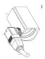
- Fig. 1 is a perspective view of a first embodiment of the plug-in connector according to the invention for attaching a multi-wire cable for transmitting power and signals to a motor, in the connected state.
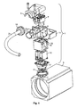
- Fig. 2 is an exploded view of the plug-in connector according to the invention from Fig. 1 .
- Fig. 3 is a perspective view of a second embodiment of the plug-in connector according to the invention for attaching a multi-wire cable for transmitting power and signals to a motor, in the connected state.
- Fig. 4 is an exploded view of the plug-in connector according to the invention from Fig. 3 .
- Fig. 5 is a perspective view of a third embodiment of the plug-in connector according to the invention for attaching a multi-wire cable for the transmitting of power and signals to a motor, in the connected state.
- a first feature of the invention relates to a plug-in connector 1 including a pair of plug housings 5, 8 with two connectable plug housings 5, 8 and a pair of contact housings 7, 10, with two connectable contact housings 7, 10, each plug housing 5, 8 comprising at least one socket 6, 9 for a contact housing 7, 10.
- the plug-in connector 1 is constructed in such a way that the contact housings 7, 10 are brought into contact when the plug housings 5, 8 are connected.
- Each plug housing 5,8 is produced with a polygonal, in particular substantially rectangular, cross-section, preferably from metal and/or plastics material, and comprises two sockets 6, 9 each with a polygonal, in particular substantially rectangular, cross-section.
- Each socket 6, 9 is adapted to receive a respective contact housing 7, 10.
- One socket 6, 9 of each plug housing 5, 8 is shielded from electromagnetic radiation.
- the sockets 6, 9 of a plug housing 5, 8 are arranged adjacent to one another transversely to a connection direction of the plug housings 5, 8.
- the socket 6, 9 which is shielded from electromagnetic radiation is intended for a contact housing 7, 10 for signal transmission and the other socket 6, 9 is intended for a contact housing 7, 10 for power transmission.
- Each plug housing 5, 8 is divisible so that the contact housings 7, 10 can be arranged in the sockets 6, 9.
- One contact housing 7 of a contact housing pair 7, 10 is configured as a plug pin and the other contact housing 10 of a contact housing pair 7, 10 as a plug socket.
- Each contact housing 7, 10 is preferably configured as an injection-moulded plastics component with a polygonal, in particular substantially rectangular cross-section, the cross-section of the contact housing 7, 10 being adapted substantially to the cross-section of an associated socket 6, 9 so the contact housing 7, 10 can be fixed non-positively in the associated socket 6, 9.
- the contact housing 7, 10 can be fixed positively in the socket intended for it, and can also be, for example, latched or screwed.
- Each contact housing 7, 10 is equipped with a plug-in contact, an associated pair of contact housings 7, 10 receiving an associated pair of plug-in contacts which is connected when the contact housing pair 7, 10 is connected.
- the contact housing pairs 7, 10 are selected, for example, from the applicant's HVS (high variable system) modular system.
- the plug-in connector 1 can be attached to a cable 2 via a cable-side terminal 16 with a cable grip and can be fixed rotatably on a flange 4 via a device-side terminal 17.
- the plug-in connector 1 can be fixed relative to the flange 4 via a union nut in a desired rotational position.
- a connection direction of the plug housings 5, 8 can be oriented along, parallel to or transversely to an axis of rotation of the plug-in connector 1, the most favourable configuration being selected according to the preferred application.
- the embodiments described hereinafter basically differ by the orientation of the connection direction of the plug housings 5, 8 relative to the axis of rotation of the plug-in connector 1.
- the plug-in connector 1 can be configured as an angle plug-in connector or as a linear plug-in connector.
- the plug housings 5, 8 can be brought together in a connection direction and be connected and locked by a locking device 11.
- the locking device 11 represents part of the second feature of the invention which will be described in more detail hereinafter.
- a second feature of the present invention relates to a plug-in connector 1 including a plug housing pair 5, 8 with two connectable plug housings 5, 8 and a plug-in contact pair 7, 10 with two connectable plug-in contacts 7, 10, the plug-in connector 1 comprising a locking device 11 for locking the plug housings 5, 8 and the plug-in contacts 7, 10 being brought into contact when the plug housings 5, 8 are locked.
- the plug housings 5, 8 can be equipped directly with plug-in contacts 7, 10 (without contact housings), or the plug-in contacts 7, 10 can be integrated directly into the respective plug housings 5, 8.
- the plug-in contacts 7, 10 can be constructed in contact housings 7, 10 which can in turn be received in plug housing sockets 6, 9.
- the last-mentioned variant is preferred, and only this variant will be described for the sake of simplicity.
- the locking device 11 is configured as a substantially U-shaped hoop surrounding the plug housings 5, 8 at least in some regions when locked.
- a movement of the locking device 11 relative to the plug housings 5, 8 is guided by guide devices 12, 13.
- a movement of the locking device 11 relative to the cable-side plug housing 5 is guided via a first link guide 12 and a movement of the locking device 11 relative to the motor-side plug housing 8 is guided via a second link guide 13.
- the guide links of the link guides 12, 13 are constructed on the interior of the locking device 11.
- Two guide projections 14 are constructed on the cable-side plug housing 5 and can be brought into engagement with the guide links 12.
- Two guide projections 15 are formed on the motor-side plug housing 8 and engage with the guide links 13 so as to hold the locking device 11 in a movable, captive manner on the motor-side plug housing 8.
- the locking device 11 is movable in the plane of the housing division, the plane of the hosing division being a dividing plane of the plug housings 5, 8.
- Fig. 1 is a perspective view of a first embodiment of the plug-in connector 1 according to the invention for attaching a multi-wire cable 2 for transmitting power and signals to an electric motor 3 in the connected state.
- Fig. 2 is an exploded view of the plug-in connector 1 according to the invention from Fig. 1 .
- the plug-in connector 1 of the first embodiment of the invention shown in Figs. 1 and 2 is constructed as an angle plug-in connector and includes the first and second features of the invention.
- the connection direction of the plug housings 5, 8 is oriented perpendicularly to an axis of rotation about which the plug-in connector 1 can be rotatably mounted on the motor 3 (arrow in Fig. 2 ).
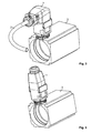
- Fig. 3 is a perspective view of a second embodiment of the plug-in connector 1 according to the invention for attaching a multi-wire cable 2 for transmitting power and signals to an electric motor 3, in the connected state.
- Fig. 4 is an exploded view of the plug-in connector 1 according to the invention from Fig. 3 .
- the plug-in connector 1 of the second embodiment of the invention according to Figs. 3 and 4 is constructed as an angle plug-in connector and includes the first and second features of the invention.
- the connection direction of the plug housings 5, 8 is orientated along or parallel to the axis of rotation about which the plug-in connector 1 can be rotatably mounted on the motor 3.
- Fig. 5 is a perspective view of a third embodiment of the plug-in connector 1 according to the invention for attaching a multi-wire cable 2 for transmitting power and signals to an electric motor 3, in the connected state.
- the plug-in connector 1 of the third embodiment of the invention is constructed as a linear plug-in connector and includes the first and second features of the invention.
- the connection direction of the plug housings 5, 8 is oriented along or parallel to the axis of rotation about which the plug-in connector 1 can be rotatably mounted on the motor 3.
- the cable 2 ( Fig. 1 ) is guided via the terminal 16 into the plug housing 5.
- the individual strands of the cable 2 are connected to the contact housings 7, still arranged outside the plug housing sockets 6, for transmitting power and signals via a cable grip (not shown).
- the contact housing 7 for signal transmission is then arranged in the socket 6 of the plug housing 5, which is shielded from electromagnetic radiation, and the contact housing 7 for power transmission is arranged in the adjacent socket 9 of the plug housing 5.
- a multi-wire motor feed cable (not shown) is guided via the terminal 17 into the plug housing 5 for attaching the motor-side plug housing 8 and the motor-side contact housing 10.
- the individual strands of the motor feed cable (not shown) are connected to the contact housings 10, still arranged outside the plug housing sockets 9, for transmitting power and signals via a cable grip (not shown).
- the contact housing 10 for signal transmission is then arranged in the socket 9 of the plug housing 8 which is shielded from electromagnetic radiation and the contact housing 10 for power transmission is arranged in the adjacent socket 9 of the plug housing 5.
- the plug housings 5, 8 can be divided to simplify the arrangement of the contact housings 7, 10 in the sockets 6, 9 of the plug housings 5, 8.
- the plug housing parts are preferably brought together prior to connection of the plug housings 5, 8.
- the terminal 17 of the motor-side plug housing 8 is then fastened rotatably on the flange 4 which is fastened on the housing of the motor 3.
- the guide projections 14 of the cable-side plug housing 5 are introduced into the guide links 12 of the locking device 11 in the connection direction of the plug housings 5, 8 (arrow in Fig. 2 ), and the locking device 11 is actuated in the locking direction (arrow in Fig. 2 ) oriented perpendicularly or transversely to the connection direction, in order to connect and lock the plug housings 5, 8 and the contact housings 7, 10.
- the plug-in connector 1 is fixed relative to the flange 4 by a union nut.
- the sequence of assembly steps is not predetermined and can be varied as desired.
- a plug-in connector system includes a plug-in connector 1 according to the invention corresponding to one of the aforementioned embodiments and at least two different contact housing pairs 7, 10 each with two connectable contact housings 7, 10, the contact housing pairs 7, 10 being equipped with different plug-in contact pairs.
- the same plug-in connector 1 can therefore be used in combination with different contact housing pairs 7, 10 or plug-in contact pairs selected, for example, from the applicant's HVS modular system.
Landscapes
- Details Of Connecting Devices For Male And Female Coupling (AREA)
- Connector Housings Or Holding Contact Members (AREA)
Applications Claiming Priority (1)
| Application Number | Priority Date | Filing Date | Title |
|---|---|---|---|
| DE102008005501 | 2008-01-22 |
Publications (3)
| Publication Number | Publication Date |
|---|---|
| EP2083485A2 true EP2083485A2 (fr) | 2009-07-29 |
| EP2083485A3 EP2083485A3 (fr) | 2012-05-02 |
| EP2083485B1 EP2083485B1 (fr) | 2020-01-08 |
Family
ID=40568804
Family Applications (1)
| Application Number | Title | Priority Date | Filing Date |
|---|---|---|---|
| EP09000809.5A Active EP2083485B1 (fr) | 2008-01-22 | 2009-01-21 | Connecteur électrique |
Country Status (1)
| Country | Link |
|---|---|
| EP (1) | EP2083485B1 (fr) |
Cited By (1)
| Publication number | Priority date | Publication date | Assignee | Title |
|---|---|---|---|---|
| US12451650B2 (en) | 2021-04-13 | 2025-10-21 | Te Connectivity Japan G.K. | Electrical connector and electrical connector assembly |
Citations (2)
| Publication number | Priority date | Publication date | Assignee | Title |
|---|---|---|---|---|
| EP0809331A1 (fr) | 1996-05-23 | 1997-11-26 | BKS Kabel-Service AG | Connecteur à fiche multipolaire ayant une prise avec au moins une fiche pour le raccordement électrique et mécanique des conducteurs électriques |
| US20020028604A1 (en) | 1998-01-15 | 2002-03-07 | Denny Lo | Enhanced performance telecommunications connector |
Family Cites Families (6)
| Publication number | Priority date | Publication date | Assignee | Title |
|---|---|---|---|---|
| US3760336A (en) * | 1971-03-24 | 1973-09-18 | Bunker Ramo | Miniature connector-modular |
| DE2712766A1 (de) * | 1977-03-23 | 1978-09-28 | Akzona Inc | Verwandelbarer zylindrischer elektrischer anschlusstecker |
| IT1154773B (it) * | 1980-04-15 | 1987-01-21 | Ca Ma Sas | Connettore multiplo componibile per sostegno di zoccoli portacontatti da applicarsi a listelli portaconnettori in impianti elettronici |
| JP3693137B2 (ja) * | 1996-08-05 | 2005-09-07 | 矢崎総業株式会社 | 電気接続箱の接続構造及び接続方法 |
| JP2005108510A (ja) * | 2003-09-29 | 2005-04-21 | Clarion Co Ltd | 多極型高周波同軸コネクタ |
| DE202005000883U1 (de) * | 2005-01-19 | 2005-05-04 | Coninvers Elektrotechnische Bauelemente Gmbh | Winkelsteckverbinder |
-
2009
- 2009-01-21 EP EP09000809.5A patent/EP2083485B1/fr active Active
Patent Citations (2)
| Publication number | Priority date | Publication date | Assignee | Title |
|---|---|---|---|---|
| EP0809331A1 (fr) | 1996-05-23 | 1997-11-26 | BKS Kabel-Service AG | Connecteur à fiche multipolaire ayant une prise avec au moins une fiche pour le raccordement électrique et mécanique des conducteurs électriques |
| US20020028604A1 (en) | 1998-01-15 | 2002-03-07 | Denny Lo | Enhanced performance telecommunications connector |
Cited By (1)
| Publication number | Priority date | Publication date | Assignee | Title |
|---|---|---|---|---|
| US12451650B2 (en) | 2021-04-13 | 2025-10-21 | Te Connectivity Japan G.K. | Electrical connector and electrical connector assembly |
Also Published As
| Publication number | Publication date |
|---|---|
| EP2083485A3 (fr) | 2012-05-02 |
| EP2083485B1 (fr) | 2020-01-08 |
Similar Documents
| Publication | Publication Date | Title |
|---|---|---|
| US11710926B2 (en) | Self-locking connector | |
| US10574001B2 (en) | High power electrical connector | |
| CN111525354B (zh) | 第一连接器、第二连接器及电连接器组件 | |
| US11424577B2 (en) | High-current electrical connector and electrical connector system | |
| KR100624582B1 (ko) | 케이블 상호 접속 장치 | |
| EP2686919B1 (fr) | Ensemble connecteur haute tension | |
| CN105659444B (zh) | 插拔连接器 | |
| JP6405360B2 (ja) | レセプタクル・キャリアを有するコネクタ組立体 | |
| US10892584B2 (en) | Socket-shaped housing, connector, and connector arrangement with cable support | |
| US10122135B2 (en) | Plug connector device having a wiring block with at least one receiving region | |
| CA2950018A1 (fr) | Fiche de raccordement | |
| CA2568267C (fr) | Ensemble a douille poignee hermaphrodite et ensemble a broche | |
| EP2426792A1 (fr) | Dispositif de connecteur de prise | |
| EP2083485B1 (fr) | Connecteur électrique | |
| US9209552B2 (en) | Connection module and connection module system | |
| US20240275084A1 (en) | Contact insert for an industrial plug connector | |
| EP3076492B1 (fr) | Système de connecteur électrique avec bras de libération faisant latéralement saillie | |
| CN113270749A (zh) | 连接器 | |
| KR101856382B1 (ko) | 커넥터 조립체 | |
| US20050266713A1 (en) | Hermaphroditic in-line handle and receptacle assembly | |
| CN121079852A (zh) | 用于工业插接连接器的插接连接器壳体的保持框架 | |
| JP6861464B2 (ja) | レバー式コネクタ |
Legal Events
| Date | Code | Title | Description |
|---|---|---|---|
| PUAI | Public reference made under article 153(3) epc to a published international application that has entered the european phase |
Free format text: ORIGINAL CODE: 0009012 |
|
| AK | Designated contracting states |
Kind code of ref document: A2 Designated state(s): AT BE BG CH CY CZ DE DK EE ES FI FR GB GR HR HU IE IS IT LI LT LU LV MC MK MT NL NO PL PT RO SE SI SK TR |
|
| AX | Request for extension of the european patent |
Extension state: AL BA RS |
|
| PUAL | Search report despatched |
Free format text: ORIGINAL CODE: 0009013 |
|
| AK | Designated contracting states |
Kind code of ref document: A3 Designated state(s): AT BE BG CH CY CZ DE DK EE ES FI FR GB GR HR HU IE IS IT LI LT LU LV MC MK MT NL NO PL PT RO SE SI SK TR |
|
| AX | Request for extension of the european patent |
Extension state: AL BA RS |
|
| RIC1 | Information provided on ipc code assigned before grant |
Ipc: H01R 13/514 20060101AFI20120329BHEP |
|
| 17P | Request for examination filed |
Effective date: 20120926 |
|
| AKX | Designation fees paid |
Designated state(s): AT BE BG CH CY CZ DE DK EE ES FI FR GB GR HR HU IE IS IT LI LT LU LV MC MK MT NL NO PL PT RO SE SI SK TR |
|
| RAP1 | Party data changed (applicant data changed or rights of an application transferred) |
Owner name: TE CONNECTIVITY GERMANY GMBH |
|
| 17Q | First examination report despatched |
Effective date: 20160823 |
|
| STAA | Information on the status of an ep patent application or granted ep patent |
Free format text: STATUS: EXAMINATION IS IN PROGRESS |
|
| GRAP | Despatch of communication of intention to grant a patent |
Free format text: ORIGINAL CODE: EPIDOSNIGR1 |
|
| STAA | Information on the status of an ep patent application or granted ep patent |
Free format text: STATUS: GRANT OF PATENT IS INTENDED |
|
| INTG | Intention to grant announced |
Effective date: 20190906 |
|
| GRAS | Grant fee paid |
Free format text: ORIGINAL CODE: EPIDOSNIGR3 |
|
| GRAA | (expected) grant |
Free format text: ORIGINAL CODE: 0009210 |
|
| STAA | Information on the status of an ep patent application or granted ep patent |
Free format text: STATUS: THE PATENT HAS BEEN GRANTED |
|
| AK | Designated contracting states |
Kind code of ref document: B1 Designated state(s): AT BE BG CH CY CZ DE DK EE ES FI FR GB GR HR HU IE IS IT LI LT LU LV MC MK MT NL NO PL PT RO SE SI SK TR |
|
| REG | Reference to a national code |
Ref country code: GB Ref legal event code: FG4D |
|
| REG | Reference to a national code |
Ref country code: CH Ref legal event code: EP |
|
| REG | Reference to a national code |
Ref country code: DE Ref legal event code: R096 Ref document number: 602009060927 Country of ref document: DE |
|
| REG | Reference to a national code |
Ref country code: IE Ref legal event code: FG4D |
|
| REG | Reference to a national code |
Ref country code: AT Ref legal event code: REF Ref document number: 1223842 Country of ref document: AT Kind code of ref document: T Effective date: 20200215 |
|
| REG | Reference to a national code |
Ref country code: NL Ref legal event code: MP Effective date: 20200108 |
|
| REG | Reference to a national code |
Ref country code: LT Ref legal event code: MG4D |
|
| PG25 | Lapsed in a contracting state [announced via postgrant information from national office to epo] |
Ref country code: FI Free format text: LAPSE BECAUSE OF FAILURE TO SUBMIT A TRANSLATION OF THE DESCRIPTION OR TO PAY THE FEE WITHIN THE PRESCRIBED TIME-LIMIT Effective date: 20200108 Ref country code: PT Free format text: LAPSE BECAUSE OF FAILURE TO SUBMIT A TRANSLATION OF THE DESCRIPTION OR TO PAY THE FEE WITHIN THE PRESCRIBED TIME-LIMIT Effective date: 20200531 Ref country code: NO Free format text: LAPSE BECAUSE OF FAILURE TO SUBMIT A TRANSLATION OF THE DESCRIPTION OR TO PAY THE FEE WITHIN THE PRESCRIBED TIME-LIMIT Effective date: 20200408 Ref country code: NL Free format text: LAPSE BECAUSE OF FAILURE TO SUBMIT A TRANSLATION OF THE DESCRIPTION OR TO PAY THE FEE WITHIN THE PRESCRIBED TIME-LIMIT Effective date: 20200108 Ref country code: LT Free format text: LAPSE BECAUSE OF FAILURE TO SUBMIT A TRANSLATION OF THE DESCRIPTION OR TO PAY THE FEE WITHIN THE PRESCRIBED TIME-LIMIT Effective date: 20200108 |
|
| PG25 | Lapsed in a contracting state [announced via postgrant information from national office to epo] |
Ref country code: HR Free format text: LAPSE BECAUSE OF FAILURE TO SUBMIT A TRANSLATION OF THE DESCRIPTION OR TO PAY THE FEE WITHIN THE PRESCRIBED TIME-LIMIT Effective date: 20200108 Ref country code: SE Free format text: LAPSE BECAUSE OF FAILURE TO SUBMIT A TRANSLATION OF THE DESCRIPTION OR TO PAY THE FEE WITHIN THE PRESCRIBED TIME-LIMIT Effective date: 20200108 Ref country code: LV Free format text: LAPSE BECAUSE OF FAILURE TO SUBMIT A TRANSLATION OF THE DESCRIPTION OR TO PAY THE FEE WITHIN THE PRESCRIBED TIME-LIMIT Effective date: 20200108 Ref country code: GR Free format text: LAPSE BECAUSE OF FAILURE TO SUBMIT A TRANSLATION OF THE DESCRIPTION OR TO PAY THE FEE WITHIN THE PRESCRIBED TIME-LIMIT Effective date: 20200409 Ref country code: IS Free format text: LAPSE BECAUSE OF FAILURE TO SUBMIT A TRANSLATION OF THE DESCRIPTION OR TO PAY THE FEE WITHIN THE PRESCRIBED TIME-LIMIT Effective date: 20200508 Ref country code: BG Free format text: LAPSE BECAUSE OF FAILURE TO SUBMIT A TRANSLATION OF THE DESCRIPTION OR TO PAY THE FEE WITHIN THE PRESCRIBED TIME-LIMIT Effective date: 20200408 |
|
| REG | Reference to a national code |
Ref country code: CH Ref legal event code: PL |
|
| REG | Reference to a national code |
Ref country code: DE Ref legal event code: R097 Ref document number: 602009060927 Country of ref document: DE |
|
| REG | Reference to a national code |
Ref country code: BE Ref legal event code: MM Effective date: 20200131 |
|
| PG25 | Lapsed in a contracting state [announced via postgrant information from national office to epo] |
Ref country code: LU Free format text: LAPSE BECAUSE OF NON-PAYMENT OF DUE FEES Effective date: 20200121 Ref country code: SK Free format text: LAPSE BECAUSE OF FAILURE TO SUBMIT A TRANSLATION OF THE DESCRIPTION OR TO PAY THE FEE WITHIN THE PRESCRIBED TIME-LIMIT Effective date: 20200108 Ref country code: EE Free format text: LAPSE BECAUSE OF FAILURE TO SUBMIT A TRANSLATION OF THE DESCRIPTION OR TO PAY THE FEE WITHIN THE PRESCRIBED TIME-LIMIT Effective date: 20200108 Ref country code: RO Free format text: LAPSE BECAUSE OF FAILURE TO SUBMIT A TRANSLATION OF THE DESCRIPTION OR TO PAY THE FEE WITHIN THE PRESCRIBED TIME-LIMIT Effective date: 20200108 Ref country code: DK Free format text: LAPSE BECAUSE OF FAILURE TO SUBMIT A TRANSLATION OF THE DESCRIPTION OR TO PAY THE FEE WITHIN THE PRESCRIBED TIME-LIMIT Effective date: 20200108 Ref country code: CZ Free format text: LAPSE BECAUSE OF FAILURE TO SUBMIT A TRANSLATION OF THE DESCRIPTION OR TO PAY THE FEE WITHIN THE PRESCRIBED TIME-LIMIT Effective date: 20200108 Ref country code: ES Free format text: LAPSE BECAUSE OF FAILURE TO SUBMIT A TRANSLATION OF THE DESCRIPTION OR TO PAY THE FEE WITHIN THE PRESCRIBED TIME-LIMIT Effective date: 20200108 Ref country code: MC Free format text: LAPSE BECAUSE OF FAILURE TO SUBMIT A TRANSLATION OF THE DESCRIPTION OR TO PAY THE FEE WITHIN THE PRESCRIBED TIME-LIMIT Effective date: 20200108 |
|
| PLBE | No opposition filed within time limit |
Free format text: ORIGINAL CODE: 0009261 |
|
| STAA | Information on the status of an ep patent application or granted ep patent |
Free format text: STATUS: NO OPPOSITION FILED WITHIN TIME LIMIT |
|
| REG | Reference to a national code |
Ref country code: AT Ref legal event code: MK05 Ref document number: 1223842 Country of ref document: AT Kind code of ref document: T Effective date: 20200108 |
|
| PG25 | Lapsed in a contracting state [announced via postgrant information from national office to epo] |
Ref country code: BE Free format text: LAPSE BECAUSE OF NON-PAYMENT OF DUE FEES Effective date: 20200131 Ref country code: LI Free format text: LAPSE BECAUSE OF NON-PAYMENT OF DUE FEES Effective date: 20200131 Ref country code: CH Free format text: LAPSE BECAUSE OF NON-PAYMENT OF DUE FEES Effective date: 20200131 |
|
| 26N | No opposition filed |
Effective date: 20201009 |
|
| PG25 | Lapsed in a contracting state [announced via postgrant information from national office to epo] |
Ref country code: AT Free format text: LAPSE BECAUSE OF FAILURE TO SUBMIT A TRANSLATION OF THE DESCRIPTION OR TO PAY THE FEE WITHIN THE PRESCRIBED TIME-LIMIT Effective date: 20200108 Ref country code: IE Free format text: LAPSE BECAUSE OF NON-PAYMENT OF DUE FEES Effective date: 20200121 Ref country code: IT Free format text: LAPSE BECAUSE OF FAILURE TO SUBMIT A TRANSLATION OF THE DESCRIPTION OR TO PAY THE FEE WITHIN THE PRESCRIBED TIME-LIMIT Effective date: 20200108 |
|
| PG25 | Lapsed in a contracting state [announced via postgrant information from national office to epo] |
Ref country code: SI Free format text: LAPSE BECAUSE OF FAILURE TO SUBMIT A TRANSLATION OF THE DESCRIPTION OR TO PAY THE FEE WITHIN THE PRESCRIBED TIME-LIMIT Effective date: 20200108 Ref country code: PL Free format text: LAPSE BECAUSE OF FAILURE TO SUBMIT A TRANSLATION OF THE DESCRIPTION OR TO PAY THE FEE WITHIN THE PRESCRIBED TIME-LIMIT Effective date: 20200108 |
|
| PG25 | Lapsed in a contracting state [announced via postgrant information from national office to epo] |
Ref country code: TR Free format text: LAPSE BECAUSE OF FAILURE TO SUBMIT A TRANSLATION OF THE DESCRIPTION OR TO PAY THE FEE WITHIN THE PRESCRIBED TIME-LIMIT Effective date: 20200108 Ref country code: MT Free format text: LAPSE BECAUSE OF FAILURE TO SUBMIT A TRANSLATION OF THE DESCRIPTION OR TO PAY THE FEE WITHIN THE PRESCRIBED TIME-LIMIT Effective date: 20200108 Ref country code: CY Free format text: LAPSE BECAUSE OF FAILURE TO SUBMIT A TRANSLATION OF THE DESCRIPTION OR TO PAY THE FEE WITHIN THE PRESCRIBED TIME-LIMIT Effective date: 20200108 |
|
| PG25 | Lapsed in a contracting state [announced via postgrant information from national office to epo] |
Ref country code: MK Free format text: LAPSE BECAUSE OF FAILURE TO SUBMIT A TRANSLATION OF THE DESCRIPTION OR TO PAY THE FEE WITHIN THE PRESCRIBED TIME-LIMIT Effective date: 20200108 |
|
| PGFP | Annual fee paid to national office [announced via postgrant information from national office to epo] |
Ref country code: GB Payment date: 20251204 Year of fee payment: 18 |
|
| PGFP | Annual fee paid to national office [announced via postgrant information from national office to epo] |
Ref country code: FR Payment date: 20251208 Year of fee payment: 18 |
|
| PGFP | Annual fee paid to national office [announced via postgrant information from national office to epo] |
Ref country code: DE Payment date: 20251203 Year of fee payment: 18 |