EP2083495A2 - Ensemble de batteries et méthode pour les charger - Google Patents
Ensemble de batteries et méthode pour les charger Download PDFInfo
- Publication number
- EP2083495A2 EP2083495A2 EP09151197A EP09151197A EP2083495A2 EP 2083495 A2 EP2083495 A2 EP 2083495A2 EP 09151197 A EP09151197 A EP 09151197A EP 09151197 A EP09151197 A EP 09151197A EP 2083495 A2 EP2083495 A2 EP 2083495A2
- Authority
- EP
- European Patent Office
- Prior art keywords
- secondary battery
- charging
- voltage
- battery
- ocv
- Prior art date
- Legal status (The legal status is an assumption and is not a legal conclusion. Google has not performed a legal analysis and makes no representation as to the accuracy of the status listed.)
- Granted
Links
Images

Classifications
-
- H—ELECTRICITY
- H02—GENERATION; CONVERSION OR DISTRIBUTION OF ELECTRIC POWER
- H02J—ELECTRIC POWER NETWORKS; CIRCUIT ARRANGEMENTS OR SYSTEMS FOR SUPPLYING OR DISTRIBUTING ELECTRIC POWER; SYSTEMS FOR STORING ELECTRIC ENERGY
- H02J7/00—Circuit arrangements for charging or discharging batteries or for supplying loads from batteries
- H02J7/02—Circuit arrangements for charging or discharging batteries or for supplying loads from batteries for charging batteries from AC mains by converters
- H02J7/04—Regulation of charging current or voltage
-
- H—ELECTRICITY
- H02—GENERATION; CONVERSION OR DISTRIBUTION OF ELECTRIC POWER
- H02J—ELECTRIC POWER NETWORKS; CIRCUIT ARRANGEMENTS OR SYSTEMS FOR SUPPLYING OR DISTRIBUTING ELECTRIC POWER; SYSTEMS FOR STORING ELECTRIC ENERGY
- H02J7/00—Circuit arrangements for charging or discharging batteries or for supplying loads from batteries
- H02J7/90—Regulation of charging or discharging current or voltage
- H02J7/96—Regulation of charging or discharging current or voltage in response to battery voltage
- H02J7/963—Regulation of charging or discharging current or voltage in response to battery voltage in response to battery voltage gradient
Definitions
- aspects of the present invention relate to a battery pack and a method of charging the same, and more particularly, to a battery pack in which reductions in stability and life span due to overcharge of the battery pack can be prevented, and a method of charging the same.
- the battery pack generally uses a nickel-cadmium (Ni-Cd) battery, a nickel-metal hydride (Ni-MH) battery or a lithium (Li) battery, which are rechargeable secondary batteries in consideration of the economic aspect.
- Ni-Cd nickel-cadmium
- Ni-MH nickel-metal hydride
- Li lithium
- a Li secondary battery can be classified into a Li ion battery using a liquid electrolyte and a lithium polymer battery using a polymer electrolyte according to the kind of the electrolyte, or classified into a cylindrical type, a prismatic type and a pouch type according to the shape of the battery.
- the Li secondary battery When the Li secondary battery is used in the battery pack, the Li secondary battery is electrically connected to a protection circuit board to prevent overcharge of the Li secondary battery during charging/discharging, or may be formed as a bare cell type to be electrically connected to the protection circuit board.
- the battery pack using the Li secondary battery may be charged using a constant current-constant voltage (CC/CV) method, which reduces a current applied to the battery pack by setting a constant voltage as a charging voltage, applying a constant current to the battery pack until a voltage of the battery pack reaches the set charging voltage, and maintaining the voltage applied to the battery pack to the charging voltage after the voltage of the battery pack reaches the set charging voltage.
- CC/CV constant current-constant voltage
- a section in which a constant current is applied to the battery pack is referred to as a constant current section (CC section), and a section in which a constant voltage is applied thereto is referred to as a constant voltage section (CV section).
- CC section constant current section
- CV section constant voltage section
- 1C means that the battery is charged with the same current as the rating capacity of the Li secondary battery.
- the capacity of the Li secondary battery is 1000mAh and a current amount applied for charging is 1000mAh, it is defined as 1C charge
- the applied current amount is 2000mAh
- 2C charge In this example, a C/20 charge would be 50mAh.
- the battery pack may already be fully charged before the charging current reaches C/20 in the CV section when the charging voltage applied for charging the battery pack is the maximum permissible charging voltage.
- the battery pack may be overcharged, and thus stability and life span of the battery pack may be reduced.
- aspects of the present invention provide a battery pack that can prevent overcharge regardless of a charging voltage applied to the battery pack by determining a charge completion time of the battery pack using an open circuit voltage (OCV) of the battery pack, and a method of charging the same.
- OCV open circuit voltage
- a first aspect of the invention provides the method of charging a battery pack including at least one secondary battery as set forth in claim 1.
- a second aspect of the invention provides the battery pack of claim 7.
- Preferred embodiments of the invention are subject of the dependent claims.
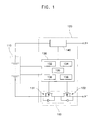
- FIG. 1 is a schematic view of a battery pack according to an embodiment of the present invention.
- the battery pack includes a battery assembly 110 including at least one bare cell or a secondary battery which is rechargeable, a battery management system 120 and external terminals P+ and P- electrically connecting the battery assembly 110 with an external power supply or load.
- the battery management system 120 includes a controller 130 that controls charging/discharging of the battery assembly, and a charge/discharge controller 150 that controls an electrical connection between the battery assembly 110 and the external terminals P+ and P- in response to a signal from the controller 130.
- the battery management system 120 may further include secondary protection devices 140 such as a fuse disposed on a high current path of the battery assembly 110 and blocking the electrical connection between the battery assembly 110 and the external terminals P+ and P-, a self-control protector (SCP) or a positive temperature coefficient (PTC) thermistor, in order to prevent the flow of overcurrent through the battery assembly 110 due to a malfunction of the controller 130 or the charge/discharge controller 150.
- secondary protection devices 140 such as a fuse disposed on a high current path of the battery assembly 110 and blocking the electrical connection between the battery assembly 110 and the external terminals P+ and P-, a self-control protector (SCP) or a positive temperature coefficient (PTC) thermistor, in order to prevent the flow of overcurrent through the battery assembly 110 due to a malfunction of the controller 130 or the charge/discharge controller 150.
- the controller 130 includes a voltage measuring part 132 that measures a charging voltage of the battery assembly 110, an open circuit voltage (OCV) measuring part 134 that measures an OCV of the battery assembly 110, a voltage comparing part 136 that compares the charging voltage and the OCV with a set voltage of the battery assembly 110, a full-charge/discharge detecting part 138 that determines whether or not the battery assembly is fully charged in response to a signal received from the voltage comparing part 136, and a protection circuit 135 that controls the charging/discharging of the battery assembly 110 according to a charged state of the battery assembly 110.
- OCV open circuit voltage
- the voltage comparing part 136 may include a first voltage comparing part (not separately illustrated) that compares the charging voltage of the battery assembly 110 with a first set voltage, and a second voltage comparing part (not illustrated) that compares the OCV of the battery assembly 110 with a second set voltage.
- the charge/discharge controller 150 includes a charge FET device 151 and a discharge FET device 152, and controls the charging/discharging of the battery assembly 110 by driving any one of the charge and discharge FET devices 151 and 152 by the control of the protection circuit 135 and the full-charge detecting part 138.
- the external terminals P+ and P- are connected parallel to the battery assembly 110, and comprise a positive electrode (P+) and a negative electrode (P-).
- the external terminals P+ and P- may electrically connect the electrode assembly 110 to the external power supply or load so as to charge or discharge the battery assembly 110. More specifically, when the external power supply is connected to the external terminals P+ and P-, the battery assembly 110 is charged, and when the load is connected to the external terminals P+ and P-, the battery assembly 110 is discharged.
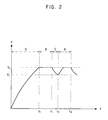
- FIG. 2 is a waveform of a charging voltage applied to the battery pack of FIG. 1
- FIG. 3 is a flowchart illustrating a method of charging a battery pack according to an embodiment of the present invention.
- the method resembles a conventional constant current-constant voltage (CC/CV) method in that the battery pack gradually increases a charging voltage applied to the battery assembly 110 to flow a constant current into the battery assembly 110, in a constant current section (indicated by reference character "A" in FIG. 2 ), in which the charging voltage applied to the battery assembly 110 reaches a first set voltage V0, (S01).
- the first set voltage V0 may be a charging voltage such as may be used in a constant voltage section in the conventional CC/CV method.
- the charging voltage applied to the battery assembly 110 is maintained at a voltage corresponding to the first set voltage V0 (S03) for a first set time period (t1-t0), as in the constant voltage section of the CC/CV method.
- the constant voltage section is indicated by reference character "B" in FIG. 2 .
- the charging voltage applied to the battery assembly 110 is interrupted (S04).
- a first set time period that is, the time period (t1-t0) of the constant voltage section B
- the time period of the constant voltage section B is too long, the same problems that occur in the conventional charging method may occur. That is, there may be overcharging of the battery assembly 110.
- the time period of the constant voltage section B is too short, the overall time taken to charge the battery pack increases.
- the charging voltage applied to the battery assembly 110 may be interrupted right after the charging voltage applied to the battery assembly 110 reaches the first set voltage V0 without maintaining the voltage at V0 for the first set time period.
- the open circuit voltage (OCV) of the battery assembly 110 is measured (S05).
- the OCV of the battery assembly 110 may be measured after expiration of the second set time period, that is, the time period (t2-t1) of the charge stop section C.
- the second set time period (t2-t1) of the charge stop section C may be shorter than the first set time period (t1-t0) of the constant voltage section B.
- the second set time period may be 5 to 10 seconds.
- the OCV of the battery assembly 110 is equal to or higher than a second set voltage is determined (S06). If the OCV is equal to or higher than the second set voltage, the charging of the battery assembly 110 is completed (S07). If the OCV of the battery assembly 110 is determined to be less than the second set voltage, a voltage corresponding to the first set voltage V0 is once again applied to the battery assembly 110 to charge the battery assembly 110 with a constant voltage for the first set time period (returning to S03).
- the first set voltage V0 is applied as the charging voltage to charge the battery assembly 110, even after the voltage of the battery assembly 110 decreases to a lower level V1 during to the charge stop section C, the charging voltage of the battery assembly 110 never exceeds the first set voltage V0.
- the charging of the battery assembly 110 in the constant voltage section B with the voltage corresponding to the first set voltage V0, the interrupting of the charging in the charge stop section C, the measuring of the OCV and the comparing of the OCV of the battery assembly 110 with the second set voltage are repeatedly performed.
- the battery pack according to the embodiment of the present invention determines the charge stop time by interrupting charging after a first set time period of charging at a constant voltage, measuring an OCV of the battery pack during or after a second set time period after the charging is interrupted and comparing the OCV with a first set voltage, so as to prevent overcharge of the battery pack even when the maximum permissible charging voltage is applied for charging the battery pack and thus to prevent decreases in stability and life span of the battery pack.
Landscapes
- Engineering & Computer Science (AREA)
- Power Engineering (AREA)
- Secondary Cells (AREA)
- Charge And Discharge Circuits For Batteries Or The Like (AREA)
Applications Claiming Priority (1)
| Application Number | Priority Date | Filing Date | Title |
|---|---|---|---|
| KR1020080007161A KR100998304B1 (ko) | 2008-01-23 | 2008-01-23 | 배터리 팩 및 이의 충전 방법 |
Publications (3)
| Publication Number | Publication Date |
|---|---|
| EP2083495A2 true EP2083495A2 (fr) | 2009-07-29 |
| EP2083495A3 EP2083495A3 (fr) | 2009-08-19 |
| EP2083495B1 EP2083495B1 (fr) | 2015-12-23 |
Family
ID=40643212
Family Applications (1)
| Application Number | Title | Priority Date | Filing Date |
|---|---|---|---|
| EP09151197.2A Active EP2083495B1 (fr) | 2008-01-23 | 2009-01-23 | Ensemble de batteries et méthode pour les charger |
Country Status (5)
| Country | Link |
|---|---|
| US (1) | US20090184685A1 (fr) |
| EP (1) | EP2083495B1 (fr) |
| JP (1) | JP5281843B2 (fr) |
| KR (1) | KR100998304B1 (fr) |
| CN (1) | CN101494306A (fr) |
Families Citing this family (26)
| Publication number | Priority date | Publication date | Assignee | Title |
|---|---|---|---|---|
| US8159191B2 (en) * | 2007-04-17 | 2012-04-17 | Tsun-Yu Chang | Advanced rechargeable battery system |
| US9559530B2 (en) | 2010-11-02 | 2017-01-31 | Navitas Solutions | Fault tolerant wireless battery area network for a smart battery management system |
| CN103270666B (zh) * | 2010-11-02 | 2018-01-30 | 纳维达斯解决方案有限公司 | 用于智能电池管理的无线电池区域网络 |
| US9564762B2 (en) | 2010-11-02 | 2017-02-07 | Navitas Solutions | Fault tolerant wireless battery area network for a smart battery management system |
| US20140078632A1 (en) * | 2012-09-18 | 2014-03-20 | Samsung Sdi Co., Ltd. | Battery pack, controlling method of the same, and energy storage system including the battery pack |
| CN104885325B (zh) | 2012-12-28 | 2019-03-08 | 工机控股株式会社 | 供电设备 |
| JP6418874B2 (ja) | 2014-01-15 | 2018-11-07 | 株式会社マキタ | バッテリパック |
| KR101586575B1 (ko) * | 2014-07-14 | 2016-01-21 | 김진수 | 2차전지의 충전시스템 및 충전방법 |
| KR102273766B1 (ko) * | 2014-08-26 | 2021-07-06 | 삼성에스디아이 주식회사 | 배터리 충전방법 및 이를 이용한 배터리 팩 |
| WO2017133400A2 (fr) | 2016-02-05 | 2017-08-10 | 广东欧珀移动通信有限公司 | Adaptateur et procédé de commande de charge |
| FI128680B (en) | 2017-03-02 | 2020-10-15 | Tespack Oy | Method, controlling unit and electronic charging arrangement for determining state of charge of a battery during charging of the battery |
| EP3480611B1 (fr) * | 2017-08-25 | 2022-12-28 | Guangdong Oppo Mobile Telecommunications Corp., Ltd. | Dispositif terminal, adaptateur et système et procédé de surveillance de la sécurité d'une batterie |
| KR102500690B1 (ko) * | 2017-09-18 | 2023-02-17 | 삼성전자주식회사 | 배터리 상태를 기반으로 충전을 제어하는 방법 및 장치 |
| JP7396813B2 (ja) * | 2019-06-06 | 2023-12-12 | パナソニック インテレクチュアル プロパティ コーポレーション オブ アメリカ | 開回路電圧計測方法、開回路電圧計測装置、及びプログラム |
| US11362536B2 (en) * | 2019-06-27 | 2022-06-14 | Motorola Solutions, Inc. | Methods and apparatus for detecting open circuit faults in a battery pack containing parallel cells |
| USD929336S1 (en) | 2019-09-05 | 2021-08-31 | Techtronic Cordless Gp | Electrical interface |
| USD929334S1 (en) | 2019-09-05 | 2021-08-31 | Techtronic Cordless Gp | Electrical interface |
| USD1013634S1 (en) | 2019-09-05 | 2024-02-06 | Techtronic Cordless Gp | Battery pack |
| USD953268S1 (en) | 2019-09-05 | 2022-05-31 | Techtronic Cordless Gp | Electrical interface |
| USD929338S1 (en) | 2019-09-05 | 2021-08-31 | Techtronic Cordless Gp | Electrical interface |
| USD929337S1 (en) | 2019-09-05 | 2021-08-31 | Techtronic Cordless Gp | Electrical interface |
| USD929339S1 (en) | 2019-09-05 | 2021-08-31 | Techtronic Cordless Gp | Electrical interface |
| USD929335S1 (en) | 2019-09-05 | 2021-08-31 | Techtronic Cordless Gp | Electrical interface |
| US20220309210A1 (en) * | 2021-03-24 | 2022-09-29 | The Boeing Company | Systems and methods for multi-conditional battery configuration |
| CN113489082B (zh) * | 2021-05-31 | 2023-07-04 | 上海航天电源技术有限责任公司 | 一种锂电池组充电方法及系统 |
| KR20240125135A (ko) * | 2023-02-10 | 2024-08-19 | 주식회사 엘지에너지솔루션 | 배터리 상태 진단 장치 및 방법 |
Family Cites Families (12)
| Publication number | Priority date | Publication date | Assignee | Title |
|---|---|---|---|---|
| US5523667A (en) * | 1992-01-27 | 1996-06-04 | Feldstein; Robert S. | Alkaline battery charger and method of operating same |
| US5352968A (en) * | 1992-05-28 | 1994-10-04 | Apple Computer, Inc. | Battery charge state determination |
| JPH07235332A (ja) * | 1994-02-24 | 1995-09-05 | Sanyo Electric Co Ltd | 二次電池の充電方法 |
| JP2000092737A (ja) * | 1998-09-11 | 2000-03-31 | Toshiba Battery Co Ltd | 二次電池の充電装置 |
| JP3929264B2 (ja) * | 2001-07-30 | 2007-06-13 | 富士通株式会社 | 二次電池の充電装置およびその方法 |
| CN100367627C (zh) * | 2002-05-17 | 2008-02-06 | 核心技术国际有限公司 | 充电电池的充电装置及充电方法 |
| US6930466B2 (en) * | 2002-12-17 | 2005-08-16 | Kyocera Wireless Corp. | Battery charger |
| US7429849B2 (en) * | 2003-11-26 | 2008-09-30 | Toyo System Co., Ltd. | Method and apparatus for confirming the charge amount and degradation state of a battery, a storage medium, an information processing apparatus, and an electronic apparatus |
| US7626362B2 (en) * | 2005-09-30 | 2009-12-01 | International Components Corporation | Rapid charge lithium ion battery charger |
| KR100954035B1 (ko) * | 2006-05-08 | 2010-04-20 | 삼성에스디아이 주식회사 | 이자전지 충전 방법 및 이차전지용 보호회로 장치 |
| JP4877181B2 (ja) * | 2006-10-23 | 2012-02-15 | ソニー株式会社 | 充電装置および充電方法 |
| US8378632B2 (en) * | 2007-10-02 | 2013-02-19 | The Gillette Company | Circuit arrangement with multiple batteries |
-
2008
- 2008-01-23 KR KR1020080007161A patent/KR100998304B1/ko active Active
- 2008-07-30 JP JP2008195839A patent/JP5281843B2/ja active Active
-
2009
- 2009-01-23 CN CNA2009100085329A patent/CN101494306A/zh active Pending
- 2009-01-23 US US12/358,623 patent/US20090184685A1/en not_active Abandoned
- 2009-01-23 EP EP09151197.2A patent/EP2083495B1/fr active Active
Also Published As
| Publication number | Publication date |
|---|---|
| KR20090081202A (ko) | 2009-07-28 |
| EP2083495A3 (fr) | 2009-08-19 |
| KR100998304B1 (ko) | 2010-12-03 |
| JP2009178017A (ja) | 2009-08-06 |
| US20090184685A1 (en) | 2009-07-23 |
| EP2083495B1 (fr) | 2015-12-23 |
| JP5281843B2 (ja) | 2013-09-04 |
| CN101494306A (zh) | 2009-07-29 |
Similar Documents
| Publication | Publication Date | Title |
|---|---|---|
| EP2083495B1 (fr) | Ensemble de batteries et méthode pour les charger | |
| US11735940B2 (en) | Methods and systems for recharging a battery | |
| EP2068420B1 (fr) | Procédé de chargement de batterie secondaire et dispositif | |
| KR102392376B1 (ko) | 배터리 시스템 | |
| US6756767B2 (en) | Method for charging and discharging battery based on charging capacity | |
| US9240696B2 (en) | Method and apparatus for recharging a battery | |
| US6850041B2 (en) | Battery pack used as power source for portable device | |
| US11418047B2 (en) | Battery charging method and system depending on ambient temperature | |
| US20190157896A1 (en) | Battery management apparatus and method for protecting a lithium iron phosphate cell from over-voltage using the same | |
| KR20050005554A (ko) | 재충전 가능한 배터리용 충전기 | |
| KR102564716B1 (ko) | 과방전으로부터 배터리를 보호하기 위한 배터리 관리 시스템과 방법 | |
| US20100102781A1 (en) | Apparatus and method for charging a battery | |
| US11114703B2 (en) | Battery pack | |
| EP1338074B1 (fr) | Limitation de temperature dans la charge de batterie au lithium | |
| EP1455194B1 (fr) | Dispositif et procédé pour charger des éléments de batterie | |
| US6459239B1 (en) | Method and apparatus for recharging batteries in the presence of a load current | |
| JPH09331636A (ja) | 二次電池の充電装置 | |
| CN104079025A (zh) | 用于延长锂离子和相似类型电池使用寿命的系统和方法 | |
| US20230029949A1 (en) | Battery pack and power tool system | |
| JP2000182677A (ja) | 二次電池充電装置 | |
| KR100536216B1 (ko) | 배터리 팩의 충전 방법 | |
| JP2002010504A (ja) | 電気自動車の電源装置 | |
| KR200374547Y1 (ko) | 휴대용 충전 장치 | |
| JP3555989B2 (ja) | 二次電池の充電方法 | |
| JPH0898427A (ja) | 充電装置 |
Legal Events
| Date | Code | Title | Description |
|---|---|---|---|
| PUAI | Public reference made under article 153(3) epc to a published international application that has entered the european phase |
Free format text: ORIGINAL CODE: 0009012 |
|
| PUAL | Search report despatched |
Free format text: ORIGINAL CODE: 0009013 |
|
| 17P | Request for examination filed |
Effective date: 20090123 |
|
| AK | Designated contracting states |
Kind code of ref document: A2 Designated state(s): AT BE BG CH CY CZ DE DK EE ES FI FR GB GR HR HU IE IS IT LI LT LU LV MC MK MT NL NO PL PT RO SE SI SK TR |
|
| AX | Request for extension of the european patent |
Extension state: AL BA RS |
|
| AK | Designated contracting states |
Kind code of ref document: A3 Designated state(s): AT BE BG CH CY CZ DE DK EE ES FI FR GB GR HR HU IE IS IT LI LT LU LV MC MK MT NL NO PL PT RO SE SI SK TR |
|
| AX | Request for extension of the european patent |
Extension state: AL BA RS |
|
| AKX | Designation fees paid |
Designated state(s): DE FR GB |
|
| 17Q | First examination report despatched |
Effective date: 20100426 |
|
| GRAP | Despatch of communication of intention to grant a patent |
Free format text: ORIGINAL CODE: EPIDOSNIGR1 |
|
| INTG | Intention to grant announced |
Effective date: 20150717 |
|
| GRAS | Grant fee paid |
Free format text: ORIGINAL CODE: EPIDOSNIGR3 |
|
| GRAA | (expected) grant |
Free format text: ORIGINAL CODE: 0009210 |
|
| AK | Designated contracting states |
Kind code of ref document: B1 Designated state(s): DE FR GB |
|
| REG | Reference to a national code |
Ref country code: GB Ref legal event code: FG4D |
|
| REG | Reference to a national code |
Ref country code: DE Ref legal event code: R096 Ref document number: 602009035338 Country of ref document: DE Ref country code: FR Ref legal event code: PLFP Year of fee payment: 8 |
|
| REG | Reference to a national code |
Ref country code: DE Ref legal event code: R097 Ref document number: 602009035338 Country of ref document: DE |
|
| PLBE | No opposition filed within time limit |
Free format text: ORIGINAL CODE: 0009261 |
|
| STAA | Information on the status of an ep patent application or granted ep patent |
Free format text: STATUS: NO OPPOSITION FILED WITHIN TIME LIMIT |
|
| 26N | No opposition filed |
Effective date: 20160926 |
|
| REG | Reference to a national code |
Ref country code: FR Ref legal event code: PLFP Year of fee payment: 9 |
|
| REG | Reference to a national code |
Ref country code: FR Ref legal event code: PLFP Year of fee payment: 10 |
|
| P01 | Opt-out of the competence of the unified patent court (upc) registered |
Effective date: 20230528 |
|
| PGFP | Annual fee paid to national office [announced via postgrant information from national office to epo] |
Ref country code: FR Payment date: 20251231 Year of fee payment: 18 |
|
| PGFP | Annual fee paid to national office [announced via postgrant information from national office to epo] |
Ref country code: GB Payment date: 20260106 Year of fee payment: 18 |
|
| PGFP | Annual fee paid to national office [announced via postgrant information from national office to epo] |
Ref country code: DE Payment date: 20251230 Year of fee payment: 18 |