EP2083505A1 - Machine dynamoélectrique dotée de bobines dentées agencées sur des corps de bobine - Google Patents
Machine dynamoélectrique dotée de bobines dentées agencées sur des corps de bobine Download PDFInfo
- Publication number
- EP2083505A1 EP2083505A1 EP07024857A EP07024857A EP2083505A1 EP 2083505 A1 EP2083505 A1 EP 2083505A1 EP 07024857 A EP07024857 A EP 07024857A EP 07024857 A EP07024857 A EP 07024857A EP 2083505 A1 EP2083505 A1 EP 2083505A1
- Authority
- EP
- European Patent Office
- Prior art keywords
- stator
- bobbin
- cover
- flange
- tooth
- Prior art date
- Legal status (The legal status is an assumption and is not a legal conclusion. Google has not performed a legal analysis and makes no representation as to the accuracy of the status listed.)
- Withdrawn
Links
- 238000004804 winding Methods 0.000 claims abstract description 26
- 230000004907 flux Effects 0.000 claims abstract description 4
- 238000004519 manufacturing process Methods 0.000 claims description 9
- 238000004080 punching Methods 0.000 claims description 4
- 239000002131 composite material Substances 0.000 claims description 2
- 238000000034 method Methods 0.000 description 9
- 230000001360 synchronised effect Effects 0.000 description 5
- 238000009413 insulation Methods 0.000 description 3
- 238000005266 casting Methods 0.000 description 2
- 210000003298 dental enamel Anatomy 0.000 description 2
- 238000004806 packaging method and process Methods 0.000 description 2
- 229910000831 Steel Inorganic materials 0.000 description 1
- 238000001816 cooling Methods 0.000 description 1
- 230000000694 effects Effects 0.000 description 1
- 238000010292 electrical insulation Methods 0.000 description 1
- 238000009434 installation Methods 0.000 description 1
- 238000002955 isolation Methods 0.000 description 1
- 238000000465 moulding Methods 0.000 description 1
- 238000000926 separation method Methods 0.000 description 1
- 239000010959 steel Substances 0.000 description 1
- 238000007651 thermal printing Methods 0.000 description 1
Images




Classifications
-
- H—ELECTRICITY
- H02—GENERATION; CONVERSION OR DISTRIBUTION OF ELECTRIC POWER
- H02K—DYNAMO-ELECTRIC MACHINES
- H02K3/00—Details of windings
- H02K3/46—Fastening of windings on the stator or rotor structure
- H02K3/52—Fastening salient pole windings or connections thereto
- H02K3/521—Fastening salient pole windings or connections thereto applicable to stators only
- H02K3/522—Fastening salient pole windings or connections thereto applicable to stators only for generally annular cores with salient poles
Definitions
- the invention relates to a dynamoelectric machine with a stator having a winding system arranged in grooves, wherein between the grooves teeth are arranged, and at least a part of these teeth is surrounded by a tooth coil, the teeth by a yoke back to each other for guiding the magnetic River, a rotor, in particular arranged in the stator bore, which interacts electromagnetically via an air gap between the stator and rotor with the stator, so that sets a rotational movement, wherein each tooth coil surrounds a bobbin, the tooth comprising a shaft and two flange-like Cover has.
- Dynamoelectric machines are basically provided with a winding system, which is normally located in grooves of a stator.
- the winding system is constructed for manufacturing reasons in some dynamoelectric machines from tooth coils, which are located on bobbins for ease of handling, manufacture and assembly.
- These bobbins are, such as from the DE 199 61 339 A1 known, placed on a star package and then inserted into a yoke back. These bobbins have a shaft and at its ends substantially parallel flange-like cover, which are arranged at right angles to the shaft. Especially with dynamoelectric machines of small diameter with a small number of grooves, the groove fill factor is thereby reduced or the sheet thickness of the yoke back is unnecessarily weakened.
- the Jochschen serves to guide the magnetic flux and may not be carried out radially so far too thin so as not to saturate.
- the present invention seeks to provide a dynamoelectric machine, in particular a high-pole permanent-magnet synchronous machine with high efficiency with low installation costs.
- a dynamoelectric machine with a stator having a slot-arranged in winding system, wherein between the grooves teeth are arranged, and at least a part of these teeth is surrounded by a respective tooth coil, the teeth by a yoke back to each other are connected to guide the magnetic flux, a rotor, in particular arranged in the stator bore, which interacts electromagnetically via an air gap between the stator and rotor with the stator, so that sets a rotational movement, each tooth coil surrounds a bobbin, comprising a tooth Shaft and two flange-like cover, wherein a cover facing the yoke back and the other cover the air gap, wherein the flange-like cover are made flexible, such that they are adaptable to the stator bore and / or the yoke back.
- the packaging can be done by stamped package, alternatively, the individual sheets of stator and / or rotor can also be welded or packaged by baked enamel method or by clamping bolts.
- the packaging can be done by stamped package, alternatively, the individual sheets of stator and / or rotor can also be welded or packaged by baked enamel method or by clamping bolts.
- the bobbin Due to the inventive design of the bobbin is now on the one hand a correct position compact winding possible, ie there is a high layer density of the respective wires regardless of the cross section of the winding wires before.
- the previous winding method such as needle winder or flyer due to the accessibility of the shaft of the bobbin can continue to be used, and thus sets a high Kupferdrall tint the dental coil.
- the bobbin with its tooth coil can now be adapted to the geometric conditions of the stator in a simple manner. That is, by the hinge effect or flexibility of the flange-like lid, the available in the grooves winding space can be utilized to the maximum. This results in a high Kupferglall tint a, while reducing "voids" in the groove.
- the flexibility of the flange-like lids to conform to the shape of the yoke or the stator bore can also be achieved by a thermal printing process during assembly of the wound bobbins onto the tooth.
- winding and bobbin is brought into the now final, for example, predetermined by the yoke shape and fixed.
- bobbins whether one-piece or multi-part design, are suitable for mounting from the direction of the stator bore, so one-piece stators, as well as for multi-part stators, which have a provided with tooth coils star package and a yoke back.
- the star package provided with tooth coils is inserted axially into a yoke back.
- FIG. 1 shows in a cross section a schematic representation of a stator 1, the air gap 11 facing teeth 2, wherein the teeth 2 are electromagnetically connected by a yoke back.
- tooth coils 9 are located.
- the tooth coils 9 are flanked radially by two parallel arranged perpendicular to the shaft 5 of the bobbin 4 covers 6 and 7th
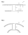
- a bobbin 4 is now according to FIG. 2 used, which also has a tooth 2 surrounding shaft 5, but the flange-like cover 6 and 7 are designed to be flexible or with hinge function.
- This hinge function is formed by recesses 8 which run substantially parallel to the axis in a cover 6, 7.
- both the flange-like cover 6 in the yoke back 3 and the air gap facing flange-like cover 7 is adapted to the course of the yoke back 3 on the groove base and the stator bore 12.
- FIG. 3 now shows an example in principle of how the flange-like cover 6 and 7 in this case in the installed state of the bobbin 4 in the stator 1 adapt.
- FIGS. 4 to 6 show further embodiments of the bobbin 4, which has an axial overlap of the cover 6, 7 at the end faces, and so in the assembled state in the stator 1 provides isolation of the tooth coil 9 with respect to the laminated core.
- the flange-like cover 7 is designed as a slot closure element, which may be formed at least partially magnetically conductive.
- each part of the bobbin 4 has a portion of the shaft 5 and a flange-like cover 6 or 7.
- the bobbin 4 this is first carried out with parallel and perpendicular to the shaft arranged flange-like lids 6 and 7 and wound with known winding process. Thereafter, the winding with the flange-like lids of the bobbin 4 is thermally deformed under pressure into the final shape suitable for the respective stator 1. This can be done in particular at the same time with a casting of the toothed coil 9 with the bobbins 4, so that even in this case a simple assembly and almost automated production is possible.
- the bobbin 4 according to the invention and the manufacturing method according to the invention are particularly suitable for permanent magnet synchronous machines and thereby both synchronous machines with internal rotor and with corresponding simple adjustments for external rotor.
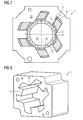
- the arrangement according to the invention and the method lead, in addition to the high utilization, to a cost-effective production, wherein the external dimensions of the dynamoelectric machine are comparatively low due to the adapted coil body, since the yoke back 3, in particular according to FIG FIG. 8 can be uniformly provided with a radially continuous thickness, without having areas that go into magnetic saturation.
- FIG. 9 is a spatial separation of the tooth coils 9 created by a respective unwound tooth 13 and thus an electrical insulation between the individual electrical phases.
- the stator 1 only three wound teeth 2, which are acted upon in a three-phase system with the phases U, V, W.
- Tabs 18, in particular attached to the cover 7 are suitable for fixing the toothed coil 9 in the operation of the dynamoelectric machine or as an assembly aid before casting, with a stator 1 after FIG. 11 results.
- FIG. 10 shows a two-part stator 1, which has a star package 17 and a yoke back 3.
- the wider teeth 2 are provided with bobbins 4, each having a tooth coil 9.
- the star package 17 is constructed by plates which are arranged axially alternately one behind the other and on the one hand have teeth which are connected together at their tooth tips and on the other individual teeth. The thus assembled laminated core has low leakage losses.
- FIG. 11 shows a stator 1, wherein the bobbin 4 are shed with their tooth coils 9 on the teeth 2.
- a shape design can be achieved, for example, leads a cooling air flow.
- the laminated core of the stator 1 is held and fixed by end plates 20, preferably made of high-strength steel
Landscapes
- Engineering & Computer Science (AREA)
- Power Engineering (AREA)
- Manufacture Of Motors, Generators (AREA)
- Insulation, Fastening Of Motor, Generator Windings (AREA)
Priority Applications (1)
| Application Number | Priority Date | Filing Date | Title |
|---|---|---|---|
| EP07024857A EP2083505A1 (fr) | 2008-01-28 | 2008-01-28 | Machine dynamoélectrique dotée de bobines dentées agencées sur des corps de bobine |
Applications Claiming Priority (1)
| Application Number | Priority Date | Filing Date | Title |
|---|---|---|---|
| EP07024857A EP2083505A1 (fr) | 2008-01-28 | 2008-01-28 | Machine dynamoélectrique dotée de bobines dentées agencées sur des corps de bobine |
Publications (1)
| Publication Number | Publication Date |
|---|---|
| EP2083505A1 true EP2083505A1 (fr) | 2009-07-29 |
Family
ID=39495027
Family Applications (1)
| Application Number | Title | Priority Date | Filing Date |
|---|---|---|---|
| EP07024857A Withdrawn EP2083505A1 (fr) | 2008-01-28 | 2008-01-28 | Machine dynamoélectrique dotée de bobines dentées agencées sur des corps de bobine |
Country Status (1)
| Country | Link |
|---|---|
| EP (1) | EP2083505A1 (fr) |
Cited By (5)
| Publication number | Priority date | Publication date | Assignee | Title |
|---|---|---|---|---|
| EP2677633A1 (fr) * | 2012-06-20 | 2013-12-25 | Valeo Equipements Electriques Moteur | Isolant de bobine mixte et élément de machine électrique associé |
| FR2992496A1 (fr) * | 2012-06-20 | 2013-12-27 | Valeo Equip Electr Moteur | Isolant de bobine muni de rainures pour faciliter l'impregnation de la bobine et element de machine electrique associe |
| FR2992493A1 (fr) * | 2012-06-20 | 2013-12-27 | Valeo Equip Electr Moteur | Isolant de bobine muni d'une ailette formant un mur electriquement isolant et element de machine electrique associe |
| DE102015225586A1 (de) * | 2015-12-17 | 2017-06-22 | Volkswagen Aktiengesellschaft | Spulenkörper für eine elektrische Spule |
| WO2021245116A1 (fr) * | 2020-06-03 | 2021-12-09 | Thyssenkrupp Presta Ag | Isolant électrique |
Citations (5)
| Publication number | Priority date | Publication date | Assignee | Title |
|---|---|---|---|---|
| JPH11234939A (ja) * | 1998-02-09 | 1999-08-27 | Japan Servo Co Ltd | コイルボビン |
| JP2000184631A (ja) * | 1998-12-18 | 2000-06-30 | Mitsubishi Electric Corp | ステータおよびその製造方法 |
| DE19961339A1 (de) | 1999-12-17 | 2001-07-05 | Siemens Ag | Elektrische Maschine |
| DE102004058046A1 (de) | 2004-12-01 | 2006-06-22 | Siemens Ag | Hochpolige permanenterregte Synchronmaschine mit Zahnspulen |
| JP2007124820A (ja) * | 2005-10-28 | 2007-05-17 | Nidec Shibaura Corp | モータ |
-
2008
- 2008-01-28 EP EP07024857A patent/EP2083505A1/fr not_active Withdrawn
Patent Citations (5)
| Publication number | Priority date | Publication date | Assignee | Title |
|---|---|---|---|---|
| JPH11234939A (ja) * | 1998-02-09 | 1999-08-27 | Japan Servo Co Ltd | コイルボビン |
| JP2000184631A (ja) * | 1998-12-18 | 2000-06-30 | Mitsubishi Electric Corp | ステータおよびその製造方法 |
| DE19961339A1 (de) | 1999-12-17 | 2001-07-05 | Siemens Ag | Elektrische Maschine |
| DE102004058046A1 (de) | 2004-12-01 | 2006-06-22 | Siemens Ag | Hochpolige permanenterregte Synchronmaschine mit Zahnspulen |
| JP2007124820A (ja) * | 2005-10-28 | 2007-05-17 | Nidec Shibaura Corp | モータ |
Cited By (8)
| Publication number | Priority date | Publication date | Assignee | Title |
|---|---|---|---|---|
| EP2677633A1 (fr) * | 2012-06-20 | 2013-12-25 | Valeo Equipements Electriques Moteur | Isolant de bobine mixte et élément de machine électrique associé |
| FR2992496A1 (fr) * | 2012-06-20 | 2013-12-27 | Valeo Equip Electr Moteur | Isolant de bobine muni de rainures pour faciliter l'impregnation de la bobine et element de machine electrique associe |
| FR2992493A1 (fr) * | 2012-06-20 | 2013-12-27 | Valeo Equip Electr Moteur | Isolant de bobine muni d'une ailette formant un mur electriquement isolant et element de machine electrique associe |
| FR2992494A1 (fr) * | 2012-06-20 | 2013-12-27 | Valeo Equip Electr Moteur | Isolant de bobine mixte et element de machine electrique associe |
| CN103516088A (zh) * | 2012-06-20 | 2014-01-15 | 法雷奥电机设备公司 | 组合的线圈绝缘体及相关的电机元件 |
| CN103516088B (zh) * | 2012-06-20 | 2016-05-11 | 法雷奥电机设备公司 | 组合的线圈绝缘体及相关的电机元件 |
| DE102015225586A1 (de) * | 2015-12-17 | 2017-06-22 | Volkswagen Aktiengesellschaft | Spulenkörper für eine elektrische Spule |
| WO2021245116A1 (fr) * | 2020-06-03 | 2021-12-09 | Thyssenkrupp Presta Ag | Isolant électrique |
Similar Documents
| Publication | Publication Date | Title |
|---|---|---|
| EP1114500B1 (fr) | Moteur electrique | |
| EP2179488B1 (fr) | Stator pour moteur électrique | |
| EP2647109B1 (fr) | Procédé de fabrication d'un enroulement de stator d'un moteur électrique, notamment de fabrication d'un générateur de courant alternatif | |
| DE112012003962T5 (de) | Rotierende elektrische Maschine und Verfahren zur Herstellung der rotierenden elektrischen Maschine | |
| DE102005045348A1 (de) | Zahnmodul für ein permanentmagneterregtes Primärteil einer elektrischen Maschine | |
| DE102008056934A1 (de) | Maschine mit konzentrierten Wicklungen mit magnetischen Schlitzkeilen | |
| EP2071707A1 (fr) | Machine dynamoélectrique dotée de bobines dentées | |
| DE102020129142B4 (de) | Läufer für eine rotierende elektrische Maschine | |
| DE102009024230A1 (de) | Verfahren zur Herstellung einer Ständerwicklung einer elektrischen Maschine, insbesondere zur Herstellung eines Wechselstromgenerators | |
| DE102012100332A1 (de) | Stator für eine rotierende elektrische Maschine und Verfahren zu seiner Herstellung | |
| DE102012022868A1 (de) | Stator einer elektrischen Maschine und Verfahren zur Herstellung eines Stators | |
| WO2018192817A1 (fr) | Module de dent polaire pour une machine électrique, pièce active pourvue d'un module de dent polaire et machine électrique | |
| DE102012224012A1 (de) | Spulenkörper zur Montage an einem Magnetkern, Reluktanzresolver und Verfahren zur Herstellung | |
| DE102010038486A1 (de) | Wicklungen mit eckigem Querschnitt für Rotoren von elektrischen Maschinen | |
| EP2083505A1 (fr) | Machine dynamoélectrique dotée de bobines dentées agencées sur des corps de bobine | |
| DE112013001643T5 (de) | Elektrische rotierende Maschine | |
| EP3488516B1 (fr) | Stator d'un machine à courant alternatif | |
| EP3216113B1 (fr) | Rotor or stator avec tête de bobinage emboîté courte | |
| EP3547501A1 (fr) | Segment de stator | |
| DE102006050201A1 (de) | Transversalflussmaschine und Verfahren zur Herstellung einer Transversalflussmaschine | |
| DE10338452A1 (de) | Verfahren zur Herstellung eines Bauteils mit einer Spule sowie elektrische Maschine mit derartigem Bauteil | |
| DE102013226149A1 (de) | Maschinenkomponente für eine elektrische Maschine und Verfahren zur Herstellung einer Maschinenkomponente | |
| EP3167540B1 (fr) | Procédé de fabrication d'une machine électrique comportant des bobines formées et machine électrique et outil de fabrication | |
| EP2337195A2 (fr) | Entraînement linéaire avec une réduction des courants de Foucault | |
| DE102009001543A1 (de) | Elektrische Maschine und Verfahren zur Herstellung einer elektrischen Maschine |
Legal Events
| Date | Code | Title | Description |
|---|---|---|---|
| PUAI | Public reference made under article 153(3) epc to a published international application that has entered the european phase |
Free format text: ORIGINAL CODE: 0009012 |
|
| AK | Designated contracting states |
Kind code of ref document: A1 Designated state(s): AT BE BG CH CY CZ DE DK EE ES FI FR GB GR HU IE IS IT LI LT LU LV MC MT NL PL PT RO SE SI SK TR |
|
| AX | Request for extension of the european patent |
Extension state: AL BA HR MK RS |
|
| STAA | Information on the status of an ep patent application or granted ep patent |
Free format text: STATUS: THE APPLICATION HAS BEEN WITHDRAWN |
|
| 18W | Application withdrawn |
Effective date: 20090902 |