EP2083697B1 - Intraorale dentale radiologie-positionierungsvorrichtung zur verwendung mit einem röntgenrezeptor - Google Patents
Intraorale dentale radiologie-positionierungsvorrichtung zur verwendung mit einem röntgenrezeptor Download PDFInfo
- Publication number
- EP2083697B1 EP2083697B1 EP07839804.7A EP07839804A EP2083697B1 EP 2083697 B1 EP2083697 B1 EP 2083697B1 EP 07839804 A EP07839804 A EP 07839804A EP 2083697 B1 EP2083697 B1 EP 2083697B1
- Authority
- EP
- European Patent Office
- Prior art keywords
- arm
- opening
- receptor
- collimation
- patient
- Prior art date
- Legal status (The legal status is an assumption and is not a legal conclusion. Google has not performed a legal analysis and makes no representation as to the accuracy of the status listed.)
- Not-in-force
Links
- 229910052751 metal Inorganic materials 0.000 claims description 18
- 239000002184 metal Substances 0.000 claims description 18
- 230000005855 radiation Effects 0.000 claims description 13
- 239000000463 material Substances 0.000 claims description 6
- 150000001875 compounds Chemical class 0.000 claims description 3
- 230000005484 gravity Effects 0.000 claims description 3
- 102000005962 receptors Human genes 0.000 description 98
- 238000000034 method Methods 0.000 description 9
- 230000008901 benefit Effects 0.000 description 7
- 238000013461 design Methods 0.000 description 6
- 210000004513 dentition Anatomy 0.000 description 5
- 238000007373 indentation Methods 0.000 description 5
- 230000036346 tooth eruption Effects 0.000 description 5
- 210000003484 anatomy Anatomy 0.000 description 4
- 210000000988 bone and bone Anatomy 0.000 description 4
- 239000004033 plastic Substances 0.000 description 3
- 229910001220 stainless steel Inorganic materials 0.000 description 3
- 239000010935 stainless steel Substances 0.000 description 3
- 239000004677 Nylon Substances 0.000 description 2
- 208000006650 Overbite Diseases 0.000 description 2
- 239000004743 Polypropylene Substances 0.000 description 2
- 238000010521 absorption reaction Methods 0.000 description 2
- 230000001154 acute effect Effects 0.000 description 2
- 230000015556 catabolic process Effects 0.000 description 2
- 230000008859 change Effects 0.000 description 2
- 230000001010 compromised effect Effects 0.000 description 2
- 238000010276 construction Methods 0.000 description 2
- 230000003247 decreasing effect Effects 0.000 description 2
- 238000006731 degradation reaction Methods 0.000 description 2
- 238000003780 insertion Methods 0.000 description 2
- 230000037431 insertion Effects 0.000 description 2
- 238000012986 modification Methods 0.000 description 2
- 230000004048 modification Effects 0.000 description 2
- 229920001778 nylon Polymers 0.000 description 2
- 208000028169 periodontal disease Diseases 0.000 description 2
- -1 polypropylene Polymers 0.000 description 2
- 229920001155 polypropylene Polymers 0.000 description 2
- 230000001954 sterilising effect Effects 0.000 description 2
- 239000000126 substance Substances 0.000 description 2
- 238000003466 welding Methods 0.000 description 2
- 206010061274 Malocclusion Diseases 0.000 description 1
- 102000016979 Other receptors Human genes 0.000 description 1
- 230000009471 action Effects 0.000 description 1
- 238000005452 bending Methods 0.000 description 1
- 230000007812 deficiency Effects 0.000 description 1
- 238000003745 diagnosis Methods 0.000 description 1
- 238000004980 dosimetry Methods 0.000 description 1
- 238000002347 injection Methods 0.000 description 1
- 239000007924 injection Substances 0.000 description 1
- 238000012423 maintenance Methods 0.000 description 1
- 210000004373 mandible Anatomy 0.000 description 1
- 239000011159 matrix material Substances 0.000 description 1
- 230000008520 organization Effects 0.000 description 1
- 239000000843 powder Substances 0.000 description 1
- 238000002601 radiography Methods 0.000 description 1
- 230000002787 reinforcement Effects 0.000 description 1
- 238000007142 ring opening reaction Methods 0.000 description 1
- 238000004659 sterilization and disinfection Methods 0.000 description 1
- 210000001519 tissue Anatomy 0.000 description 1
- WFKWXMTUELFFGS-UHFFFAOYSA-N tungsten Chemical compound [W] WFKWXMTUELFFGS-UHFFFAOYSA-N 0.000 description 1
- 229910052721 tungsten Inorganic materials 0.000 description 1
- 239000010937 tungsten Substances 0.000 description 1
Images


Classifications
-
- G—PHYSICS
- G03—PHOTOGRAPHY; CINEMATOGRAPHY; ANALOGOUS TECHNIQUES USING WAVES OTHER THAN OPTICAL WAVES; ELECTROGRAPHY; HOLOGRAPHY
- G03B—APPARATUS OR ARRANGEMENTS FOR TAKING PHOTOGRAPHS OR FOR PROJECTING OR VIEWING THEM; APPARATUS OR ARRANGEMENTS EMPLOYING ANALOGOUS TECHNIQUES USING WAVES OTHER THAN OPTICAL WAVES; ACCESSORIES THEREFOR
- G03B42/00—Obtaining records using waves other than optical waves; Visualisation of such records by using optical means
- G03B42/02—Obtaining records using waves other than optical waves; Visualisation of such records by using optical means using X-rays
- G03B42/04—Holders for X-ray films
- G03B42/042—Holders for X-ray films for dental applications
-
- A—HUMAN NECESSITIES
- A61—MEDICAL OR VETERINARY SCIENCE; HYGIENE
- A61B—DIAGNOSIS; SURGERY; IDENTIFICATION
- A61B6/00—Apparatus or devices for radiation diagnosis; Apparatus or devices for radiation diagnosis combined with radiation therapy equipment
- A61B6/44—Constructional features of apparatus for radiation diagnosis
- A61B6/4429—Constructional features of apparatus for radiation diagnosis related to the mounting of source units and detector units
- A61B6/4435—Constructional features of apparatus for radiation diagnosis related to the mounting of source units and detector units the source unit and the detector unit being coupled by a rigid structure
-
- A—HUMAN NECESSITIES
- A61—MEDICAL OR VETERINARY SCIENCE; HYGIENE
- A61B—DIAGNOSIS; SURGERY; IDENTIFICATION
- A61B6/00—Apparatus or devices for radiation diagnosis; Apparatus or devices for radiation diagnosis combined with radiation therapy equipment
- A61B6/50—Apparatus or devices for radiation diagnosis; Apparatus or devices for radiation diagnosis combined with radiation therapy equipment specially adapted for specific body parts; specially adapted for specific clinical applications
- A61B6/51—Apparatus or devices for radiation diagnosis; Apparatus or devices for radiation diagnosis combined with radiation therapy equipment specially adapted for specific body parts; specially adapted for specific clinical applications for dentistry
- A61B6/512—Intraoral means
Definitions
- the present invention relates to devices for dental radiographic procedures or intraoral diagnostics, and more particularly, to intraoral dental radiology positioning devices relating to positioning x-ray film or receptors in a patient's mouth during radiographic procedures.
- Intraoral x-ray diagnosis involves positioning an x-ray film within a patient's mouth next to the inner surface of the teeth or bone being studied. The film is then exposed to an x-ray beam generated outside the mouth and passing through the target.
- Known intraoral dental radiography typically employs a dental device having an alignment member including an x-ray film holding structure at one end, an aligning arm at another end, and a bite plate positioned between the ends.
- the alignment member also known as an aiming ring
- a commonly prescribed dental radiograph is the "bitewing", whereby an image is acquired of the crowns of the teeth biting together and their surrounding socket bone.
- film mounted in a holder that includes a bite block portion extending from the film in the direction of the external x-ray tube. The patient bites down on the bite block with the target teeth and holds the film in position next to the target.
- a disadvantage of known devices is that the cross-sectional area of the beam used by the radiographic technique is typically larger than the surface area of the x-ray film.
- the cross-sectional area of the beam does not match the film size, the patient can be exposed to unnecessary radiation that irradiates tissues beyond the borders of the dental film.
- Typical film positioning instruments may also allow unwanted x-radiation to pass through the film holding instrument.
- Another disadvantage of current x-ray film positioning instruments is that there can be errors in aiming the x-ray. These errors are frequently associated with a rectangular position-indicating device attached to an x-ray machine. Also, there can be errors in orientation of the long axis of the substantially rectangular typical position indicating devices with the long axis of the film in the patient's mouth. Aiming and orientation errors expose the patient to needless retakes of radiographs. Moreover, if a rectangular positioning device is used, it must be specifically oriented for vertical or horizontal receptor orientation, and must be re-positioned if the receptor orientation is changed.
- a further disadvantage of current x-ray film positioning instruments is that the patient can only bite on the bite plate to assist in positioning and holding a film positioning device in the mouth.
- Typical devices may be difficult to grasp and manipulate in the patient's mouth making it problematic for the patient to assist in positioning the instrument, particularly during the x-ray exposure itself.
- US Patent 3,745,344 describes an intradent radiographic system for substantially confining the X-ray beam to the film as defined in the pre-characterising portion of claim 1 below.
- the collimation plate may be made of a metal or a high gravity compound, and further includes polymeric grips on the handles incorporating the arm holder, with the collimation plate having a cut-out portion adjacent a base of the handle through which the arm-receiving opening of the polymeric arm holder extends.
- the device may include a pair of handles, each handle having a polymeric portion with an arm-receiving opening, wherein one of the handles is radially aligned with the collimation plate opening and the other of the handles is non-radially aligned with the collimation plate opening.
- the arm-receiving opening of the arm holder is rectangular and the collimation plate has a cut-out portion adjacent a base of the handle on at least two sides of the rectangular arm-receiving opening.
- each handle has an arm holder with an arm-receiving rectangular opening, with one of the arm-receiving rectangular openings being radially aligned with the collimation plate opening and the other of the arm-receiving rectangular openings being non-radially aligned with the collimation plate opening.
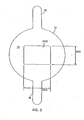
- the receptor positioning device includes a substantially flat collimation plate 12, having a surface area 14.
- the surface area 14 defines a substantially central rectangular opening 16.
- the collimation plate 12 further includes opposing elongated handles 18 extending outward on opposite sides thereof.
- the receptor positioning instrument 10 further includes an elongated arm 20 and a film or electronic receptor holding member 28 having a back plate 30 and clips 32 for holding x ray film or electronic receptors.
- the elongated arm 20 is connected at a bent first end 40 to the back of the collimation plate 50, preferably, by welding or other rigid connection.
- the elongated arm further includes a second end 22 attached to the rear surface 52 of the back plate 30 of the receptor holding member 28, opposite collimator plate 12.
- the film or electronic receptor holding member 28 back plate 30 is preferably of metal and the opposing clips 32 are designed and adapted to receive and grasp a removable film or digital-electronic receptor 54.
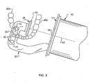
- the elongated arm 20 includes a flat upper surface 26 adapted to receive a patient's teeth.
- the patient's teeth 60a on one side of the mouth are positioned to grip the substantially flat biting surface 26 of the elongated arm 20, as shown in Fig. 3 .
- the biting surface receiving portion is normally incompressible.
- biting surface 26 on arm 20, behind the receptor plate 54 includes a plurality of circular perforations or openings, for example the three 6 mm diameter openings 70 longitudinally spaced 8 mm apart as shown in Fig. 3 .
- a curable elastomeric impression material 72 on either side of biting surface 26 (see also Figs. 4-6 , which may be used to create and register with the unique occlusion pattern of the patient's teeth, as also shown in Fig. 11 .
- This registration may be removed, archived and reused to create reproducible x-ray images of the teeth in repeated sequential exposures over time.
- the film or receptor 54 held on the back plate 30 by the clips 32 of the receptor holding member 28 is positioned behind the desired teeth 60b to be exposed, on the opposite side of the patient's mouth.
- the back plate 30 and receptor 54 are parallel to collimation plate 12.
- the film or receptor 54 is thereby positioned to be exposed to an x-ray from the x-ray machine 62 to show the condition of teeth 60b, as shown further in Fig. 11 .
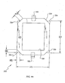
- the collimation plate 12 further includes a preferably rectangular opening 200 positioned substantially in the center of the collimation plate 12.
- the opening 16 has a vertical dimension 202, and a horizontal dimension 204.
- the vertical dimension 202 of the opening is about 3.1 cm (1.210 in.)
- the horizontal dimension 204 is preferably about 3.9 cm (1.552 in.).
- the collimation plate 12 is adapted to axially align the x-ray machine's position indicating cylinder device 62 with the receptor 54, as shown by the x-ray centerline 63. It does this in two ways. First, the x-ray machine is easily centered because the two devices, 12, 62, have substantially the same diameter.
- Axial offset would be apparent by extension of the outer edge of collimation plate 12 beyond the outer rim of the x-ray machine position indicating cylinder device 62.
- the orientation and size of the rectangular collimation opening described above is for use with the adult size horizontal bitewing radiographic examination of patients with normal anatomy and dentitions. Other sizes may be made for small children or for other uses.
- existing commercially available metal collimation plates generally have on the order of 1.27 mm (0.050 in.) thickness, the inventor's dosimetry studies have shown that this thickness still permits a substantial amount of radiation to penetrate and expose the patient to needless additional radiation.
- the thickness T of the collimation plate ( Fig. 4 ) has at least 1.9 mm (0.075 in.) thickness, more preferably 2.0 mm (0.080) or 2.5 mm (0.100 in.) or more to block such excess radiation.
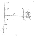
- the substantially flat elongated arm 20 of the preferred embodiment shown in Fig. 1 is shown including the first end 40, the second end 22, a short member 23 (on which biting surface 26 is located) having a first length 25, and an angled portion 21.
- Fig. 5 shows arm 20 as a flat blank prior to forming at the dotted lines, while Fig. 6 shows arm 20 after forming, where both ends 22 and 40 are bent approximately 90°.
- the second end 22 of the elongated arm 20, and the outer edge of the angled portion 21 define a first dimension 27.
- the first dimension 27 is preferably about 1.25 in. (3.2 cm), and the first length 25 is preferably about 6.45 cm (2.54 in.).
- the outer edge of the short member 23 and the vertical plane define an angle 29 which determines the angulation of the short member 23 of the elongated arm 20.
- the preferred angle 29 is about 12°.
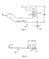
- FIG. 7 shows another embodiment of an elongated arm 100 which can be used with the receptor positioning device 10 shown in Figs. 1-4 .
- the elongated arm 100 includes the first end 40, the second end 22, the angled portion 21, and the short member 23 as in the embodiment shown in Figs. 5 and 6 .
- Fig. 7 shows arm 20 as a flat blank prior to forming at the dotted lines
- Fig. 8 shows arm 20 after forming, where both ends 22 and 40 are bent approximately 90°.
- the short member has a second length 106 which is more than the dimension 25 of the embodiment shown in Figs. 1 and 5-6 .
- the second length 106 is preferably about 7.2 cm (2.85 in.).
- the second end 22 of the elongated arm 20, and the outer edge of the angled portion 21 define a second dimension 104 which is less than the first dimension 27 of the embodiment shown in Figs. 1 and 5-6 .
- the second dimension 104 is less than the first dimension shown in Fig. 5 and preferably about 2.8 cm (1.10 in.).
- the outer edge of the short member 23 and the vertical plane define an angle 108 which is less than or more acute than the angle 29 of the embodiment shown in Figs. 5 and 6 and is preferably about 7°. The more acute angle 108 better accommodates deep overbite occlusions.
- This other embodiment of the elongated arm has a dimension that is easily accommodated in mouths that have anatomy with deep overbites (retrognathic mandibles) ranging in size from that of a child to a large adult.
- the collimation plate 12 further includes a preferably rectangular opening 210 positioned substantially in the center of the collimation plate 12, where the length of the opening 210 is smaller than the width.
- the opening 210 has a vertical dimension 212, and a horizontal dimension 214.
- the vertical dimension 212 of the opening is preferably about 3.9 cm (1.552 in.)
- the horizontal dimension 214 is preferably about 3.1 cm (1.210 in.). This embodiment offers a different positioning of the opening to correspond to an adult receptor or film held in the receptor holding member 28.
- the orientation and size of the rectangular collimation opening is for use with the adult size vertical bitewing radiographic examination. This is useful for observing compromised dentitions (with large restorations and height of alveolar crest bone decreased by marginal periodontal disease) that would not be visualized on horizontal bitewing images.
- the collimation plate 12 further includes a preferably rectangular opening 220 positioned substantially in the center of the collimation plate 12.
- the opening 220 has a vertical dimension 222, and a horizontal dimension 224.
- the vertical dimension 222 of the opening is about 2.5 cm (1.000 in.)
- the horizontal dimension 224 is preferably about 3.9 cm (1.552 in.).
- This embodiment is designed to correspond to a child's receptor or film held in the receptor holding member 28.
- the size and orientation of the rectangular collimation opening is for use for horizontal bitewing examinations in small children (4-8 years) and very small adults or adults with limited ability to open their mouths.
- the back plate 30 is shown of the device of Fig. 1 .
- Fig. 12 shows the flat blank for plate 30 and
- Fig. 13 shows plate 30 after forming.
- the back plate 30 includes the clips 32 and preferably has an overall length 36 of about 1.71 in. (4.3 cm), and a dimension between the clips 38 of preferably about 4.0 cm (1.578 in.), as they are shown formed and curled in Fig. 13 .
- the referred dimension 34 between the back plate 30 and the formed clip 32 is about 1.3 mm (0.05 in.).
- the width 35 of the back plate 30 is preferably about 3.05 cm (1.20 in.). The dimensions herein accommodate standard intraoral dental film.
- FIG. 14 shows the flat blank for plate 30
- Fig. 15 shows plate 30 after forming.
- the embodiment shown in Figs. 14 and 15 is the same as in the embodiment shown in Figs. 12 and 13 except in the addition of two opposing notches 39. These notches are on opposite sides of the back plate and are on adjacent sides with reference to the clips 32.
- the notches 39 are a specified dimension 31 from the midpoint of the long side of the back plate 30.
- the dimension 31 is preferably about 3.8 mm (0.15 in.).
- the notches 39 accept electronic receptors to the back plate 30 of the receptor holding member 28 with the aid of orthodontic elastics (not shown).
- Fig. 16 shows receptor 54 held in place on receptor holding member 28 by a pair of orthodontic elastic bands 76 which are received in two spaced pairs of notches 39.
- the receptor 54 is a digital-electronic receptor
- data cord 78 extending from the receptor may be secured to and along elongated arm 20 by connector 80, between the collimation plate and the receptor holding member, so that data plug 82 may be positioned outside the patient's mouth.
- back plate sizes may be used, such as one designed for receptors or film used for children which is smaller than the films used with the back plates shown in Figs. 12-15 .
- Such a back plate would preferably have a length between the curled clips of about 4.1 cm (1.60 in.) long similar to the embodiments shown in Figs 12-15 , but, a width of preferably about 2.5 cm (1.00 in.) wide to accommodate size film designed for children.
- the patient's mouth 65 is outlined and the patient's teeth are above and below the elongated arm 20 of the receptor positioning device 10. Teeth 60a bite down on and grip biting portion 26 of arm 20. Biting portion 26 may contain elastomeric impression material which conforms to the occlusion pattern of the patient's teeth 60a.
- the receptor holding member 28 is positioned behind the teeth 60b to be exposed (on the opposite side of the mouth from teeth 60a) and the collimation plate 12 is positioned in adjacent to the patient's mouth 65 and teeth 60b.
- the x-ray machine 62 is positioned to take an x-ray in front of the collimation plate 12 and expose the x-ray film receptor 54.
- the patient or radiographer may use handles 18 to reposition the receptor positioning device for better comfort or aim.
- the collimation plate 12 is constructed of a metal and rigidly and fixedly fashioned.
- the rigid and fixed construction of the receptor positioning device 10 provides the most accurate film exposure because there is minimal opportunity for unwanted movement after positioning the device.
- the metal collimation plate having a rectangular opening 16 reduces patient exposure by absorbing approximately 50% of primary beam x-radiation for the most commonly prescribed dental radiograph, which is the bitewing. Further, the metal collimation plate reduces aiming error, that is, "cone cuts", which are frequently associated with the rectangular position-indicating device attached to the x-ray machine.
- collimation plate of the present invention having a rectangular opening 16 reduces patient exposure to x-radiation by eliminating needless "retakes" of radiographs.
- the collimation late 12 of the present invention is compatible with typical round (typically 7.0 cm (2.75 in.) diameter) indicating cylinder device that is typically standard on dental radiographic machines.
- the receptor holding member 28 is preferably constructed of a metal.
- the metal receptor holding member 28 will further reduce patient exposure to x-radiation by absorbing x-radiation that would ordinarily pass through the receptor or film 54. Also, the metal receptor holding member 28 reduces additional secondary or "scatter" radiation that causes degradation of the image.
- the unitary design of the receptor positioning device 10 eliminates movement of multiple parts which could interfere with the exposure of the film 54. Further, the unitary design sets a fixed x-ray source-to-object distance and an object-to-film distance. Another advantage of the unitary design is the maintenance of uniform magnification and maximization of the sharpness of the acquired image. Another advantage of the receptor positioning device 10 is the preferred all metal design provides a rigid device which is also durable and lends itself to sterilizing using steam, heat or chemical methods. Moreover, the handles 18 which are part of the collimation plate 12 enables the patient to handle the device minimizing patient discomfort and malpositioning.
- FIG. 17-29 Another embodiment 310 not part of the present invention is shown in Figs. 17-29 , which depict a collimation and shielding device substantially as previously described, but removably securable to an otherwise conventional aiming ring of a typical film holding instrument.
- the aiming ring is used for assisting in positioning the x-ray machine.
- the collimation/shield device 310 includes a substantially flat, circular collimation plate 312 having opposite surface areas 314, 350 which define a substantially central rectangular opening 316 of width 421 and height 422.
- the preferred collimation plate 312 again includes two elongated handles 318, 319, but at substantially right angles from one another extending outward on two adjacent sides thereof.
- the collimation/shield may have a pair of handles 318, 318a extending outward substantially opposite of one another, as shown in Figs. 1 and 2 of the previous embodiment.
- the handles may extend along a radius of the collimation plate 312, as with handles 318, 318a and 319, or the handles may be offset or otherwise non-radial, as with handles 318', 319'.
- the collimation/shield device preferably has at least one handle, but may have more than the two shown in the drawing figures.
- the collimation/shield instrument further includes an attachment member 320 having raised corner tabs and a pair of attachment clips for attaching the shield to a typical film holder aiming ring.
- the attachment member 320 is centrally positioned and may be connected at a flat portion 322 of its front surface or edge to the front or rear surface of the collimator plate, preferably, by welding or other rigid connection, so that the attachment member is fixedly coupled to the collimation shield.
- the attachment member 320 may be formed in one piece with the collimation/shield device 310.
- the thickness of the collimation/shield (along with the attachment member) is at least 1.9 mm (0.075 in.) thickness, more preferably 2.0 mm (0.080) or 2.5 mm (0.100 in.) more to block excess radiation.
- the surface area of the attachment member preferably defines a substantially central rectangular opening 338 of the same dimension as rectangular opening 316 of the collimation/shield device.
- the opening in the collimation/shield device is oriented similarly and corresponds dimensionally to the film or other receptor to be used in the film holding instrument.
- the horizontal dimension 421 is about 3.8 cm (1.500 in.) and the vertical dimension 371 of the opening is about 3.05 cm (1.200 in.) for use with the adult size horizontal and vertical bitewing and periapical examination of patients with normal anatomy and dentitions. Other sizes may be made for small adults, children and other uses.
- a vertical dimension of about 2.54 cm (1.000 in.) and a horizontal dimension of about 3.8 cm (1.500 in.) is for use for horizontal bitewing and periapical examination of small children (2-8 years) and very small adults or adults with a limited ability to open their mouths
- a vertical dimension of about 2.7 cm (1.063 in.) and horizontal dimension of about 4.29 cm (1.688 in.) is useful for observing compromised dentitions (with large restorations and height of alveolar crest bone decreased by marginal periodontal disease) that would not be visualized in horizontal bitewing and large adult periapical images.
- the attachment member 320 has a pair of opposing spring clips 330 designed and adapted to receive and grasp the typical aiming ring 372 on a prior art intraoral film holder 370 ( Figs. 25 , 28 and 29 ).
- the preferred overall height 400 between the attachment member 320 and the formed clips 330 is about 9.5 mm (0.375 in.).
- the over all length 340 of the attachment member 20 with the clips bent is preferably about 6.1 cm (2.406 in.) and the length 320 between the bent clips 330 is preferably about 5.4 cm (2.125 in.), as shown in Figs. 23 and 24 .
- the preferred length of the clip base 450 is about 1.6 mm (0.0625 in.), the preferred angle of bend 421 between the clip base and the clip upright portion is about 112°, the preferred height 410 between the clip base and shoulder is about 3.2 mm (0.125 in.), and the preferred projection 441 of the shoulder is about 1.6 mm (0.0625 in.).
- Clips 330 engage the inner periphery of aiming ring 372 ( Fig. 25 ) in order to removably secure the attachment member 320 and collimation plate 312 to the ring. This is done by flexing or bending the clips inward, toward each other in direction 415 ( Fig. 27 ), and inserting them into the aiming ring opening. When released, the clips are urged outward by their spring action and secure the collimation/shield device 310 in place over aiming ring 372.
- the preferred attachment member 320 also includes four raised corners tabs 326 to align with the index indentations 373 of film holding aiming ring 372 ( Figs 25 and 26 ).
- the pair of recesses in each index indentation 373 permits different orientation of the collimation/shield device.
- the raised corner tabs are disposed at the corners of the substantially rectangular attachment member 320, and have dimensions 370 and 371, as shown in Fig. 19 .
- the preferred dimension 371 is about 3.0 cm (1.1875 in.) and the preferred dimension 370 is about 3.9 cm (1.563 in.).
- the raised corner tabs 326 have a edge width 480 of about 4.8 mm (0.185 in.) and have a rise dimension 429 of about 1.6 mm (0.0625 in.).
- the corner tabs are each delineated by a notch 324 of a preferred dimension 425 of about 6.35 mm (0.25 in.) and an angle of 45° relative to each side of the attachment member.
- the corner tabs fit into the index indentations 373 of aiming ring 372, as shown in Fig. 26 , to locate and prevent rotation of the collimation/shield device relative to the aiming ring.
- the indentations also permit vertical or horizontal orientation of the substantially rectangular central opening by rotating the shield device 90° prior to attaching to the aiming ring of a typical film holding instrument, thereby providing positive orientation in two positions.
- the collimation/shield device 310 is preferably first clipped to the aiming ring 372. Then the plastic biting portion 376, secured to the film holding instrument 370 by connector 374, is inserted into the patient's mouth 65. The patient's teeth 60a to be x-rayed rest on and bite on the biting portion. The receptor holding member 378 of the biting portion 376 is positioned behind the teeth 60a to be exposed and the aiming ring 372 with the attached shield device 310 is positioned adjacent to the patient's mouth 65 and teeth 60a. The x-ray machine 63 is positioned to take an x-ray in front of the shield device 10 and expose the x-ray film 354.
- the collimation/shield device 310 is constructed of metal and rigidly and fixedly fashioned for precise attachment to the typical aiming ring. The patient or radiographer grasps the handles 318, 319 to position and maintain the film holding instrument in the optimal aimed position with better comfort.
- collimation plate 312 is adapted to axially align the x-ray machine's position indicating cylinder device 62 with the receptor 354 shown by the x-ray center line the 63. It does this in two ways. First, the x-ray machine is easily centered because preferably the two devices 312, 62 have substantially the same diameter. Axial offset would be apparent by extension of the outer rim of the x-ray machine position indicating cylinder device 62. Second, substantially full, flat contact of the collimation plate 312 with the x-ray machine's position indicating cylinder device 62, as shown in Figs. 28 and 29 , would assure optimal alignment of the x-ray receptor with the x-ray beam.
- the rigid and fixed construction of the shield device 310 provides the most accurate film exposure because there is minimal opportunity for unwanted movement after positioning the device.
- the metal collimation/shield device having the rectangular opening reduces patient exposure by absorbing approximately 50% of the primary beam x-radiation for most commonly prescribed dental intraoral radiographs, which are the bitewing and periapical views.
- the metal collimation/shield device of Figs. 17-29 reduces aiming error, or cone cuts, and eliminates needless retakes of radiographs for typical prior art film holding instruments.
- the collimation/shield device 310 of the present invention is compatible with a round indicating cylinder device 62 of 7.0 cm (2.75 in.) diameter that is typically standard on dental radiographic machines and with the round aiming ring 372 of 7.0 cm (2.75 in.) diameter that is a component of a typical intraoral film holder 70.
- the unitary design of the shield device 10 permits precise attachment to the typical aiming ring 372, thus, preventing additional movement that could interfere with the exposure of the film 54.
- Another advantage of the collimation/shield device is that, prior to attaching, the orientation of the central opening 316 of the shield can be rotated 90° relative to the aiming ring and selected film holding member of typical receptor positioning instruments, thus, permitting vertical or horizontal orientation.
- collimation/shield device 310 Another advantage of the collimation/shield device 310 is the preferred all metal design provides a rigid device which is also durable and lends itself to sterilization using steam, heat or chemical methods. Moreover, the handles 318, 319 which are part of the collimation/shield device 310 enable the patient to handle the device minimizing patient discomfort and malpositioning.
- Collimation and shielding device 410 includes a substantially flat, circular collimation shield 412 preferably made of a metal such as 302 stainless steel of thickness of from about 1.3 mm (0.051 in.) to about 2.5 mm (0.100 in) or more, preferably at least about 1.8 mm (0.072 in.), to block and attenuate unwanted radiation from entering the patient's mouth.
- a metal such as 302 stainless steel of thickness of from about 1.3 mm (0.051 in.) to about 2.5 mm (0.100 in) or more, preferably at least about 1.8 mm (0.072 in.
- the collimation shield 412 is made of a high gravity compound, such as an injection-moldable nylon, polypropylene or other plastic matrix filled with tungsten or other metal powder, which has sufficient radiation attenuation properties and is preferably has a thickness of at least about 12.7 mm (0.500 in.).
- a pair of elongated handles 418, 419 extend outward on two adjacent sides of shield 412 at substantially right angles from one another.
- the handles 418, 419 are made of the same material as, and integral with, collimation shield 412, for example by stamping out of a single piece of the stainless steel, so as to have the same thickness as the shield 412.
- the collimation shield may have a pair of handles 419, 419a extending outward substantially opposite of one another, as shown in Fig. 30 .
- the handles may extend along a radius extending from the center of the collimation plate 412, as shown by mirror image handles 419 and 419a having their longitudinal axes aligned along radii A and A', respectively, extending from the center C of the shield opening 416.
- the handles may be offset from the radius or otherwise non-radial, as with handle 418, shown with its longitudinal axis parallel to and offset from radius B.
- the collimation/shield device preferably has at least a pair handle, but may have more than the two handles shown in the Figs. 30-33 . More preferably, the device has at least one radial handle and one non-radial handle.
- handles 418 and 419 have secured thereover polymeric handle grips 518, 519.
- Grips 518, 519 may be molded or cast over shield handles 418, 419, respectively, but may also be separately made and adhered or otherwise secured to the shield handles.
- the grips are made of injection molded nylon or polypropylene. Openings 407 in the stainless steel handles 418 and 419 permit the molded grip material to connect on opposite sides for better strength. As shown in Fig. 31 , grips 418, 419 have a thickness "d" substantially greater than that of shield 412.
- Handles 418 and 419 not only permit positioning by the dental x-ray operator, but, more importantly, permit the patient to hold onto the handle during the x-ray exposure for greater patient comfort.
- the present invention permits the patient to hold the receptor positioning device with his own hand throughout the x-ray procedure and gain a greater sense of comfort. The patient does not have to rely solely on gripping the biting surface tightly, but may rely also on his own hand holding the device.
- the dental x-ray operator then proceeds to align the x-ray machine with the substantially flat surface of the collimation plate 412 and pass x-rays through the opening 416 in the collimation plate to expose a film or electronic receptor on the receptor holder in the manner described in connection with previous embodiments.
- the patient grasps one of the handles most convenient to his hand during both the positioning of the receptor within his mouth, and also during the operation and exposure by the x-ray machine.
- Cut-out sections 405 and 406, respectively which provide reinforcement for passage of rectangular arm holder openings 402 and 404 in grips 418 and 419, respectively ( Fig. 31 ).
- the cut-outs are adjacent at least two sides of the rectangular openings 402, 404.
- These opening 402, 404 are for passage of a connecting arm or rod to the receptor holding member, which will be discussed further below.
- Openings 402 and 404 pass through reinforced grip sections 401 and 403, respectively. These reinforced sections 401 and 403 have thickness D substantially greater than thickness d of the remainder of grips 518 and 519 ( Fig. 31 ).
- the rectangular openings may be aligned with a radius of the shield, such as is shown in Fig.
- opening 402 wherein a radius B that is parallel to the upper and lower sides of the opening also passes through the opening.
- the rectangular openings may also be non-radially aligned (or radially offset), as shown by opening 404, where a radius, A which is parallel to right and left sides of the opening, does not pass through the opening.
- the device may have only one, or more than two of the connector arm or rod openings, and preferably has at least one radially aligned and one non-radially aligned opening.
- a radially aligned arm holder opening 402 is preferred for posterior teeth film positioning arms, where the x-ray receptor holding member is to be offset from the shield opening 416, and a non-radially aligned arm holder opening 404 is preferred for anterior teeth film positioning arms, where the x-ray receptor holding member is to be centered with the shield opening 416.
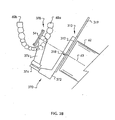
- grip openings 402, 404 permit passage of and connection to connector arm or rod in position 474 or alternatively, position 474'. Openings 402, 404 are preferably sized to provide a tight fit to permit insertion and sliding adjustment of connector arm 474. More preferably, openings 402, 404 each have a molded in tab that is sized to interfere with, but permit sliding of, arm 474, so that it may be adjusted to the proper linear position and remain in place during the x-ray procedure.
- Connector arm 474 is secured at one end to film or digital receptor holding member 478, also known as a basket, by plastic biting portion or bite block 476, which is to be inserted into the patient's mouth, and held by the patient's teeth during the x-ray exposure.
- film or digital receptor holding member 478 also known as a basket
- plastic biting portion or bite block 476 which is to be inserted into the patient's mouth, and held by the patient's teeth during the x-ray exposure.
- the positioning of the receptor holding member and bite block in the patient's mouth is the same as that shown in the previous embodiment of Figs. 17-29 for those that normally use conventional aiming rings.
- a receptor holding member, bite block and securing arm of the embodiments of Figs. 1-16 may be employed with the collimation and shielding device 410 of Figs. 30-32 .
- a removable film or digital-electronic receptor 454 is secured to receptor holding member 478.
- Biting portion 476 may contain elastomeric impression material on opposite biting surfaces that may be used to create teeth impressions and register with the unique occlusion pattern of the patient's teeth, as shown in Figs. 3-8 .
- Arm 474 is preferably non-circular in cross-section, and preferably rectangular as shown, so that collimation shield device 410 does not rotate with respect to the receptor holding member 478.
- a central opening 416 permits passage of x-rays from the x-ray machine's position indicating cylinder device 62 when it is axially aligned with the collimation and shielding device 410.
- the center of opening 416 is coincident with the center of shield 412.
- Central opening 416 as shown is the outermost outline of two intersecting non-square rectangles 416a (shown in portrait orientation) and 416b (shown in landscape orientation) each having side ratios approximately that of the film or detector for the teeth x-ray image.
- the resulting opening is cross-shaped, where the length l of the cross-members is equal to the longer side length of the rectangles 416a, 416b, and the width w of the cross-members is equal to the shorter side length of the rectangles 416a, 416b.
- the cross-shaped opening 416 permits either vertical (portrait) or horizontal (landscape) orientation of a film or electronic receptor.
- This cross-shaped opening also permits the orientation of device 410 to be rotated by 90° if it is desired to change orientation of the handles with respect to the patient's mouth or the x-ray machine, or to change the position of the receptor holding member 478 with respect to the opening 416 in the shield 412.
- the different radial and non-radial orientation of connector arm openings 402, 404 also permits variation of the position of the receptor holding member with respect to openings 416a and 416b for best x-ray view of the desired patient's teeth.
- the openings 416a and 416b may be sized in different l x w increments, such as for standard sizes 0, 1 or 2, or any other size required for a child or adult patient.
- the size and orientation of the receptor holding member is preferably made to match the opening size and orientation of opening 416a or 416b to minimize passage of extraneous and unwanted x-radiation into the patient's mouth.
- the shield of the present invention is still expected to reduce x-ray exposure by about 30-45% compared to prior art aiming rings.
- the shield absorption of this excess radiation also reduces degradation of the image on the x-ray receptor due to secondary scatter of excess radiation in the patient's mouth.
- the present invention provides for improved patient comfort by permitting patient participation in and holding of a collimation plate handle during device positioning and x-ray exposure.
- the different radial and non-radial alignment of multiple handles and arm holders, along with the collimation plate opening that accommodates both vertical and horizontal receptor positioning, permits maximum flexibility and use of the receptor position device for different size patients and different tooth exposures.
Landscapes
- Health & Medical Sciences (AREA)
- Life Sciences & Earth Sciences (AREA)
- Engineering & Computer Science (AREA)
- Medical Informatics (AREA)
- General Health & Medical Sciences (AREA)
- Physics & Mathematics (AREA)
- Nuclear Medicine, Radiotherapy & Molecular Imaging (AREA)
- Heart & Thoracic Surgery (AREA)
- High Energy & Nuclear Physics (AREA)
- Veterinary Medicine (AREA)
- Oral & Maxillofacial Surgery (AREA)
- Optics & Photonics (AREA)
- Pathology (AREA)
- Radiology & Medical Imaging (AREA)
- Biomedical Technology (AREA)
- Biophysics (AREA)
- Molecular Biology (AREA)
- Surgery (AREA)
- Animal Behavior & Ethology (AREA)
- Public Health (AREA)
- General Physics & Mathematics (AREA)
- Dentistry (AREA)
- Apparatus For Radiation Diagnosis (AREA)
Claims (7)
- Rezeptor-Positionierungsvorrichtung (410) zum Aufnehmen von zahnärztlichen Bissflügel-Röntgenbildern der Zähne eines Patienten, die Folgendes umfasst:ein Rezeptor-Halteelement (478), das dafür eingerichtet ist, einen Rezeptor (494) zum Belichten mit Röntgenstrahlung aus einem Röntgengerät aufzunehmen, undeinen Arm (474, 474'), der an dem Rezeptor-Halteelement befestigt ist und eine Beißfläche (476) zum In-Eingriff-Nehmen der Zähne (60a) eines Patienten einschließt, um die Vorrichtung im Mund des Patienten zu befestigen,gekennzeichnet durch:eine Kollimationsplatte (412), die eine Öffnung (416) für einen Durchgang von Strahlung aus dem Röntgengerät hat und die wenigstens teilweise in der Form einem Rezeptor (454) in dem Rezeptor-Halteelement (478) entspricht, wobei die Kollimationsplatte (412) eine im Wesentlichen ebene Fläche um die Öffnung (416) zum Ausrichten mit dem Röntgengerät und hergestellt aus einem Werkstoff und ausreichend bemessen, um eine unerwünschte Strahlung aus dem Mund des Patienten zu dämpfen, undein Paar von Handgriffen (418, 419), die sich weg von der Plattenfläche erstrecken, zum Ergreifen durch den Patienten, um die Vorrichtung (410) zu positionieren, wobei die Kollimationsplatte (412) einen verstärkten Armhalter (401, 403) angrenzend an die Plattenfläche an der Basis jedes Griffs einschließt, der eine Öffnung (402, 404) in demselben hat, um den Arm (474, 474') verschiebbar aufzunehmen und die Kollimationsplatte (412) abnehmbar an dem Arm und dem Rezeptor-Halteelement (478) zu befestigen.
- Vorrichtung nach Anspruch 1, wobei die Kollimationsplatte (412) aus einem Metall hergestellt ist und ferner Polymergriffe (518, 519) an den Handgriffen einschließt, die den Armhalter einschließen, wobei die Kollimationsplatte einen ausgeschnittenen Abschnitt (405, 406) angrenzend an eine Basis des Handgriffs hat, durch den sich die Armaufnahmeöffnung (402, 404) des Polymer-Armhalters erstreckt.
- Vorrichtung nach Anspruch 1, wobei die Armaufnahmeöffnung (402, 404) des Armhalters (401, 403) rechteckig ist und die Kollimationsplatte (412) einen ausgeschnittenen Abschnitt (405, 406) angrenzend an eine Basis des Handgriffs (418, 419) auf wenigstens zwei Seiten der rechteckigen Armaufnahmeöffnung hat.
- Vorrichtung nach Anspruch 3, wobei die eine der rechteckigen Armaufnahmeöffnungen (402) in Radialrichtung mit der Kollimationsplattenöffnung (416) ausgerichtet ist und die andere der rechteckigen Armaufnahmeöffnungen (404) nicht in Radialrichtung mit der Kollimationsplattenöffnung ausgerichtet ist.
- Vorrichtung nach Anspruch 1 oder Anspruch 3, wobei jeder Handgriff einen Polymerabschnitt (518, 519) mit einer rechteckigen Armaufnahmeöffnung hat, wobei der eine der Handgriffe (419) in Radialrichtung mit der Kollimationsplattenöffnung (416) ausgerichtet ist und der andere der Handgriffe (418) nicht in Radialrichtung mit der Kollimationsplattenöffnung ausgerichtet ist.
- Vorrichtung nach Anspruch 1, wobei die Kollimationsplatte (412) aus einer Verbindung mit hoher Schwere hergestellt ist, wobei die Kollimationsplatte einen ausgeschnittenen Abschnitt (405, 406) angrenzend an eine Basis des Handgriffs (418, 419) hat, durch den sich die Armaufnahmeöffnung (402, 404) des Armhalters erstreckt.
- Vorrichtung nach einem der vorhergehenden Ansprüche, wobei die Öffnung (416) eine kreuzförmige Überschneidung von zwei nicht-quadratischen Rechtecken (416a, 416b) ist, die Glieder mit einer Länge (1) und einer Breite (w) hat, wobei die Länge der Kreuzglieder gleich einer längeren Seitenlänge der Rechtecke ist und die Breite der Kreuzglieder gleich einer kürzeren Seitenlänge der Rechtecke ist.
Applications Claiming Priority (2)
| Application Number | Priority Date | Filing Date | Title |
|---|---|---|---|
| US11/559,628 US7427159B2 (en) | 2004-07-26 | 2006-11-14 | Intraoral dental radiology positioning device for use with x-ray receptor |
| PCT/US2007/022738 WO2008060395A2 (en) | 2006-11-14 | 2007-10-24 | Intraoral dental radiology positioning device for use with x-ray receptor |
Publications (3)
| Publication Number | Publication Date |
|---|---|
| EP2083697A2 EP2083697A2 (de) | 2009-08-05 |
| EP2083697A4 EP2083697A4 (de) | 2009-12-16 |
| EP2083697B1 true EP2083697B1 (de) | 2013-05-22 |
Family
ID=39402181
Family Applications (1)
| Application Number | Title | Priority Date | Filing Date |
|---|---|---|---|
| EP07839804.7A Not-in-force EP2083697B1 (de) | 2006-11-14 | 2007-10-24 | Intraorale dentale radiologie-positionierungsvorrichtung zur verwendung mit einem röntgenrezeptor |
Country Status (3)
| Country | Link |
|---|---|
| US (1) | US7427159B2 (de) |
| EP (1) | EP2083697B1 (de) |
| WO (1) | WO2008060395A2 (de) |
Families Citing this family (9)
| Publication number | Priority date | Publication date | Assignee | Title |
|---|---|---|---|---|
| US20110299663A1 (en) * | 2009-05-27 | 2011-12-08 | Steward Jr Curtis L | Universal dental x-ray sensor holder with elastomeric clamping vise |
| CA2764380C (en) | 2009-06-10 | 2018-10-02 | Valerie Archibald | Alignment device for bitewing radiograph |
| US9314215B2 (en) * | 2012-08-22 | 2016-04-19 | Sirona Dental, Inc. | Dental positioning system |
| USD698442S1 (en) | 2013-05-30 | 2014-01-28 | Dentsply International Inc. | Holder for a digital dental x-ray sensor |
| USD755972S1 (en) | 2013-12-12 | 2016-05-10 | Dentsply International Inc. | Holder for digital dental X-ray sensor |
| US20150230764A1 (en) * | 2014-02-19 | 2015-08-20 | Dental Imaging Technologies Corporation | Dose-reducing x-ray aiming device |
| KR20150134629A (ko) * | 2014-05-22 | 2015-12-02 | 주식회사바텍 | 센서 일체형 방사선 차폐장치 |
| US20180014799A1 (en) * | 2016-07-18 | 2018-01-18 | Harold K. Schmulenson | System configured to hold a radiation sensing device in a variety of positions |
| EP3827751B1 (de) | 2019-11-28 | 2022-06-08 | SIRONA Dental Systems GmbH | Verfahren zur optimalen positionierung während der intraoralen bildgebung |
Family Cites Families (20)
| Publication number | Priority date | Publication date | Assignee | Title |
|---|---|---|---|---|
| USRE25773E (en) * | 1965-05-04 | Ray film holder and aiming element | ||
| US2034049A (en) * | 1936-03-17 | Indicative apparatus for obtaining | ||
| US3092721A (en) * | 1961-07-28 | 1963-06-04 | Fred M Medwedeff | X-ray film holder and aiming element |
| US3304422A (en) * | 1964-07-30 | 1967-02-14 | Prec X Ray Company | Dental X-ray shield and film holding support having a bite-receiving member |
| US3304423A (en) * | 1966-03-25 | 1967-02-14 | Fred M Medwedeff | Dental X-ray shield and aiming means and film holder means mounted on opposite ends of bite means |
| US3745344A (en) * | 1971-12-20 | 1973-07-10 | W Updegrave | Intradral radiographic system for substantially confining the x-ray beam to the film |
| SE453047B (sv) * | 1981-11-04 | 1988-01-11 | Trollhetteplast Forseljnings A | Hjelpmedel for utforande av tandrontgenundersokningar |
| USD281353S (en) * | 1983-02-07 | 1985-11-12 | Rinn Corporation | Collimator for dental x-ray instrument aiming rings |
| USD283157S (en) * | 1983-03-16 | 1986-03-25 | The S. S. White Company | Device for positioning dental x-ray film |
| US4554676A (en) * | 1983-03-16 | 1985-11-19 | The S. S. White Company | Dental aiming device |
| US5090047A (en) * | 1990-10-23 | 1992-02-18 | Applied Research Company | Apparatus for reproducibly positioning an image receptor for intraoral diagnostics |
| US5327477A (en) * | 1992-12-29 | 1994-07-05 | Paul Levy | Film positioning system for dental X-ray procedures |
| US5629972A (en) * | 1993-05-18 | 1997-05-13 | Research Foundation Of State University Of New York | Intraoral radiograph alignment device |
| US5416822A (en) * | 1994-08-29 | 1995-05-16 | Kunik; Randall L. | Device for registering a dental radiograph having distortion measuring capability and method for using the same |
| US5625666A (en) * | 1995-11-29 | 1997-04-29 | Willis; Timothy G. | Radiographic film retaining device |
| US6343875B1 (en) * | 1999-06-30 | 2002-02-05 | Dentsply Research & Development Corp. | Modular bite block and sensor holder apparatus for dental x-ray procedures |
| US6599013B1 (en) * | 2002-04-01 | 2003-07-29 | Jennifer A. Diederich | Intraoral dental radiology positioning device |
| US7056015B2 (en) * | 2002-04-01 | 2006-06-06 | Diederich Jennifer A | Intraoral dental radiology positioning device |
| US7033075B2 (en) * | 2002-11-27 | 2006-04-25 | Op-D-Op, Inc. | Apparatus for retaining a radiographic sensor during dental x-ray imaging |
| US7172339B2 (en) * | 2004-07-26 | 2007-02-06 | Jennifer A Diederich | Intraoral dental radiology positioning device for use with aiming ring |
-
2006
- 2006-11-14 US US11/559,628 patent/US7427159B2/en not_active Expired - Fee Related
-
2007
- 2007-10-24 WO PCT/US2007/022738 patent/WO2008060395A2/en not_active Ceased
- 2007-10-24 EP EP07839804.7A patent/EP2083697B1/de not_active Not-in-force
Also Published As
| Publication number | Publication date |
|---|---|
| US20080025467A1 (en) | 2008-01-31 |
| US7427159B2 (en) | 2008-09-23 |
| WO2008060395A2 (en) | 2008-05-22 |
| WO2008060395A3 (en) | 2008-12-18 |
| EP2083697A4 (de) | 2009-12-16 |
| EP2083697A2 (de) | 2009-08-05 |
Similar Documents
| Publication | Publication Date | Title |
|---|---|---|
| EP2083697B1 (de) | Intraorale dentale radiologie-positionierungsvorrichtung zur verwendung mit einem röntgenrezeptor | |
| US5001738A (en) | Dental X-ray film holding tab and alignment method | |
| US7172339B2 (en) | Intraoral dental radiology positioning device for use with aiming ring | |
| US5327477A (en) | Film positioning system for dental X-ray procedures | |
| US7056015B2 (en) | Intraoral dental radiology positioning device | |
| US7097356B2 (en) | Radiographic sensor positioning system | |
| EP1194811B1 (de) | Positioniervorrichtung für verschiedene dentale Röntgenaufnahmeverfahren mit einer Sensorhalterung und unterschiedlichen Bi blöcken modularen Designs | |
| EP2887877B1 (de) | Dental positioniersytem | |
| US6190042B1 (en) | Dental x-ray aiming device for longitudinal radiographic analysis | |
| US7036985B2 (en) | X-ray positioning device | |
| US5119410A (en) | Rotating poisitioning instrument for intra oral radiography | |
| US20090168953A1 (en) | Dental x-ray bite block and alignment method | |
| US9498170B2 (en) | Apparatus for holding and positioning X-ray film, photostimulable phosphor plates or digital sensors while taking dental radiographs | |
| US20030185347A1 (en) | Intraoral dental radiology positioning device | |
| KR100920848B1 (ko) | 구강 내 방사선 촬영을 위한 각도 지시 필름 홀더 및 필름 지지부 | |
| US20180279976A1 (en) | Intraoral sensor positioning system | |
| US6599013B1 (en) | Intraoral dental radiology positioning device | |
| JP2012501212A (ja) | 歯科x線処置の位置決め装置 | |
| EP2440138B1 (de) | Ausrichtungsvorrichtung für eine flügelbissröntgenaufnahme | |
| US20230251562A1 (en) | X-ray holder | |
| WO1981002973A1 (en) | X-ray film holder for use in making dental radiographs | |
| RU61535U1 (ru) | Дентальный аппарат | |
| Sewerin | Modified Eggen equipment for dental X-ray machines with a non-removable open-ended cone | |
| Kihara et al. | A device for the reduction of population dose |
Legal Events
| Date | Code | Title | Description |
|---|---|---|---|
| PUAI | Public reference made under article 153(3) epc to a published international application that has entered the european phase |
Free format text: ORIGINAL CODE: 0009012 |
|
| 17P | Request for examination filed |
Effective date: 20090608 |
|
| AK | Designated contracting states |
Kind code of ref document: A2 Designated state(s): AT BE BG CH CY CZ DE DK EE ES FI FR GB GR HU IE IS IT LI LT LU LV MC MT NL PL PT RO SE SI SK TR |
|
| A4 | Supplementary search report drawn up and despatched |
Effective date: 20091117 |
|
| DAX | Request for extension of the european patent (deleted) | ||
| 17Q | First examination report despatched |
Effective date: 20100309 |
|
| RIC1 | Information provided on ipc code assigned before grant |
Ipc: G03B 42/04 20060101ALN20121002BHEP Ipc: A61B 6/14 20060101AFI20121002BHEP |
|
| GRAP | Despatch of communication of intention to grant a patent |
Free format text: ORIGINAL CODE: EPIDOSNIGR1 |
|
| RIC1 | Information provided on ipc code assigned before grant |
Ipc: A61B 6/14 20060101AFI20121109BHEP Ipc: G03B 42/04 20060101ALN20121109BHEP |
|
| GRAS | Grant fee paid |
Free format text: ORIGINAL CODE: EPIDOSNIGR3 |
|
| GRAA | (expected) grant |
Free format text: ORIGINAL CODE: 0009210 |
|
| AK | Designated contracting states |
Kind code of ref document: B1 Designated state(s): AT BE BG CH CY CZ DE DK EE ES FI FR GB GR HU IE IS IT LI LT LU LV MC MT NL PL PT RO SE SI SK TR |
|
| REG | Reference to a national code |
Ref country code: GB Ref legal event code: FG4D |
|
| REG | Reference to a national code |
Ref country code: CH Ref legal event code: EP |
|
| REG | Reference to a national code |
Ref country code: AT Ref legal event code: REF Ref document number: 612756 Country of ref document: AT Kind code of ref document: T Effective date: 20130615 |
|
| REG | Reference to a national code |
Ref country code: IE Ref legal event code: FG4D |
|
| REG | Reference to a national code |
Ref country code: DE Ref legal event code: R096 Ref document number: 602007030679 Country of ref document: DE Effective date: 20130718 |
|
| REG | Reference to a national code |
Ref country code: SE Ref legal event code: TRGR |
|
| REG | Reference to a national code |
Ref country code: NL Ref legal event code: T3 |
|
| REG | Reference to a national code |
Ref country code: AT Ref legal event code: MK05 Ref document number: 612756 Country of ref document: AT Kind code of ref document: T Effective date: 20130522 |
|
| REG | Reference to a national code |
Ref country code: LT Ref legal event code: MG4D |
|
| PG25 | Lapsed in a contracting state [announced via postgrant information from national office to epo] |
Ref country code: ES Free format text: LAPSE BECAUSE OF FAILURE TO SUBMIT A TRANSLATION OF THE DESCRIPTION OR TO PAY THE FEE WITHIN THE PRESCRIBED TIME-LIMIT Effective date: 20130902 Ref country code: AT Free format text: LAPSE BECAUSE OF FAILURE TO SUBMIT A TRANSLATION OF THE DESCRIPTION OR TO PAY THE FEE WITHIN THE PRESCRIBED TIME-LIMIT Effective date: 20130522 Ref country code: IS Free format text: LAPSE BECAUSE OF FAILURE TO SUBMIT A TRANSLATION OF THE DESCRIPTION OR TO PAY THE FEE WITHIN THE PRESCRIBED TIME-LIMIT Effective date: 20130922 Ref country code: LT Free format text: LAPSE BECAUSE OF FAILURE TO SUBMIT A TRANSLATION OF THE DESCRIPTION OR TO PAY THE FEE WITHIN THE PRESCRIBED TIME-LIMIT Effective date: 20130522 Ref country code: SI Free format text: LAPSE BECAUSE OF FAILURE TO SUBMIT A TRANSLATION OF THE DESCRIPTION OR TO PAY THE FEE WITHIN THE PRESCRIBED TIME-LIMIT Effective date: 20130522 Ref country code: FI Free format text: LAPSE BECAUSE OF FAILURE TO SUBMIT A TRANSLATION OF THE DESCRIPTION OR TO PAY THE FEE WITHIN THE PRESCRIBED TIME-LIMIT Effective date: 20130522 Ref country code: GR Free format text: LAPSE BECAUSE OF FAILURE TO SUBMIT A TRANSLATION OF THE DESCRIPTION OR TO PAY THE FEE WITHIN THE PRESCRIBED TIME-LIMIT Effective date: 20130823 Ref country code: PT Free format text: LAPSE BECAUSE OF FAILURE TO SUBMIT A TRANSLATION OF THE DESCRIPTION OR TO PAY THE FEE WITHIN THE PRESCRIBED TIME-LIMIT Effective date: 20130923 |
|
| PG25 | Lapsed in a contracting state [announced via postgrant information from national office to epo] |
Ref country code: PL Free format text: LAPSE BECAUSE OF FAILURE TO SUBMIT A TRANSLATION OF THE DESCRIPTION OR TO PAY THE FEE WITHIN THE PRESCRIBED TIME-LIMIT Effective date: 20130522 Ref country code: BG Free format text: LAPSE BECAUSE OF FAILURE TO SUBMIT A TRANSLATION OF THE DESCRIPTION OR TO PAY THE FEE WITHIN THE PRESCRIBED TIME-LIMIT Effective date: 20130822 |
|
| PG25 | Lapsed in a contracting state [announced via postgrant information from national office to epo] |
Ref country code: LV Free format text: LAPSE BECAUSE OF FAILURE TO SUBMIT A TRANSLATION OF THE DESCRIPTION OR TO PAY THE FEE WITHIN THE PRESCRIBED TIME-LIMIT Effective date: 20130522 |
|
| PG25 | Lapsed in a contracting state [announced via postgrant information from national office to epo] |
Ref country code: CZ Free format text: LAPSE BECAUSE OF FAILURE TO SUBMIT A TRANSLATION OF THE DESCRIPTION OR TO PAY THE FEE WITHIN THE PRESCRIBED TIME-LIMIT Effective date: 20130522 Ref country code: EE Free format text: LAPSE BECAUSE OF FAILURE TO SUBMIT A TRANSLATION OF THE DESCRIPTION OR TO PAY THE FEE WITHIN THE PRESCRIBED TIME-LIMIT Effective date: 20130522 Ref country code: BE Free format text: LAPSE BECAUSE OF FAILURE TO SUBMIT A TRANSLATION OF THE DESCRIPTION OR TO PAY THE FEE WITHIN THE PRESCRIBED TIME-LIMIT Effective date: 20130522 Ref country code: SK Free format text: LAPSE BECAUSE OF FAILURE TO SUBMIT A TRANSLATION OF THE DESCRIPTION OR TO PAY THE FEE WITHIN THE PRESCRIBED TIME-LIMIT Effective date: 20130522 Ref country code: DK Free format text: LAPSE BECAUSE OF FAILURE TO SUBMIT A TRANSLATION OF THE DESCRIPTION OR TO PAY THE FEE WITHIN THE PRESCRIBED TIME-LIMIT Effective date: 20130522 |
|
| PG25 | Lapsed in a contracting state [announced via postgrant information from national office to epo] |
Ref country code: RO Free format text: LAPSE BECAUSE OF FAILURE TO SUBMIT A TRANSLATION OF THE DESCRIPTION OR TO PAY THE FEE WITHIN THE PRESCRIBED TIME-LIMIT Effective date: 20130522 Ref country code: IT Free format text: LAPSE BECAUSE OF FAILURE TO SUBMIT A TRANSLATION OF THE DESCRIPTION OR TO PAY THE FEE WITHIN THE PRESCRIBED TIME-LIMIT Effective date: 20130522 |
|
| PLBE | No opposition filed within time limit |
Free format text: ORIGINAL CODE: 0009261 |
|
| STAA | Information on the status of an ep patent application or granted ep patent |
Free format text: STATUS: NO OPPOSITION FILED WITHIN TIME LIMIT |
|
| 26N | No opposition filed |
Effective date: 20140225 |
|
| PG25 | Lapsed in a contracting state [announced via postgrant information from national office to epo] |
Ref country code: MC Free format text: LAPSE BECAUSE OF FAILURE TO SUBMIT A TRANSLATION OF THE DESCRIPTION OR TO PAY THE FEE WITHIN THE PRESCRIBED TIME-LIMIT Effective date: 20130522 |
|
| REG | Reference to a national code |
Ref country code: CH Ref legal event code: PL |
|
| REG | Reference to a national code |
Ref country code: DE Ref legal event code: R097 Ref document number: 602007030679 Country of ref document: DE Effective date: 20140225 |
|
| GBPC | Gb: european patent ceased through non-payment of renewal fee |
Effective date: 20131024 |
|
| REG | Reference to a national code |
Ref country code: IE Ref legal event code: MM4A |
|
| PG25 | Lapsed in a contracting state [announced via postgrant information from national office to epo] |
Ref country code: GB Free format text: LAPSE BECAUSE OF NON-PAYMENT OF DUE FEES Effective date: 20131024 Ref country code: CH Free format text: LAPSE BECAUSE OF NON-PAYMENT OF DUE FEES Effective date: 20131031 Ref country code: LI Free format text: LAPSE BECAUSE OF NON-PAYMENT OF DUE FEES Effective date: 20131031 |
|
| REG | Reference to a national code |
Ref country code: FR Ref legal event code: ST Effective date: 20140630 |
|
| PG25 | Lapsed in a contracting state [announced via postgrant information from national office to epo] |
Ref country code: FR Free format text: LAPSE BECAUSE OF NON-PAYMENT OF DUE FEES Effective date: 20131031 |
|
| PG25 | Lapsed in a contracting state [announced via postgrant information from national office to epo] |
Ref country code: IE Free format text: LAPSE BECAUSE OF NON-PAYMENT OF DUE FEES Effective date: 20131024 |
|
| PG25 | Lapsed in a contracting state [announced via postgrant information from national office to epo] |
Ref country code: CY Free format text: LAPSE BECAUSE OF FAILURE TO SUBMIT A TRANSLATION OF THE DESCRIPTION OR TO PAY THE FEE WITHIN THE PRESCRIBED TIME-LIMIT Effective date: 20130522 Ref country code: TR Free format text: LAPSE BECAUSE OF FAILURE TO SUBMIT A TRANSLATION OF THE DESCRIPTION OR TO PAY THE FEE WITHIN THE PRESCRIBED TIME-LIMIT Effective date: 20130522 |
|
| PG25 | Lapsed in a contracting state [announced via postgrant information from national office to epo] |
Ref country code: HU Free format text: LAPSE BECAUSE OF FAILURE TO SUBMIT A TRANSLATION OF THE DESCRIPTION OR TO PAY THE FEE WITHIN THE PRESCRIBED TIME-LIMIT; INVALID AB INITIO Effective date: 20071024 Ref country code: LU Free format text: LAPSE BECAUSE OF NON-PAYMENT OF DUE FEES Effective date: 20131024 |
|
| PG25 | Lapsed in a contracting state [announced via postgrant information from national office to epo] |
Ref country code: MT Free format text: LAPSE BECAUSE OF FAILURE TO SUBMIT A TRANSLATION OF THE DESCRIPTION OR TO PAY THE FEE WITHIN THE PRESCRIBED TIME-LIMIT Effective date: 20130522 |
|
| PGFP | Annual fee paid to national office [announced via postgrant information from national office to epo] |
Ref country code: DE Payment date: 20191008 Year of fee payment: 13 Ref country code: SE Payment date: 20191010 Year of fee payment: 13 Ref country code: NL Payment date: 20191014 Year of fee payment: 13 |
|
| REG | Reference to a national code |
Ref country code: DE Ref legal event code: R119 Ref document number: 602007030679 Country of ref document: DE |
|
| REG | Reference to a national code |
Ref country code: SE Ref legal event code: EUG |
|
| REG | Reference to a national code |
Ref country code: NL Ref legal event code: MM Effective date: 20201101 |
|
| PG25 | Lapsed in a contracting state [announced via postgrant information from national office to epo] |
Ref country code: DE Free format text: LAPSE BECAUSE OF NON-PAYMENT OF DUE FEES Effective date: 20210501 Ref country code: NL Free format text: LAPSE BECAUSE OF NON-PAYMENT OF DUE FEES Effective date: 20201101 |
|
| PG25 | Lapsed in a contracting state [announced via postgrant information from national office to epo] |
Ref country code: SE Free format text: LAPSE BECAUSE OF NON-PAYMENT OF DUE FEES Effective date: 20201025 |