EP2084355B1 - Schloss für eine tragbare vorrichtung - Google Patents
Schloss für eine tragbare vorrichtung Download PDFInfo
- Publication number
- EP2084355B1 EP2084355B1 EP07822124A EP07822124A EP2084355B1 EP 2084355 B1 EP2084355 B1 EP 2084355B1 EP 07822124 A EP07822124 A EP 07822124A EP 07822124 A EP07822124 A EP 07822124A EP 2084355 B1 EP2084355 B1 EP 2084355B1
- Authority
- EP
- European Patent Office
- Prior art keywords
- docking station
- sensor
- message
- station according
- software unit
- Prior art date
- Legal status (The legal status is an assumption and is not a legal conclusion. Google has not performed a legal analysis and makes no representation as to the accuracy of the status listed.)
- Not-in-force
Links
Images


Classifications
-
- E—FIXED CONSTRUCTIONS
- E05—LOCKS; KEYS; WINDOW OR DOOR FITTINGS; SAFES
- E05B—LOCKS; ACCESSORIES THEREFOR; HANDCUFFS
- E05B73/00—Devices for locking portable objects against unauthorised removal; Miscellaneous locking devices
-
- A—HUMAN NECESSITIES
- A61—MEDICAL OR VETERINARY SCIENCE; HYGIENE
- A61B—DIAGNOSIS; SURGERY; IDENTIFICATION
- A61B6/00—Apparatus or devices for radiation diagnosis; Apparatus or devices for radiation diagnosis combined with radiation therapy equipment
- A61B6/44—Constructional features of apparatus for radiation diagnosis
- A61B6/4405—Constructional features of apparatus for radiation diagnosis the apparatus being movable or portable, e.g. handheld or mounted on a trolley
-
- G—PHYSICS
- G06—COMPUTING OR CALCULATING; COUNTING
- G06F—ELECTRIC DIGITAL DATA PROCESSING
- G06F1/00—Details not covered by groups G06F3/00 - G06F13/00 and G06F21/00
- G06F1/16—Constructional details or arrangements
- G06F1/1613—Constructional details or arrangements for portable computers
- G06F1/1632—External expansion units, e.g. docking stations
Definitions
- the present invention relates to a docking station, according to the preamble of claim 1.
- the patent application DE10202330 discloses a locking system for the doors of a motor vehicle using an electric lock release control from an electric signal.
- An object of the invention is in particular to overcome the aforementioned drawbacks.
- the subject of the invention is a docking station for portable X-ray sensor equipment according to claim 1.
- the deactivated state of the electrical signal can be carried out from an inhibition message sent by the software unit to the host equipment.
- the inhibition message can produce a signal, amplified by a suitable interface.
- the amplified signal opens a supply circuit of the electromechanical system.
- Disinhibition of the electrical signal can be achieved from a disinhibition message sent by the software unit to the host equipment.
- the disinhibition message produces a signal amplified by a suitable interface.
- the amplified signal closes the supply circuit of the electromechanical system.
- Entering a password via the software unit may cause the disabling message to be sent by the software unit. Entering a password secures the use of the portable equipment.
- the sending of the inhibition message can be carried out automatically by the software unit while respecting a parameterizable time criterion.
- the electromechanical system may comprise at least one electromagnet acting on a magnet connected to the fixing means and allowing the fastening means to open.
- the electrical signal is produced for example by a button on the host equipment.
- the electromechanical system may comprise a mechanical release means.
- the software unit may be a computer, including a medical imaging system management software, connected to the docking station by a link.
- the main advantages of the invention are that it is simple to use and to implement as well as inexpensive to produce.
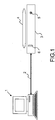
- the figure 1 represents a medical imaging system.
- This system comprises a software unit 1 for managing the medical imaging system.
- This software unit 1 may be a computer 1 comprising a management software of the medical imaging system.
- the computer 1 communicates via a link 2 with a docking station 3 for a sensor 4.
- the link 2 between the docking station 3 and the computer 1 may be a wired or optical link or any other type of link allowing data exchange between two electronic devices.
- the docking station 3 may for example be a battery recharging station of the sensor 4 also serving the communication relay sensor 4 to the computer 1 for managing the medical imaging system.
- the sensor 4 at rest is thus placed on the docking station 3.
- the docking station 3 has a device for fixing the sensor 4 when it is placed in contact with it.
- This fixing device is associated with a device according to the invention for blocking and unblocking the sensor 4 when it is placed on the docking station 3.
- the unlocking of the sensor 4 can be done either with the aid of a side button 5, which can be a push button, or with a key to be inserted in a lock 6 positioned on the docking station 3.
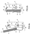
- the Figures 2a and 2b represent an example of a device for fixing the sensor 4 on the docking station 3.
- the figure 2a represents the sensor 4 in an unlocked position with respect to the docking station 3.
- the figure 2b represents the sensor 4 blocked on the docking station 3.
- the sensor 4, on the Figures 2a and 2b is in the form of a small suitcase, having a first end 31 and a second end 32, which is placed on the docking station 3.
- the docking station 3, represented in the form of a rectangular block, is provided with a fixing device 20 for holding the sensor 4 when the latter is placed on the docking station 3.
- the fixing device 20 of the sensor 4 on the docking station 3 is, in the frame of the device according to the invention, blocked when the sensor 4 is placed on the docking station 3 so that the sensor 4 can not be removed from the docking station 3 without performing a specific unlocking procedure.
- a button 5, positioned for example on the lateral part of the docking station 3, can be used to release the sensor 4 by a simple pressure. This pressure makes it possible to actuate the fixing device 20 so that it releases the sensor 4.
- the button 5 can be placed in a non-obvious manner so that only the personnel having knowledge of its existence can actuate it. This reduces the number of people able to remove the sensor 4 from the docking station 3.
- the fixing device 20 of the sensor 4 on the docking station 3 may comprise two rigid blades 21, 22 for holding the sensor 4 is in contact with the docking station 3.
- the sensor 4 is slid between the first blade 21 and the docking station 3 in order to be tackled on the docking station 3.
- the first blade 21 is secured to the station 3.
- the sensor 4 exerts a pressure on a first rod 23 connected to a second rod 24 by a first axis
- the rotational movement of the first rod 23 causes a translation of the second rod 24.
- a magnet 25 is mounted on the second rod 24.
- the magnet 26 When the fixing device 20 of the sensor 4 is in an open position as shown on the figure 2a the magnet 26 is positioned between two electromagnets 27, 28. When the fastener 20 of the sensor 4 closes, the magnet 26 is translated in translation by the second rod 24: it is no longer positioned between the two electromagnets 27, 28.
- the second rod 24, during the closure of the fixing device 20 of the sensor 4 causes in its translational movement a second movable axis of rotation 29 integral with the second rod 24 and the second blade 22.
- the translation of the second rod 24 will cause, through the second axis of rotation 29, a rotation of the second blade 22 around a third axis of rotation 30 integral with the docking station 3.
- the second blade 22 then will come to cap the second end 32 of the sensor 4, thereby blocking the sensor 4 on the docking station 3.
- the fixing device 20 advantageously allows the sensor 4 to be locked automatically when it is deposited on the docking station 3.
- the grip of the sensor 4 requires a simple manual operation which may consist of pressing the button 5 then removing the sensor 4 from the fastener 20 open by pressing the button 5.
- the figure 3 shows an implementation of an electromechanical device 48 according to the invention for blocking and unblocking the sensor 4 when it is positioned on the docking station 3, blocked by the fixing device 20 of the sensor 4.
- the device 48 blocking and unlocking according to the invention may for example comprise a power supply 40 for supplying the electromagnets 27, 28 when the supply circuit 41 is closed.
- the supply circuit 41 has for example two switches 42, 43.
- the first switch 42 closes on a button 5 which generates an electric signal 44 for this purpose. Closing the first switch 42 causes a power supply of the two electromagnets 27, 28, thus unlocking the sensor 4 as shown in FIG. figure 2a .
- the unlocking of the sensor produced by means of the button 5 is therefore an electric release.
- the second switch 43 is open only when an inhibition of electromagnetic deblocking has been requested.
- the inhibition of the unlocking of the sensor 4, using the button 5, can be achieved by means of an inhibition message 45 sent from the computer 1 to the station 3. Once this inhibition message 45 has been received by the docking station 3, a suitable interface 46 converts this message into an amplified signal 51 transmitted to a control box 47 which opens the switch 43. In this case, pressing the button 5 has no effect on the unlocking of the sensor 4 and this as long as a disinhibition message 49 has not been sent by the computer 1.
- the interface 46 transforms this disinhibition message 49 into an amplified signal 51 transmitted to the control unit 47 so that it closes the switch 43. Once the switch 43 closed, a simple press of the button 5 allows to unlock the sensor 4.
- the inhibition message 45 may be sent by a user via a human machine interface of the medical imaging system management software.
- the inhibition message 45 can also be sent automatically by the management software of the medical imaging system on a parameterizable criterion in the management software of the medical imaging system.
- This criterion may be, for example, a time criterion such as a time and a start date of the inhibition or a determined time since the last use of the sensor 4.
- the operation of the inhibition in automatic or manual mode can be set in the management software of the medical imaging system.
- the disinhibition message 49 may be sent on an action of the user from the management software of the medical imaging system or by entering a password for example. This makes it possible to secure the use of the portable equipment: only those with knowledge of the management software of the medical imaging system or even the password can uninhibit the unlocking of the sensor 4.
- a mechanical means 50 of unlocking allows for example by means of a key, to play in the lock 6 of the docking station 3, to release the sensor 4 from the station 3.
- the key can act for example by driving a not shown mechanical system that pulls the rod 24 to position the magnet 26 between the two electromagnets 27, 28, resulting in the unlocking of the sensor 4 as shown in FIG. figure 2a . This therefore advantageously makes it possible to unlock the sensor 4 when the link 2 between the computer and the docking station 3 does not work or the password of the computer has been lost for example.
- the device according to the invention thus makes it possible to have several means for locking and unlocking the sensor 4 according to different use cases.
- the main advantage of the station according to the invention is that there is no sharing of keys between different users but only a shared use of the medical imaging equipment management system. existing independently of the anti-theft protection.
- Another advantage of the station according to the invention is that in standard use it is not necessary to enter a code or even to have a key for each use of the sensor 4. This is advantageous for example during a intensive use of the sensor 4: the maneuvers to be performed to unlock the sensor 4 are then fast and simple.
- the locking of the sensor is advantageously by simply placing the sensor 4 on the docking station 3, without further manipulation. This makes it possible to guarantee the blocking of the sensor 3 as soon as it is placed on the docking station 3.
- Another advantage of the invention is that it is simple to implement. Indeed, the invention requires little addition to the existing hardware.
Landscapes
- Engineering & Computer Science (AREA)
- Life Sciences & Earth Sciences (AREA)
- Health & Medical Sciences (AREA)
- Theoretical Computer Science (AREA)
- Medical Informatics (AREA)
- Physics & Mathematics (AREA)
- Pathology (AREA)
- Heart & Thoracic Surgery (AREA)
- General Engineering & Computer Science (AREA)
- Biophysics (AREA)
- High Energy & Nuclear Physics (AREA)
- Human Computer Interaction (AREA)
- Nuclear Medicine, Radiotherapy & Molecular Imaging (AREA)
- Optics & Photonics (AREA)
- Computer Hardware Design (AREA)
- Radiology & Medical Imaging (AREA)
- Biomedical Technology (AREA)
- General Physics & Mathematics (AREA)
- Molecular Biology (AREA)
- Surgery (AREA)
- Animal Behavior & Ethology (AREA)
- General Health & Medical Sciences (AREA)
- Public Health (AREA)
- Veterinary Medicine (AREA)
- Apparatus For Radiation Diagnosis (AREA)
- Burglar Alarm Systems (AREA)
- Lock And Its Accessories (AREA)
- Fittings On The Vehicle Exterior For Carrying Loads, And Devices For Holding Or Mounting Articles (AREA)
- Telephone Function (AREA)
Claims (9)
- Dockingstation für ein tragbares Röntgensensorgerät (4), wobei der Röntgensensor (4) für den Kontakt mit der Dockingstation (3) ausgelegt ist, umfassend Mittel (20) zum Andocken des tragbaren Röntgensensorgerätes (4) an der Dockingstation (3), wobei die Dockingstation ein elektromechanisches System (48) umfasst, das das Entsperren des Andockmittels (20) mit einem elektrischen Signal (44) steuert, dadurch gekennzeichnet, dass das elektrische Signal (44) durch einen Befehl (45) gesperrt wird, der von einer Softwareeinheit (1) gegeben wird.
- Dockingstation nach Anspruch 1, dadurch gekennzeichnet, dass das elektrische Signal (44) durch eine Sperrmeldung (45) gesperrt wird, die von der Softwareeinheit (1) zur Dockingstation (3) gesendet wird, wobei die Sperrmeldung (45) ein Signal erzeugt, das von einer geeigneten Schnittstelle (46) verstärkt wird (51), wobei das verstärkte Signal eine Versorgungsschaltung (41) des elektromechanischen Systems (48) öffnet.
- Dockingstation nach den Ansprüchen 1 und 2, dadurch gekennzeichnet, dass das elektrische Signal von einer Entsperrmeldung (49) entsperrt wird, die von der Softwareeinheit (1) zur Dockingstation (3) gesendet wird, wobei die Entsperrmeldung (49) ein Signal erzeugt, das von einer geeigneten Schnittstelle verstärkt wird, wobei das verstärkte Signal die Versorgungsschaltung (41) des elektromechanischen Systems (48) schließt.
- Dockingstation nach Anspruch 3, dadurch gekennzeichnet, dass die Eingabe eines Passwortes über die Softwareeinheit (1) bewirkt, dass die Entsperrmeldung (49) von der Softwareeinheit (1) gesendet wird und den Gebrauch des tragbaren Röntgensensorgeräts (4) sichert.
- Dockingstation nach den Ansprüchen 2 bis 3, dadurch gekennzeichnet, dass die Entsperrmeldung (45) von der Softwareeinheit (1) automatisch gemäß einem konfigurierbaren Zeitkriterium gesendet wird.
- Dockingstation nach einem der vorherigen Ansprüche, dadurch gekennzeichnet, dass das elektromechanische System (48) wenigstens einen Elektromagnet (27, 28) umfasst, der auf einen Magnet (26) wirkt, der mit dem Andockmittel (20) verbunden ist, so dass das Andockmittel (20) geöffnet werden kann.
- Dockingstation nach einem der vorherigen Ansprüche, dadurch gekennzeichnet, dass das elektrische Signal (44) von einer Taste (5) erzeugt wird, die an der Dockingstation (3) angeordnet ist.
- Dockingstation nach einem der vorherigen Ansprüche, dadurch gekennzeichnet, dass das elektromechanische System (48) mechanische Entsperrmittel (50) umfasst.
- Dockingstation nach einem der vorherigen Ansprüche, dadurch gekennzeichnet, dass der Befehl (45) des elektrischen Signals (44) von einem Computer (1) gegeben wird, der medizinische Bilderzeugungs-Managementsoftware umfasst und der durch eine Verbindung (2) mit der Dockingstation (3) verbunden ist.
Applications Claiming Priority (2)
| Application Number | Priority Date | Filing Date | Title |
|---|---|---|---|
| FR0654695A FR2908149B1 (fr) | 2006-11-02 | 2006-11-02 | Dispositif antivol pour un equipement portable |
| PCT/EP2007/061777 WO2008053022A1 (fr) | 2006-11-02 | 2007-10-31 | Dispositif antivol pour un equipement portable |
Publications (2)
| Publication Number | Publication Date |
|---|---|
| EP2084355A1 EP2084355A1 (de) | 2009-08-05 |
| EP2084355B1 true EP2084355B1 (de) | 2012-05-02 |
Family
ID=38051015
Family Applications (1)
| Application Number | Title | Priority Date | Filing Date |
|---|---|---|---|
| EP07822124A Not-in-force EP2084355B1 (de) | 2006-11-02 | 2007-10-31 | Schloss für eine tragbare vorrichtung |
Country Status (8)
| Country | Link |
|---|---|
| US (1) | US20100060410A1 (de) |
| EP (1) | EP2084355B1 (de) |
| JP (1) | JP5526429B2 (de) |
| CN (1) | CN101573501B (de) |
| AT (1) | ATE556190T1 (de) |
| CA (1) | CA2668368A1 (de) |
| FR (1) | FR2908149B1 (de) |
| WO (1) | WO2008053022A1 (de) |
Families Citing this family (10)
| Publication number | Priority date | Publication date | Assignee | Title |
|---|---|---|---|---|
| US8622614B2 (en) | 2010-08-23 | 2014-01-07 | Carestream Health, Inc. | Locking device for mobile X-ray system |
| WO2014171917A1 (en) * | 2013-04-15 | 2014-10-23 | Draeger Medical Systems, Inc. | Electronic locking mechanism for a docking station |
| CN105308534B (zh) | 2013-06-11 | 2018-11-02 | Invue安全产品公司 | 用于便携电子装置的防盗装置 |
| JP2015211744A (ja) * | 2014-05-02 | 2015-11-26 | キヤノン株式会社 | 放射線発生用装置及び放射線撮影システム |
| CN105982681B (zh) * | 2015-02-11 | 2024-01-12 | 深圳迈瑞生物医疗电子股份有限公司 | 一种移动x光机机身平板翻斗式放置装置 |
| DE102015004248A1 (de) * | 2015-04-07 | 2016-10-13 | Dräger Safety AG & Co. KGaA | Verfahren und Vorrichtung zum Verwalten von mobilen Geräten |
| US9845912B2 (en) | 2015-09-30 | 2017-12-19 | Invue Security Products Inc. | Gang charger, shroud, and dock for portable electronic devices |
| KR101823507B1 (ko) * | 2015-12-17 | 2018-01-30 | 삼성전자주식회사 | 이동형 엑스선 영상장치 |
| WO2018176408A1 (zh) * | 2017-03-31 | 2018-10-04 | 深圳市台电实业有限公司 | 开锁控制系统及开锁控制方法 |
| US12428878B1 (en) | 2024-05-31 | 2025-09-30 | Invue Security Products Inc. | Security device |
Family Cites Families (10)
| Publication number | Priority date | Publication date | Assignee | Title |
|---|---|---|---|---|
| GB8928966D0 (en) * | 1989-12-21 | 1990-02-28 | Scient Generics Ltd | Security tag attachment |
| JP2941161B2 (ja) * | 1994-02-04 | 1999-08-25 | キヤノン株式会社 | 組込み型電子機器と該電子機器における機器脱着方法 |
| US5841631A (en) * | 1996-06-14 | 1998-11-24 | Texas Instruments Incorporated | Latch block control for media bay module |
| US6307738B1 (en) * | 1998-08-31 | 2001-10-23 | Compaq Computer Corporation | Electronic hood lock |
| JP2002311527A (ja) * | 2001-04-11 | 2002-10-23 | Canon Inc | X線画像撮影装置 |
| KR20010090074A (ko) * | 2001-09-07 | 2001-10-18 | 김양규 | 전자식 시건 장치 |
| JP2003228445A (ja) * | 2002-02-04 | 2003-08-15 | Sony Corp | 携帯情報端末、並びにロック制御システム |
| US7161276B2 (en) * | 2003-10-24 | 2007-01-09 | Face International Corp. | Self-powered, electronic keyed, multifunction switching system |
| NL1026845C1 (nl) * | 2004-08-17 | 2006-02-20 | Mulder Vreeswijk B V | Beveiligingssysteem voor verplaatsbare apparaten en verplaatsbare apparaten voorzien van een dergelijk beveiligingssysteem. |
| JP2009501995A (ja) * | 2005-07-21 | 2009-01-22 | コーニンクレッカ フィリップス エレクトロニクス エヌ ヴィ | 携帯型の電子機器用のソフトウェア制御による機械式ロック |
-
2006
- 2006-11-02 FR FR0654695A patent/FR2908149B1/fr not_active Expired - Fee Related
-
2007
- 2007-10-31 AT AT07822124T patent/ATE556190T1/de active
- 2007-10-31 CA CA002668368A patent/CA2668368A1/en not_active Abandoned
- 2007-10-31 WO PCT/EP2007/061777 patent/WO2008053022A1/fr not_active Ceased
- 2007-10-31 JP JP2009535076A patent/JP5526429B2/ja not_active Expired - Fee Related
- 2007-10-31 US US12/513,461 patent/US20100060410A1/en not_active Abandoned
- 2007-10-31 EP EP07822124A patent/EP2084355B1/de not_active Not-in-force
- 2007-10-31 CN CN200780044628XA patent/CN101573501B/zh not_active Expired - Fee Related
Also Published As
| Publication number | Publication date |
|---|---|
| ATE556190T1 (de) | 2012-05-15 |
| FR2908149A1 (fr) | 2008-05-09 |
| WO2008053022A1 (fr) | 2008-05-08 |
| CN101573501A (zh) | 2009-11-04 |
| US20100060410A1 (en) | 2010-03-11 |
| FR2908149B1 (fr) | 2012-06-15 |
| CA2668368A1 (en) | 2008-05-08 |
| JP5526429B2 (ja) | 2014-06-18 |
| JP2010508454A (ja) | 2010-03-18 |
| EP2084355A1 (de) | 2009-08-05 |
| CN101573501B (zh) | 2013-10-30 |
Similar Documents
| Publication | Publication Date | Title |
|---|---|---|
| EP2084355B1 (de) | Schloss für eine tragbare vorrichtung | |
| FR2829170A1 (fr) | Dispositif de securite pour une chambre interne accessible en particulier d'un appareil de cuisson | |
| US9248878B2 (en) | Luggage carrier for a two wheeled vehicle | |
| EP2882043B1 (de) | Erdungsvorrichtung und -system | |
| FR2835866A1 (fr) | Systeme de decondamnation d'ouvrant de vehicule automobile | |
| FR2737904A1 (fr) | Installation de commande pour un vehicule automobile avec touche multifonction d'un dispositif de commande a distance | |
| FR2810361A1 (fr) | Dispositif de commande de deverrouillage de porte de vehicule | |
| CA2893871A1 (fr) | Systeme de commande incluant un bouton d'arret d'urgence fixe et un bouton d'arret d'urgence mobile | |
| EP0172063A1 (de) | Schloss mit doppelter Verriegelung z.B. für Bankmietfächer | |
| EP2311715B1 (de) | Vorrichtung und Verfahren zur automatischen Verriegelung einer Lenksäule | |
| EP2367190B1 (de) | Blockiervorrichtung zur Vermeidung, dass ein elektrisches Sicherungsgeräts geerdet wird, und elektrisches Sicherungsgerät, das eine solche Vorrichtung umfasst | |
| EP0889185B1 (de) | Öffnungsvorrichtung eines Kraftfahrzeugschlosses | |
| EP0263737B1 (de) | Schlüsselloses Kombinationsschloss mit kodierten Knöpfen und Blockierung des Riegels | |
| FR2789632A1 (fr) | Dispositif de commande du demarrage d'un vehicule automobile et procede correspondant | |
| EP0646506B1 (de) | Diebstahlschutzvorrichtung sowie Verfahren zu deren Steuerung für Kraftfahrzeuge mit fernsteuerbarer Verriegelung | |
| EP3894646A1 (de) | Türgriff mit doppelöffnungssystem | |
| FR2510367A1 (fr) | Dispositif anti-vol pour sac ou bagage a main | |
| JP2005163465A (ja) | 扉用ハンドル | |
| EP2412587B1 (de) | Verriegelungsvorrichtung einer Lenksäule eines Kraftfahrzeugs | |
| EP1411191B1 (de) | Öffnungsvorrichtung für Fahrzeugmotorhaube | |
| FR2912176A1 (fr) | Systeme autonome et securise d'un entrebailleur de porte desolidarisable de l'exterieur, par clef, par combinaison codee ou par moyen electronique | |
| KR200334070Y1 (ko) | 안전 지퍼 백 | |
| FR2792278A1 (fr) | Equipement antivol de motocyclette | |
| BE841401A (fr) | Dispositif de securite electrique pour meuble | |
| FR2823243A1 (fr) | Ensemble de commande d'une serrure d'ouvrant de vehicule automobile |
Legal Events
| Date | Code | Title | Description |
|---|---|---|---|
| PUAI | Public reference made under article 153(3) epc to a published international application that has entered the european phase |
Free format text: ORIGINAL CODE: 0009012 |
|
| 17P | Request for examination filed |
Effective date: 20090429 |
|
| AK | Designated contracting states |
Kind code of ref document: A1 Designated state(s): AT BE BG CH CY CZ DE DK EE ES FI FR GB GR HU IE IS IT LI LT LU LV MC MT NL PL PT RO SE SI SK TR |
|
| DAX | Request for extension of the european patent (deleted) | ||
| 17Q | First examination report despatched |
Effective date: 20100125 |
|
| GRAP | Despatch of communication of intention to grant a patent |
Free format text: ORIGINAL CODE: EPIDOSNIGR1 |
|
| RIC1 | Information provided on ipc code assigned before grant |
Ipc: A61B 6/00 20060101ALI20111019BHEP Ipc: E05B 73/00 20060101AFI20111019BHEP Ipc: G06F 1/16 20060101ALI20111019BHEP |
|
| GRAS | Grant fee paid |
Free format text: ORIGINAL CODE: EPIDOSNIGR3 |
|
| GRAA | (expected) grant |
Free format text: ORIGINAL CODE: 0009210 |
|
| AK | Designated contracting states |
Kind code of ref document: B1 Designated state(s): AT BE BG CH CY CZ DE DK EE ES FI FR GB GR HU IE IS IT LI LT LU LV MC MT NL PL PT RO SE SI SK TR |
|
| REG | Reference to a national code |
Ref country code: GB Ref legal event code: FG4D Free format text: NOT ENGLISH |
|
| REG | Reference to a national code |
Ref country code: AT Ref legal event code: REF Ref document number: 556190 Country of ref document: AT Kind code of ref document: T Effective date: 20120515 Ref country code: CH Ref legal event code: EP |
|
| REG | Reference to a national code |
Ref country code: IE Ref legal event code: FG4D Free format text: LANGUAGE OF EP DOCUMENT: FRENCH |
|
| REG | Reference to a national code |
Ref country code: DE Ref legal event code: R096 Ref document number: 602007022482 Country of ref document: DE Effective date: 20120628 |
|
| REG | Reference to a national code |
Ref country code: NL Ref legal event code: T3 |
|
| REG | Reference to a national code |
Ref country code: LT Ref legal event code: MG4D Effective date: 20120502 |
|
| PG25 | Lapsed in a contracting state [announced via postgrant information from national office to epo] |
Ref country code: PL Free format text: LAPSE BECAUSE OF FAILURE TO SUBMIT A TRANSLATION OF THE DESCRIPTION OR TO PAY THE FEE WITHIN THE PRESCRIBED TIME-LIMIT Effective date: 20120502 Ref country code: LT Free format text: LAPSE BECAUSE OF FAILURE TO SUBMIT A TRANSLATION OF THE DESCRIPTION OR TO PAY THE FEE WITHIN THE PRESCRIBED TIME-LIMIT Effective date: 20120502 Ref country code: FI Free format text: LAPSE BECAUSE OF FAILURE TO SUBMIT A TRANSLATION OF THE DESCRIPTION OR TO PAY THE FEE WITHIN THE PRESCRIBED TIME-LIMIT Effective date: 20120502 Ref country code: SE Free format text: LAPSE BECAUSE OF FAILURE TO SUBMIT A TRANSLATION OF THE DESCRIPTION OR TO PAY THE FEE WITHIN THE PRESCRIBED TIME-LIMIT Effective date: 20120502 Ref country code: IS Free format text: LAPSE BECAUSE OF FAILURE TO SUBMIT A TRANSLATION OF THE DESCRIPTION OR TO PAY THE FEE WITHIN THE PRESCRIBED TIME-LIMIT Effective date: 20120902 Ref country code: CY Free format text: LAPSE BECAUSE OF FAILURE TO SUBMIT A TRANSLATION OF THE DESCRIPTION OR TO PAY THE FEE WITHIN THE PRESCRIBED TIME-LIMIT Effective date: 20120502 |
|
| REG | Reference to a national code |
Ref country code: AT Ref legal event code: MK05 Ref document number: 556190 Country of ref document: AT Kind code of ref document: T Effective date: 20120502 |
|
| PG25 | Lapsed in a contracting state [announced via postgrant information from national office to epo] |
Ref country code: LV Free format text: LAPSE BECAUSE OF FAILURE TO SUBMIT A TRANSLATION OF THE DESCRIPTION OR TO PAY THE FEE WITHIN THE PRESCRIBED TIME-LIMIT Effective date: 20120502 Ref country code: GR Free format text: LAPSE BECAUSE OF FAILURE TO SUBMIT A TRANSLATION OF THE DESCRIPTION OR TO PAY THE FEE WITHIN THE PRESCRIBED TIME-LIMIT Effective date: 20120803 Ref country code: SI Free format text: LAPSE BECAUSE OF FAILURE TO SUBMIT A TRANSLATION OF THE DESCRIPTION OR TO PAY THE FEE WITHIN THE PRESCRIBED TIME-LIMIT Effective date: 20120502 Ref country code: PT Free format text: LAPSE BECAUSE OF FAILURE TO SUBMIT A TRANSLATION OF THE DESCRIPTION OR TO PAY THE FEE WITHIN THE PRESCRIBED TIME-LIMIT Effective date: 20120903 |
|
| PG25 | Lapsed in a contracting state [announced via postgrant information from national office to epo] |
Ref country code: CZ Free format text: LAPSE BECAUSE OF FAILURE TO SUBMIT A TRANSLATION OF THE DESCRIPTION OR TO PAY THE FEE WITHIN THE PRESCRIBED TIME-LIMIT Effective date: 20120502 Ref country code: AT Free format text: LAPSE BECAUSE OF FAILURE TO SUBMIT A TRANSLATION OF THE DESCRIPTION OR TO PAY THE FEE WITHIN THE PRESCRIBED TIME-LIMIT Effective date: 20120502 Ref country code: RO Free format text: LAPSE BECAUSE OF FAILURE TO SUBMIT A TRANSLATION OF THE DESCRIPTION OR TO PAY THE FEE WITHIN THE PRESCRIBED TIME-LIMIT Effective date: 20120502 Ref country code: DK Free format text: LAPSE BECAUSE OF FAILURE TO SUBMIT A TRANSLATION OF THE DESCRIPTION OR TO PAY THE FEE WITHIN THE PRESCRIBED TIME-LIMIT Effective date: 20120502 Ref country code: EE Free format text: LAPSE BECAUSE OF FAILURE TO SUBMIT A TRANSLATION OF THE DESCRIPTION OR TO PAY THE FEE WITHIN THE PRESCRIBED TIME-LIMIT Effective date: 20120502 Ref country code: SK Free format text: LAPSE BECAUSE OF FAILURE TO SUBMIT A TRANSLATION OF THE DESCRIPTION OR TO PAY THE FEE WITHIN THE PRESCRIBED TIME-LIMIT Effective date: 20120502 |
|
| PLBE | No opposition filed within time limit |
Free format text: ORIGINAL CODE: 0009261 |
|
| STAA | Information on the status of an ep patent application or granted ep patent |
Free format text: STATUS: NO OPPOSITION FILED WITHIN TIME LIMIT |
|
| 26N | No opposition filed |
Effective date: 20130205 |
|
| BERE | Be: lapsed |
Owner name: TRIXELL S.A.S. Effective date: 20121031 |
|
| PG25 | Lapsed in a contracting state [announced via postgrant information from national office to epo] |
Ref country code: ES Free format text: LAPSE BECAUSE OF FAILURE TO SUBMIT A TRANSLATION OF THE DESCRIPTION OR TO PAY THE FEE WITHIN THE PRESCRIBED TIME-LIMIT Effective date: 20120813 |
|
| REG | Reference to a national code |
Ref country code: DE Ref legal event code: R097 Ref document number: 602007022482 Country of ref document: DE Effective date: 20130205 |
|
| PG25 | Lapsed in a contracting state [announced via postgrant information from national office to epo] |
Ref country code: MC Free format text: LAPSE BECAUSE OF NON-PAYMENT OF DUE FEES Effective date: 20121031 |
|
| REG | Reference to a national code |
Ref country code: CH Ref legal event code: PL |
|
| PG25 | Lapsed in a contracting state [announced via postgrant information from national office to epo] |
Ref country code: BG Free format text: LAPSE BECAUSE OF FAILURE TO SUBMIT A TRANSLATION OF THE DESCRIPTION OR TO PAY THE FEE WITHIN THE PRESCRIBED TIME-LIMIT Effective date: 20120802 Ref country code: LI Free format text: LAPSE BECAUSE OF NON-PAYMENT OF DUE FEES Effective date: 20121031 Ref country code: BE Free format text: LAPSE BECAUSE OF NON-PAYMENT OF DUE FEES Effective date: 20121031 Ref country code: CH Free format text: LAPSE BECAUSE OF NON-PAYMENT OF DUE FEES Effective date: 20121031 |
|
| REG | Reference to a national code |
Ref country code: IE Ref legal event code: MM4A |
|
| PG25 | Lapsed in a contracting state [announced via postgrant information from national office to epo] |
Ref country code: IE Free format text: LAPSE BECAUSE OF NON-PAYMENT OF DUE FEES Effective date: 20121031 |
|
| PG25 | Lapsed in a contracting state [announced via postgrant information from national office to epo] |
Ref country code: MT Free format text: LAPSE BECAUSE OF FAILURE TO SUBMIT A TRANSLATION OF THE DESCRIPTION OR TO PAY THE FEE WITHIN THE PRESCRIBED TIME-LIMIT Effective date: 20120502 |
|
| PG25 | Lapsed in a contracting state [announced via postgrant information from national office to epo] |
Ref country code: TR Free format text: LAPSE BECAUSE OF FAILURE TO SUBMIT A TRANSLATION OF THE DESCRIPTION OR TO PAY THE FEE WITHIN THE PRESCRIBED TIME-LIMIT Effective date: 20120502 |
|
| PG25 | Lapsed in a contracting state [announced via postgrant information from national office to epo] |
Ref country code: LU Free format text: LAPSE BECAUSE OF NON-PAYMENT OF DUE FEES Effective date: 20121031 |
|
| PG25 | Lapsed in a contracting state [announced via postgrant information from national office to epo] |
Ref country code: HU Free format text: LAPSE BECAUSE OF FAILURE TO SUBMIT A TRANSLATION OF THE DESCRIPTION OR TO PAY THE FEE WITHIN THE PRESCRIBED TIME-LIMIT Effective date: 20071031 |
|
| PGFP | Annual fee paid to national office [announced via postgrant information from national office to epo] |
Ref country code: GB Payment date: 20141029 Year of fee payment: 8 Ref country code: DE Payment date: 20141029 Year of fee payment: 8 Ref country code: FR Payment date: 20141008 Year of fee payment: 8 |
|
| PGFP | Annual fee paid to national office [announced via postgrant information from national office to epo] |
Ref country code: NL Payment date: 20141010 Year of fee payment: 8 |
|
| PGFP | Annual fee paid to national office [announced via postgrant information from national office to epo] |
Ref country code: IT Payment date: 20141014 Year of fee payment: 8 |
|
| REG | Reference to a national code |
Ref country code: DE Ref legal event code: R119 Ref document number: 602007022482 Country of ref document: DE |
|
| GBPC | Gb: european patent ceased through non-payment of renewal fee |
Effective date: 20151031 |
|
| REG | Reference to a national code |
Ref country code: NL Ref legal event code: MM Effective date: 20151101 |
|
| PG25 | Lapsed in a contracting state [announced via postgrant information from national office to epo] |
Ref country code: GB Free format text: LAPSE BECAUSE OF NON-PAYMENT OF DUE FEES Effective date: 20151031 Ref country code: IT Free format text: LAPSE BECAUSE OF NON-PAYMENT OF DUE FEES Effective date: 20151031 Ref country code: DE Free format text: LAPSE BECAUSE OF NON-PAYMENT OF DUE FEES Effective date: 20160503 |
|
| REG | Reference to a national code |
Ref country code: FR Ref legal event code: ST Effective date: 20160630 |
|
| PG25 | Lapsed in a contracting state [announced via postgrant information from national office to epo] |
Ref country code: FR Free format text: LAPSE BECAUSE OF NON-PAYMENT OF DUE FEES Effective date: 20151102 Ref country code: NL Free format text: LAPSE BECAUSE OF NON-PAYMENT OF DUE FEES Effective date: 20151101 |