EP2084647B1 - Hochgeschwindigkeits-automatik-belichtungssteuerung - Google Patents
Hochgeschwindigkeits-automatik-belichtungssteuerung Download PDFInfo
- Publication number
- EP2084647B1 EP2084647B1 EP07794877.6A EP07794877A EP2084647B1 EP 2084647 B1 EP2084647 B1 EP 2084647B1 EP 07794877 A EP07794877 A EP 07794877A EP 2084647 B1 EP2084647 B1 EP 2084647B1
- Authority
- EP
- European Patent Office
- Prior art keywords
- array
- sensors
- data
- light
- exposure time
- Prior art date
- Legal status (The legal status is an assumption and is not a legal conclusion. Google has not performed a legal analysis and makes no representation as to the accuracy of the status listed.)
- Active
Links
Images


Classifications
-
- G—PHYSICS
- G06—COMPUTING OR CALCULATING; COUNTING
- G06K—GRAPHICAL DATA READING; PRESENTATION OF DATA; RECORD CARRIERS; HANDLING RECORD CARRIERS
- G06K7/00—Methods or arrangements for sensing record carriers, e.g. for reading patterns
- G06K7/10—Methods or arrangements for sensing record carriers, e.g. for reading patterns by electromagnetic radiation, e.g. optical sensing; by corpuscular radiation
- G06K7/10544—Methods or arrangements for sensing record carriers, e.g. for reading patterns by electromagnetic radiation, e.g. optical sensing; by corpuscular radiation by scanning of the records by radiation in the optical part of the electromagnetic spectrum
- G06K7/10554—Moving beam scanning
- G06K7/10564—Light sources
- G06K7/10584—Source control
-
- G—PHYSICS
- G06—COMPUTING OR CALCULATING; COUNTING
- G06K—GRAPHICAL DATA READING; PRESENTATION OF DATA; RECORD CARRIERS; HANDLING RECORD CARRIERS
- G06K7/00—Methods or arrangements for sensing record carriers, e.g. for reading patterns
- G06K7/10—Methods or arrangements for sensing record carriers, e.g. for reading patterns by electromagnetic radiation, e.g. optical sensing; by corpuscular radiation
- G06K7/10544—Methods or arrangements for sensing record carriers, e.g. for reading patterns by electromagnetic radiation, e.g. optical sensing; by corpuscular radiation by scanning of the records by radiation in the optical part of the electromagnetic spectrum
- G06K7/10712—Fixed beam scanning
- G06K7/10722—Photodetector array or CCD scanning
-
- G—PHYSICS
- G06—COMPUTING OR CALCULATING; COUNTING
- G06K—GRAPHICAL DATA READING; PRESENTATION OF DATA; RECORD CARRIERS; HANDLING RECORD CARRIERS
- G06K7/00—Methods or arrangements for sensing record carriers, e.g. for reading patterns
- G06K7/10—Methods or arrangements for sensing record carriers, e.g. for reading patterns by electromagnetic radiation, e.g. optical sensing; by corpuscular radiation
- G06K7/10544—Methods or arrangements for sensing record carriers, e.g. for reading patterns by electromagnetic radiation, e.g. optical sensing; by corpuscular radiation by scanning of the records by radiation in the optical part of the electromagnetic spectrum
- G06K7/10712—Fixed beam scanning
- G06K7/10722—Photodetector array or CCD scanning
- G06K7/10752—Exposure time control
Definitions
- the present invention relates generally to the field of scanners and more particularly to the field of imaging scanners that feature automatic exposure control.
- Imaging scanners are increasingly replacing the laser scanner for many uses. This is because the imagers offer more features than laser scanners such as the ability to read two-dimensional barcodes and capturing images such as checks and identification documents.
- a laser scanner can often outperform an imager, especially a high-resolution imager. This is because of the additional time required for the imager to capture and process an entire image. The speed of the imager is also impacted by processing measures that are taken to improve the quality of the image so that it can be decoded.
- many imagers include an automatic exposure time and gain control features that may require the capture and analysis of multiple images to achieve an appropriate setting prior to passing the image on for decoding. A description of the automatic exposure and gain control features can be found in U.S. Patent No. 5,354,977 and 6,729,546 assigned to Symbol Technologies, Inc..
- US2006/0011724 shows an optical code reading system.
- An auto-exposure system is used with a variable resolution imaging sensor.
- Very low resolution images are used to determine exposure parameters.
- US'724 relies on the transfer of low resolution images being faster than the transfer of high resolution images, in order to provide a fast auto-exposure system.
- An imager with a two dimensional array of sensors processes a subset of the sensors in the array for automatic exposure time and/or gain control. In this manner a satisfactory exposure time and/or gain settings can be quickly determined by loading and analyzing only a segment of the array rather than analyzing an entire frame of sensor data to arrive at proper settings.
- An imager that processes indicia.
- the imager includes a two-dimensional array of sensors capable of collecting data corresponding to an amount of light collected by the sensors during an exposure time to produce an image of a target surface at which the scanner is aimed.
- the two-dimensional array of sensors is capable of outputting array segment data corresponding to a segment of the two-dimensional array of sensors.
- a decoder inputs the array segment data during a data input period that is shorter than a period of time required to input data from the entire array of sensors.
- the decoder determines a modified exposure time based on an exposure quality, such as an average light level, of the array segment data.
- An exposure quality controller controls a subsequent collection of light data to occur during a modified exposure time duration.
- the array segment from which data is taken is a set of rows of sensors located near a center of the array and adjacent to one another.
- the decoder may also attempt to interpret array segment data to output information encoded in a barcode image captured by the sensors in the segment.
- the decoder selectively signals the array to output an enlarged frame of array data for subsequent processing.
- An indicia decoder inputs data from a two-dimensional array of sensors capable of collecting data corresponding to an amount of light collected by the sensors during an exposure time to produce an image of a target surface at which the scanner is aimed.
- the two-dimensional array of sensors is capable of operating in a cropped frame mode in which it outputs array segment data corresponding to a segment of the two-dimensional array of sensors and an enlarged, possibly full, frame mode in which it outputs array data corresponding to the full array of sensors.
- the decoder includes a frame selector in communication with the array of sensors that selectively places the array in cropped frame or enlarged frame mode.
- the decoder also includes an exposure quality controller that inputs array segment sensor data and determines an exposure quality of the image based on the array segment sensor data. If the exposure quality is within a range of acceptable values the exposure quality controller signals the frame selector to place the array in full frame mode for a subsequent collection of light data. Alternatively, if the exposure quality is outside the range of acceptable values the exposure quality controller signals the frame selector to place the array in cropped frame mode and determines an exposure time and/or gain setting for a subsequent collection of light data with the array of sensors. In this manner, the setting convergence time is reduced by using only the cropped frame of data.
- the decoder may determine the exposure time or gain setting for a subsequent collection of light data by applying a preset increment to the current exposure time.
- the decoder may also include a gain controller that inputs array segment sensor data and determines an exposure quality, such as an average level of light received by the sensors in the array, of the image based on the array segment sensor data. If the exposure quality is within a range of acceptable values the gain controller signals the frame selector to place the array in full frame mode for a subsequent collection of light data. Alternatively, if the exposure quality is outside the range of acceptable values the gain controller signals the frame selector to place the array in cropped frame mode and determines a gain setting for the array of light sensors during a subsequent collection of light data with the array of sensors. The decoder may determine the gain setting for a subsequent collection of light data by applying a preset increment to the current gain setting.
- an exposure quality such as an average level of light received by the sensors in the array
- a method for processing indicia, apparatus for performing the method, and computer readable media having computer executable instructions stored thereon for performing the method processes an indicia that is present on a target surface with an imager that includes a two dimensional array of light sensors that collects light data corresponding to light reflected back to the imager from the target surface during an exposure time to produce light sensor data corresponding to an image of the target surface.
- a subset of light sensors is selected from the two dimensional array to be used to determine an appropriate duration of the exposure time.
- Light sensor array data is collected with the array of sensors during the exposure time and is input to an exposure quality controller. The duration of the exposure time or gain setting is determined based on light data from sensors in the selected subset of light sensors.
- FIG. 1 shows a handheld imaging scanner 10 acting upon a surface 11 having a plurality of two-dimensional barcodes 15.
- a handheld imaging scanner will be discussed. However, it will be apparent to one of ordinary skill in the art that the techniques and devices described herein can be practiced advantageously with stationary or bi-optic imaging scanners.
- the handheld imaging scanner 10 includes a housing 30 having a handle portion 35 adapted to be gripped by a user.
- a scan engine 36 that includes scanner components that perform functions such as imaging, control, and optionally, decoding is mounted within the head of the scanner.
- a user actuated mode switch 32 is also located on the handle portion.
- the imaging scanner emits a focused aiming line 20 that is aimed by the user at the particular barcode 15 that is presently being read.
- the aiming pattern can be activated by a trigger 33, followed by full-scale illumination of the target area.
- the aiming pattern can be active at all times in which case the trigger 33 activates full-scale illumination of the target.
- the aiming pattern can be activated upon the detection of motion in a sequence of images. The light emitted from the scanner exits the scanner through a window 37 and light reflected back from the target surface passes through the window to imaging components within the scanner.
- Figure 2 is a functional block diagram of an imaging scanner that initially processes a subset of the image data.
- the imager may attempt to decode a barcode located in the center of the image or adjust various imager parameters prior to capturing a subsequent image to increase the likelihood of a successful decode.
- the scan engine 36 includes an imager 38 having a two-dimensional array of sensors such as CCD or CMOS sensors that sense light reflected back from the target surface and form pixel data corresponding to an image of the target.
- the sensor array is equipped with an array controller that controls array parameters such as exposure time and gain settings.
- Many scanners include automatic exposure and gain control software that determine proper settings for these parameters based on the quality of the image currently being processed.
- the exposure time of the sensor array is varied in successive images until an acceptable exposure for the scene is obtained.
- the automatic gain control increases the gain of the array's output stage to attempt to obtain an image signal of sufficient strength to decode.
- the array controller is also able to select a frame corresponding to a subset of the image pixels and to output that portion of pixels upon request, so that the transfer time and processing time can be shortened by acting on a subset of pixel data rather than the whole array of pixel data.
- One such sensor array is a CMOS array made by Micron having part number MT9M001.
- the pixel data from the array is converted into digital data by an A/D converter 39 that is decoded by decoder 40.
- the A/D converter 39 and decoder 40 are not incorporated in all scan engines and may be housed in separate scanner components, in addition to decoding the digital data, the decoder may also perform image analysis to generate array signals such as the automatic exposure and gain control functions and frame selection function described above.
- An output port or display 41 provides the results of decoding to a peripheral device (not shown) or displays them to the user.
- the scanner 10 also includes an illumination source 23 that is capable, within a prescribed scanner range, of illuminating a portion of the target surface sufficient to fill the entire two-dimensional array of sensors with data.
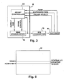
- FIG 3 is a schematic illustration of the imager 38 that shows the sensor array 62 and its controller 64 that sets various operating parameters on the array.
- Most sensor arrays include exposure control and gain control settings that are determined by the decoder as discussed above. For AEC, an average level of pixel brightness is determined and if the brightness is below a threshold level, the exposure time is increased. Likewise, for AGC, the gain on amplification components in the array output stage is increased if the signal received from the array is not sufficiently bright to decode.
- the array controller 64 outputs and the decoder analyzes an entire frame of MxN pixel data to make the brightness determination. The transfer time and processing time for such a large number of pixels is burdensome, especially when several iterations are necessary to achieve proper exposure.
- the frame selection feature of the array is utilized. As shown in Figure 5 , the array controller skips a first number K rows and then outputs a middle M/10, or ten percent, of rows for brightness analysis so that only rows K through K+M/10 are output, transferred, and analyzed. Once the proper exposure is achieved, a full image can be output for decoding if necessary. Based on the present state of imager technology, the portion of pixel data can be acquired every 5 milliseconds as opposed to every 30 milliseconds for full frames of pixel data, resulting in approximately a six-fold reduction in AEC processing time.
- Figure 4 outlines an image processing routine 100 that includes the analysis of a portion of pixel data for both an initial decode attempt and auto-exposure analysis.
- the routine starts and at 115 the array controller selects the centrally cropped region defined by the center ten percent of rows of the sensor array by instructing the array to skip the first 45% of the rows prior to reading out pixel data and then outputting only the next 10% of the rows.
- the pixel data from the selected rows is acquired.
- the data from the selected rows is sent to the decoder which attempts to decode the data.
- the target indicia is a 1-D barcode and the user has oriented the frame so that it is parallel to the horizontal axis of the barcode and the barcode is centered in the frame, it is possible that this decode will be successful, and if so the processing routine ends.
- the decoder may determine pixel brightness using the same techniques currently employed for analyzing full frames of pixel data. Of course, alternative pixel analysis techniques that can be used to determine proper exposure time could also be practiced on the subset of pixel data acquired at 120. If at 132, the pixel brightness is within the acceptable range, at 160 a full image is acquired and passed to the decoder for full scale decoding.
- the present exposure time setting is compared to the maximum allowable exposure time. If the exposure time can be increased, at 140 the exposure time is increased by a preset increment, such as 6.26% of the maximum time and another cropped frame of pixel data is acquired at 120. If the exposure time is already at its maximum value, at 145 the present gain setting is compared to its maximum allowable value. If the gain can be increased, it is increased by a preset increment at 150 and another cropped frame of pixel data is acquired at 120. It will be appreciated by one of skill in the art that the precise order in which adjustments are made to the exposure time and gain can be varied, for example by increasing gain first and then exposure time if the gain setting increase is not sufficient.
- the imager thus intakes and analyzes a relatively small subset of pixel data to attempt to decode the indicia in the target region. If the indicia is not decoded, the same subset of pixel data is used to adjust the exposure time and gain of the array to increase the likelihood of a successful decode in subsequent scans. Once the image is of sufficient quality, data from an enlarged or the entire array or a subsequent cropped frame of the array can be decoded with greater confidence.
Landscapes
- Physics & Mathematics (AREA)
- Engineering & Computer Science (AREA)
- Electromagnetism (AREA)
- Artificial Intelligence (AREA)
- Toxicology (AREA)
- General Health & Medical Sciences (AREA)
- Health & Medical Sciences (AREA)
- Computer Vision & Pattern Recognition (AREA)
- General Physics & Mathematics (AREA)
- Theoretical Computer Science (AREA)
- Image Input (AREA)
- Facsimile Scanning Arrangements (AREA)
- Exposure And Positioning Against Photoresist Photosensitive Materials (AREA)
Claims (7)
- Bildgerät (38), das Kennzeichen verarbeitet, umfassend:eine zweidimensionale Anordnung von Sensoren (62), die geeignet sind, Daten zu erfassen, die einer Lichtmenge entsprechen, die durch die Sensoren während einer Belichtungszeit gesammelt werden, um ein Bild einer Zieloberfläche (11), auf die das Bildgerät gerichtet ist, zu erzeugen, und wobei die zweidimensionale Anordnung von Sensoren (62) geeignet ist, Anordnungssegmentdaten auszugeben, die einem Segment der zweidimensionalen Anordnung von Sensoren entsprechen, wobei das Segment einem Satz benachbarter Reihen von Sensoren entspricht, die über einer Mitte der Anordnung von Sensoren (62) angeordnet sind, wobei der Satz benachbarter Reihen von Sensoren nicht mehr als 10 % einer Gesamtzahl von Reihen von Sensoren der Anordnung umfasst und wobei vergrößerte Anordnungsdaten den Daten von einer vorbestimmten vergrößerten Zahl von den Sensoren in der Anordnung entsprechen;einen Decoder (40), der die Anordnungssegmentdaten während einer Dateneingabeperiode eingibt, die kürzer ist als eine Zeitperiode, die erforderlich ist, um die vergrößerten Anordnungsdaten einzugeben, wobei der Decoder (40) eine modifizierte Belichtungszeit basierend auf einer Belichtungsqualität von den Anordnungssegmentdaten bestimmt, wobei ein Maß für die Belichtungsqualität ein Maß eines durchschnittlichen Lichtniveaus umfasst;ein Belichtungsqualitätssteuergerät (64), das ein nachfolgendes Erfassen von Lichtdaten steuert/regelt, welches während einer modifizierten Belichtungszeitdauer auftreten soll;und wobei der Decoder (40) selektiv Steuersignale an die Anordnung sendet, um sie zu veranlassen, die vergrößerten Anordnungsdaten für eine nachfolgende Kennzeichenverarbeitung auszugeben.
- Bildgerät (38) nach Anspruch 1, wobei der Decoder (40) Anordnungssegmentdaten interpretiert, um Informationen, die in einem Barcode-Bild, das durch die Sensoren in dem Segment erfasst wurde, auszugeben.
- Bildgerät (38) nach Anspruch 1 oder 2, wobei die vergrößerten Anordnungsdaten den Daten von im Wesentlichen allen Sensoren in der Anordnung entsprechen.
- Verfahren (100), das ein Kennzeichen verarbeitet, das auf einer Zieloberfläche (11) vorliegt, mit einem Bildgerät (38), das eine zweidimensionale Anordnung von Lichtsensoren (62) enthält, die Lichtdaten erfassen, die Licht entsprechen, das während einer Belichtungszeit von einer Zieloberfläche (11) auf das Bildgerät (38) zurückreflektiert wurde, um Lichtsensordaten zu erzeugen, die einem Bild der Zieloberfläche (11) entsprechen, wobei das Verfahren umfasst:Auswählen (110) einer ersten Teilmenge von Lichtsensoren aus der zweidimensionalen Anordnung, die zu verwenden sind, um eine geeignete Dauer der Belichtungszeit zu bestimmen, wobei die erste Teilmenge von Lichtsensoren einem Satz benachbarter Reihen von Lichtsensoren entspricht, die über einer Mitte der Anordnung von Lichtsensoren (62) angeordnet sind, wobei der Satz benachbarter Reihen von Lichtsensoren nicht mehr als 10 % der Gesamtanzahl von Reihen von Lichtsensoren in der Anordnung entspricht;Erfassen (120) von Lichtsensoranordnungsdaten mit der Anordnung von Sensoren während der Belichtungszeit;Eingeben (125, 130) von Lichtdaten von der ausgewählten ersten Teilmenge von Lichtsensoren in ein Belichtungsqualitätssteuergerät (64);Einstellen (135) der Dauer der Belichtungszeit und/oder einer Ausgabekomponenten-Verstärkungseinstellung basierend auf Lichtdaten von Sensoren in der ausgewählten ersten Teilmenge von Lichtsensoren; undAuswählen einer zweiten, größeren Teilmenge von Lichtsensoren und Eingeben von Lichtdaten von der zweiten Teilmenge von Lichtsensoren bei einer nachfolgenden Kennzeichenverarbeitung.
- Verfahren nach Anspruch 4, wobei Daten von der Teilmenge von Lichtsensoren in das Belichtungsqualitätssteuergerät eingegeben werden, indem eine erste Anzahl von Reihen von Sensoren übersprungen wird, bevor Sensordaten zu dem Belichtungsqualitätssteuergerät (64) übertragen werden.
- Verfahren nach Anspruch 4 oder 5, wobei die Dauer der Belichtungszeit und/oder die Ausgabekomponenten-Verstärkungseinstellung eingestellt wird durch:Berechnen eines durchschnittlichen Sensorsignalniveaus und Vergleichen des durchschnittlichen Signalniveaus mit einem vorbestimmten Minimalsignal; undVerlängern der Dauer der Belichtungszeit und/oder der Ausgabekomponenten-Verstärkungseinstellung bei einer nachfolgenden Erfassung von Lichtsensordaten, wenn das durchschnittliche Signalniveau geringer ist als das Minimalsignal.
- Verfahren nach einem der Ansprüche 4 bis 6, welches das Decodieren der Daten von der ersten Teilmenge von Lichtsensoren umfasst, um Informationen zu bestimmen, die in dem Kennzeichen codiert sind.
Applications Claiming Priority (2)
| Application Number | Priority Date | Filing Date | Title |
|---|---|---|---|
| US11/442,912 US7227117B1 (en) | 2006-05-30 | 2006-05-30 | High speed auto-exposure control |
| PCT/US2007/011610 WO2007142787A2 (en) | 2006-05-30 | 2007-05-15 | High speed auto-exposure control |
Publications (3)
| Publication Number | Publication Date |
|---|---|
| EP2084647A2 EP2084647A2 (de) | 2009-08-05 |
| EP2084647A4 EP2084647A4 (de) | 2012-05-23 |
| EP2084647B1 true EP2084647B1 (de) | 2014-04-23 |
Family
ID=38090146
Family Applications (1)
| Application Number | Title | Priority Date | Filing Date |
|---|---|---|---|
| EP07794877.6A Active EP2084647B1 (de) | 2006-05-30 | 2007-05-15 | Hochgeschwindigkeits-automatik-belichtungssteuerung |
Country Status (3)
| Country | Link |
|---|---|
| US (1) | US7227117B1 (de) |
| EP (1) | EP2084647B1 (de) |
| WO (1) | WO2007142787A2 (de) |
Families Citing this family (16)
| Publication number | Priority date | Publication date | Assignee | Title |
|---|---|---|---|---|
| US8794520B2 (en) * | 2008-09-30 | 2014-08-05 | Hand Held Products, Inc. | Method and apparatus for operating indicia reading terminal including parameter determination |
| US8628015B2 (en) | 2008-10-31 | 2014-01-14 | Hand Held Products, Inc. | Indicia reading terminal including frame quality evaluation processing |
| FI20086240A7 (fi) | 2008-12-23 | 2010-06-24 | Palodex Group Oy | Kuvalevyn lukijalaitteen puhdistusjärjestelmä |
| FI20086241L (fi) | 2008-12-23 | 2010-06-24 | Palodex Group Oy | Kuvalevyn lukijalaite |
| US8256678B2 (en) * | 2009-08-12 | 2012-09-04 | Hand Held Products, Inc. | Indicia reading terminal having image sensor and variable lens assembly |
| US9514344B2 (en) * | 2010-11-10 | 2016-12-06 | Datalogic ADC, Inc. | Adaptive data reader and method of operating |
| US8408464B2 (en) | 2011-02-03 | 2013-04-02 | Metrologic Instruments, Inc. | Auto-exposure method using continuous video frames under controlled illumination |
| CN102298953B (zh) * | 2011-06-03 | 2014-04-30 | 武汉纺织大学 | 带保护字的二维游程长度受限约束的编解码器及使用方法 |
| US8646692B2 (en) | 2011-09-30 | 2014-02-11 | Hand Held Products, Inc. | Devices and methods employing dual target auto exposure |
| WO2013107016A1 (en) * | 2012-01-19 | 2013-07-25 | Honeywell International Inc | Apparatus comprising imaging system |
| US10368053B2 (en) * | 2012-11-14 | 2019-07-30 | Qualcomm Incorporated | Structured light active depth sensing systems combining multiple images to compensate for differences in reflectivity and/or absorption |
| US9361502B2 (en) * | 2014-07-31 | 2016-06-07 | Symbol Technologies, Llc | System for, and method of, controlling target illumination for an imaging reader |
| US9594936B1 (en) | 2015-11-04 | 2017-03-14 | Datalogic Usa, Inc. | System and method for improved reading of data from reflective surfaces of electronic devices |
| US10244180B2 (en) * | 2016-03-29 | 2019-03-26 | Symbol Technologies, Llc | Imaging module and reader for, and method of, expeditiously setting imaging parameters of imagers for imaging targets to be read over a range of working distances |
| US9646188B1 (en) * | 2016-06-02 | 2017-05-09 | Symbol Technologies, Llc | Imaging module and reader for, and method of, expeditiously setting imaging parameters of an imager based on the imaging parameters previously set for a default imager |
| DE102024209629A1 (de) * | 2024-10-01 | 2026-04-02 | Pepperl+Fuchs Se | Verfahren und Vorrichtung zur optischen Erfassung mindestens eines Codes |
Family Cites Families (7)
| Publication number | Priority date | Publication date | Assignee | Title |
|---|---|---|---|---|
| US6347163B2 (en) * | 1994-10-26 | 2002-02-12 | Symbol Technologies, Inc. | System for reading two-dimensional images using ambient and/or projected light |
| US5354977A (en) * | 1992-02-27 | 1994-10-11 | Alex Roustaei | Optical scanning head |
| US7268924B2 (en) * | 2001-01-22 | 2007-09-11 | Hand Held Products, Inc. | Optical reader having reduced parameter determination delay |
| US7038820B1 (en) * | 2002-04-03 | 2006-05-02 | Eastman Kodak Company | Automatic exposure control for an image sensor |
| US7605852B2 (en) * | 2004-05-17 | 2009-10-20 | Micron Technology, Inc. | Real-time exposure control for automatic light control |
| US20050253937A1 (en) * | 2004-05-17 | 2005-11-17 | Micron Technology, Inc. | Real-time exposure control for automatic light control |
| US20060011724A1 (en) * | 2004-07-15 | 2006-01-19 | Eugene Joseph | Optical code reading system and method using a variable resolution imaging sensor |
-
2006
- 2006-05-30 US US11/442,912 patent/US7227117B1/en not_active Expired - Lifetime
-
2007
- 2007-05-15 WO PCT/US2007/011610 patent/WO2007142787A2/en not_active Ceased
- 2007-05-15 EP EP07794877.6A patent/EP2084647B1/de active Active
Also Published As
| Publication number | Publication date |
|---|---|
| EP2084647A2 (de) | 2009-08-05 |
| WO2007142787A2 (en) | 2007-12-13 |
| WO2007142787A3 (en) | 2009-04-16 |
| EP2084647A4 (de) | 2012-05-23 |
| US7227117B1 (en) | 2007-06-05 |
Similar Documents
| Publication | Publication Date | Title |
|---|---|---|
| EP2084647A2 (de) | Hochgeschwindigkeits-automatik-belichtungssteuerung | |
| US7637430B2 (en) | Picture taking optical reader | |
| US7428079B2 (en) | Bar code reading device having partial frame image capture operating mode | |
| US7874485B2 (en) | Adaptive optical image reader | |
| JP5414685B2 (ja) | 複数の画像フレームを使用してパターンを読取るシステム、及び方法 | |
| US7559473B2 (en) | Sensor for activating an aiming pattern of a handheld scanner | |
| US6598797B2 (en) | Focus and illumination analysis algorithm for imaging device | |
| US20040118926A1 (en) | System and method for auto focusing an optical code reader | |
| EP1112547B1 (de) | Optische symbolanzeige | |
| US20060022052A1 (en) | System and method for decoding optical codes read by an imager-based optical code reader | |
| US10110829B2 (en) | System and method for determination and adjustment of camera parameters using multi-gain images | |
| EP2249284A2 (de) | Optisches Lesegerät mit Partial-Frame-Betriebsmodus | |
| WO2006019847A1 (en) | Optical code reading system and method using a variable resolution imaging sensor | |
| US20070272756A1 (en) | Hand held bar code reader with improved image capture | |
| EP2021974B1 (de) | Kamera-gehäuseauswahl basierend auf strichcodeeigenschaften | |
| JP4559485B2 (ja) | 撮像装置ベースの光符号読取機の動作検出感度を低減するシステム及び方法 | |
| US8320702B2 (en) | System and method for reducing specular reflection | |
| US7428991B2 (en) | 1-D barcode decoding with 2-D sensor array | |
| US12082325B1 (en) | Methods and apparatus for providing illumination during operation of an indicia reader | |
| EP2310896B1 (de) | Einen zweidimensionalen bildsensor verwendender eindimensionaler strichcodeleser | |
| US12363431B2 (en) | Use of distant measurement to aid in vision applications in handheld scanner devices | |
| US12596899B1 (en) | Systems and methods for mitigating specular reflection |
Legal Events
| Date | Code | Title | Description |
|---|---|---|---|
| PUAI | Public reference made under article 153(3) epc to a published international application that has entered the european phase |
Free format text: ORIGINAL CODE: 0009012 |
|
| 17P | Request for examination filed |
Effective date: 20081126 |
|
| AK | Designated contracting states |
Kind code of ref document: A2 Designated state(s): AT BE BG CH CY CZ DE DK EE ES FI FR GB GR HU IE IS IT LI LT LU LV MC MT NL PL PT RO SE SI SK TR |
|
| AX | Request for extension of the european patent |
Extension state: AL BA HR MK RS |
|
| DAX | Request for extension of the european patent (deleted) | ||
| RBV | Designated contracting states (corrected) |
Designated state(s): DE FR GB |
|
| A4 | Supplementary search report drawn up and despatched |
Effective date: 20120423 |
|
| RIC1 | Information provided on ipc code assigned before grant |
Ipc: G06K 7/10 20060101AFI20120417BHEP |
|
| GRAP | Despatch of communication of intention to grant a patent |
Free format text: ORIGINAL CODE: EPIDOSNIGR1 |
|
| INTG | Intention to grant announced |
Effective date: 20131204 |
|
| GRAS | Grant fee paid |
Free format text: ORIGINAL CODE: EPIDOSNIGR3 |
|
| GRAA | (expected) grant |
Free format text: ORIGINAL CODE: 0009210 |
|
| AK | Designated contracting states |
Kind code of ref document: B1 Designated state(s): DE FR GB |
|
| REG | Reference to a national code |
Ref country code: GB Ref legal event code: FG4D |
|
| REG | Reference to a national code |
Ref country code: DE Ref legal event code: R096 Ref document number: 602007036264 Country of ref document: DE Effective date: 20140605 |
|
| REG | Reference to a national code |
Ref country code: DE Ref legal event code: R097 Ref document number: 602007036264 Country of ref document: DE |
|
| PLBE | No opposition filed within time limit |
Free format text: ORIGINAL CODE: 0009261 |
|
| REG | Reference to a national code |
Ref country code: FR Ref legal event code: ST Effective date: 20150130 |
|
| STAA | Information on the status of an ep patent application or granted ep patent |
Free format text: STATUS: NO OPPOSITION FILED WITHIN TIME LIMIT |
|
| 26N | No opposition filed |
Effective date: 20150126 |
|
| REG | Reference to a national code |
Ref country code: DE Ref legal event code: R097 Ref document number: 602007036264 Country of ref document: DE Effective date: 20150126 |
|
| PG25 | Lapsed in a contracting state [announced via postgrant information from national office to epo] |
Ref country code: FR Free format text: LAPSE BECAUSE OF NON-PAYMENT OF DUE FEES Effective date: 20140623 |
|
| REG | Reference to a national code |
Ref country code: DE Ref legal event code: R082 Ref document number: 602007036264 Country of ref document: DE Representative=s name: LKGLOBAL | LORENZ & KOPF PARTG MBB PATENTANWAE, DE Ref country code: DE Ref legal event code: R082 Ref document number: 602007036264 Country of ref document: DE Representative=s name: SCHUMACHER & WILLSAU PATENTANWALTSGESELLSCHAFT, DE Ref country code: DE Ref legal event code: R081 Ref document number: 602007036264 Country of ref document: DE Owner name: SYMBOL TECHNOLOGIES, LLC (N.D. GES. D. STAATES, US Free format text: FORMER OWNER: SYMBOL TECHNOLOGIES, INC., HOLTSVILLE, N.Y., US Ref country code: DE Ref legal event code: R082 Ref document number: 602007036264 Country of ref document: DE Representative=s name: KOPF, KORBINIAN, DIPL.-ING.UNIV., MA, DE |
|
| REG | Reference to a national code |
Ref country code: DE Ref legal event code: R082 Ref document number: 602007036264 Country of ref document: DE Representative=s name: LKGLOBAL | LORENZ & KOPF PARTG MBB PATENTANWAE, DE Ref country code: DE Ref legal event code: R082 Ref document number: 602007036264 Country of ref document: DE Representative=s name: KOPF, KORBINIAN, DIPL.-ING.UNIV., MA, DE Ref country code: DE Ref legal event code: R082 Ref document number: 602007036264 Country of ref document: DE Representative=s name: LKGLOBAL LORENZ UND KOPF PATENTANWALT, ATTORNE, DE |
|
| REG | Reference to a national code |
Ref country code: DE Ref legal event code: R082 Ref document number: 602007036264 Country of ref document: DE Representative=s name: LKGLOBAL | LORENZ & KOPF PARTG MBB PATENTANWAE, DE Ref country code: DE Ref legal event code: R082 Ref document number: 602007036264 Country of ref document: DE Representative=s name: LKGLOBAL LORENZ UND KOPF PATENTANWALT, ATTORNE, DE |
|
| P01 | Opt-out of the competence of the unified patent court (upc) registered |
Effective date: 20230416 |
|
| PGFP | Annual fee paid to national office [announced via postgrant information from national office to epo] |
Ref country code: GB Payment date: 20260421 Year of fee payment: 20 |
|
| PGFP | Annual fee paid to national office [announced via postgrant information from national office to epo] |
Ref country code: DE Payment date: 20260421 Year of fee payment: 20 |