EP2084997A1 - Présentation de marchandises - Google Patents
Présentation de marchandises Download PDFInfo
- Publication number
- EP2084997A1 EP2084997A1 EP08002046A EP08002046A EP2084997A1 EP 2084997 A1 EP2084997 A1 EP 2084997A1 EP 08002046 A EP08002046 A EP 08002046A EP 08002046 A EP08002046 A EP 08002046A EP 2084997 A1 EP2084997 A1 EP 2084997A1
- Authority
- EP
- European Patent Office
- Prior art keywords
- goods display
- side wall
- connector
- floor
- wall elements
- Prior art date
- Legal status (The legal status is an assumption and is not a legal conclusion. Google has not performed a legal analysis and makes no representation as to the accuracy of the status listed.)
- Withdrawn
Links
- 239000000463 material Substances 0.000 claims abstract description 41
- 238000003860 storage Methods 0.000 claims abstract description 11
- 230000003014 reinforcing effect Effects 0.000 claims description 35
- 230000004308 accommodation Effects 0.000 abstract 1
- 239000000853 adhesive Substances 0.000 description 17
- 230000001070 adhesive effect Effects 0.000 description 17
- 238000010276 construction Methods 0.000 description 8
- 230000007704 transition Effects 0.000 description 5
- 210000002105 tongue Anatomy 0.000 description 4
- 238000009434 installation Methods 0.000 description 3
- NJPPVKZQTLUDBO-UHFFFAOYSA-N novaluron Chemical compound C1=C(Cl)C(OC(F)(F)C(OC(F)(F)F)F)=CC=C1NC(=O)NC(=O)C1=C(F)C=CC=C1F NJPPVKZQTLUDBO-UHFFFAOYSA-N 0.000 description 3
- 230000015572 biosynthetic process Effects 0.000 description 2
- 239000002131 composite material Substances 0.000 description 2
- 238000000151 deposition Methods 0.000 description 2
- 238000004519 manufacturing process Methods 0.000 description 2
- 230000013011 mating Effects 0.000 description 2
- 230000002787 reinforcement Effects 0.000 description 2
- 230000000007 visual effect Effects 0.000 description 2
- 240000006829 Ficus sundaica Species 0.000 description 1
- 238000004026 adhesive bonding Methods 0.000 description 1
- 230000002349 favourable effect Effects 0.000 description 1
- 238000003780 insertion Methods 0.000 description 1
- 230000037431 insertion Effects 0.000 description 1
- 238000000034 method Methods 0.000 description 1
- 239000000123 paper Substances 0.000 description 1
- 230000002093 peripheral effect Effects 0.000 description 1
- 230000002269 spontaneous effect Effects 0.000 description 1
Images








Classifications
-
- A—HUMAN NECESSITIES
- A47—FURNITURE; DOMESTIC ARTICLES OR APPLIANCES; COFFEE MILLS; SPICE MILLS; SUCTION CLEANERS IN GENERAL
- A47F—SPECIAL FURNITURE, FITTINGS, OR ACCESSORIES FOR SHOPS, STOREHOUSES, BARS, RESTAURANTS OR THE LIKE; PAYING COUNTERS
- A47F5/00—Show stands, hangers, or shelves characterised by their constructional features
- A47F5/10—Adjustable or foldable or dismountable display stands
- A47F5/11—Adjustable or foldable or dismountable display stands made of cardboard, paper or the like
- A47F5/112—Adjustable or foldable or dismountable display stands made of cardboard, paper or the like hand-folded from sheet material
- A47F5/116—Shelving racks
-
- A—HUMAN NECESSITIES
- A47—FURNITURE; DOMESTIC ARTICLES OR APPLIANCES; COFFEE MILLS; SPICE MILLS; SUCTION CLEANERS IN GENERAL
- A47B—TABLES; DESKS; OFFICE FURNITURE; CABINETS; DRAWERS; GENERAL DETAILS OF FURNITURE
- A47B87/00—Sectional furniture, i.e. combinations of complete furniture units, e.g. assemblies of furniture units of the same kind such as linkable cabinets, tables, racks or shelf units
- A47B87/02—Sectional furniture, i.e. combinations of complete furniture units, e.g. assemblies of furniture units of the same kind such as linkable cabinets, tables, racks or shelf units stackable ; stackable and linkable
- A47B87/0207—Stackable racks, trays or shelf units
- A47B87/0246—Shelves stackable by means of separate vertical distance-holders therebetween
Definitions
- the invention relates to a goods display of folding material such as cardboard, corrugated cardboard or the like, with at least two side walls and at least one separate connected to the at least two side walls by means of a plug connection bottom element.
- Such merchandise displays are preferably used in retail to present products and to encourage spontaneous purchases.
- the goods displays are set up in the sales room, so that the products placed therein occupy a prominent position in relation to the products on the shelves.
- a display shelf which comprises two side walls and a rear wall and can accommodate shelves and chutes.
- recesses are provided, can be plugged into the insertion and support tabs, which are arranged vertically pointing up and down to the shelves or chutes.
- the chutes can be tilted to allow a better presentation of the products.
- the disadvantage here is that the display shelf can not be adjusted in its overall height by the user himself to the required height, and the individual shelves are designed variable in height.
- Another sales stand is from the DE 29610442 U1 known. This has two side walls, and a rear wall, wherein in both side walls each at the same height horizontal slots are introduced. In this, the previously folded shelves are inserted, which are received by shaped side edges flush in the slots.
- the US 5984120 shows a goods shelf whose floors are formed of individual folded boxes.
- the individual boxes are stacked on each other and connected by protruding tabs and matching receiving pockets.
- the individual floors are formed by stacked, forward sloping boxes.
- the boxes are anchored with tabs in the box below.
- the tabs are located on the one-piece box, which ensures sufficient stability despite the inclination.
- a goods display of folding material such as cardboard, corrugated cardboard or the like is provided with at least two side walls and at least one separate connected to the at least two side walls by means of a plug bottom element, said at least two side walls each have at least two superimposed side wall elements, and the side wall elements by means an interposed connector are connected together and the connector forms a part of the bottom element. Since the connectors are already part of the floor elements, the side elements need not have protruding connectors. This gives the sidewall elements the possibility of a more flexible design. Also can be realized by the juxtaposition of sidewall elements different construction options, so that the most diverse customer requirements can be met.
- the bottom element in the region of at least two side edges can each have at least one connection tab as a connector, which extend from a support surface of the bottom element substantially at right angles up and down.
- the formation of the connector as connecting straps offers the possibility to produce at least parts of the bottom element as a folding blank and to form the connecting straps by folding. Due to the substantially rectangular arrangement of the connecting straps, the structure can be carried out in particular by simply placing side wall elements on the floor element.
- the stacking surfaces of the adjoining side wall elements touch.
- touching the side wall elements is formed on the outer wall of the goods display a continuous side wall, which creates a visually pleasing impression.
- the receiving pocket of the side wall element may be designed to be closed on the outer surface of the side wall element facing away from the bottom element. This leads, in particular together with the touching side wall elements to the impression of a one-piece side wall.
- the side wall element is formed from at least three interconnected material layers, the individual material layers are separate material layers and / or folded material layers and the receiving pocket for receiving the connector in each case by a recess in at least one of the inner material layers is formed.
- the construction of the side wall element of several layers of material ensures increased stability. In addition, this allows the inclusion of the connecting tab in the interior of the side wall element, so that it does not appear to the outside in appearance.
- a further embodiment of the invention may consist in that the receiving pocket for receiving the connector is formed by a recess in more than one of the material layers and the innermost, the inner surface of the side wall element forming material layer facing the bottom element has a less deep recess in the vertical direction than an adjacent material layer. This serves for the horizontal fixation and allows the inclusion of a transition region between the connector and the support body, so that it is no longer visible.
- the bottom element has a support body and the connector is arranged by means of a connecting web at a distance from the support body and the connecting web is received by the less deep recess.
- the connector can thus be inserted far enough into the receptacle, whereby this is secured transversely to the side wall element. Also, so that the connecting web is prevented from slipping.
- the height of a window formed by superimposed less deep recesses substantially the thickness of the connecting web equivalent. If side wall elements are stacked on top of each other, windows form through the adjacent, less deep recesses. Now, if a bottom element is inserted for attachment between the two side wall elements, the connection tabs engage in both side wall elements and the connecting web between the connection tab and the support body is positively received in the window.
- a further embodiment may provide that at least one material layer of the bottom element together with the at least one connector is formed from a common folding blank or at least two independent folding blanks.
- a common folding blank By using a common folding blank additional splices or connections between individual components are avoided. But even if the connectors are formed on at least two independent Faltzu motherboarden still results in a production advantage over a separate production of connectors.
- the at least two independent folding blanks are i.d.R. connected together and thus correspond to a one-piece joint folding blank.
- the at least two independent folding blanks can also be connected to other components of the floor element and come to rest against each other in such a way that their impression corresponds to that of a common folding blank.
- the at least one connector is formed by folding and positive connection of at least two independent portions of a common folding blank or portions of at least two independent folding blanks.
- the two sub-areas that form the connector can be assembled by this user by himself.
- the material areas which later form the connector are laid flat during transport and are erected shortly before the use of the floor element, whereby damage to the connector during transport can be excluded. In this way, a high accuracy of fit is guaranteed.
- a further embodiment of the inventive display is that the common folding blank or the at least two independent material blanks for the at least one connector and the support body are folded into an enveloping body, which at least partially encase a reinforcing core formed by at least one material layer. As a result, the stability of the support body can be increased.
- Another user-friendly design of the floor element may provide that the enveloping body can be transferred from a flat transport position to an erect use position and the enveloping body surrounds a cavity in the position of use, in which the reinforcing core is laterally inserted and the cavity laterally at least partially from that by folding and positive connection formed connector is closed.
- the flattened transport position of the enveloping body allows a space-saving transport of the individual parts of the goods display.
- the enveloping body in its transport position and the reinforcing core are essentially flat and thus avoid, for example, the damage of the connector during transport.
- An increased variability of the display of goods can be achieved in that a floor is formed from side wall elements of the same height and one floor element, that several floors are stacked and at least two floors have a different height. This gives the user the opportunity to choose from a variety of floors of different heights and customize the display of goods to his respective needs. In particular, this makes it possible for each different sized products to form a matching floor. Also, the total height of the goods display can be varied as desired.
- a rear wall element is provided which is connected to the side wall elements and forms a floor element together with this. This reduces the number of parts and makes the design easier for the user.
- An advantageous development of the embodiment provides that from a floor element of certain height and a floor element a floor is formed, several floors are stacked on each other and at least two floors have a different height. This ensures that are formed by prefabricated floor elements to the respective needs adapted floors. The reduced number of parts allows a faster and simpler structure.
- a further embodiment provides that the side edge of the support body is longer than the depth dimension of a connector arranged thereon.
- the bottom element can thereby extend over the entire depth of the goods display without the tabs appear outward. This design thus offers a stable and shapely structure.
- the support body is rectangular and the connectors are only arranged respectively on the shorter side edges of the support body.
- a rectangular goods display is formed whose longitudinal side is freely accessible and facilitates the assembly of the display.
- a further embodiment consists in that the connectors have in their entire vertical extent at least twice the thickness of the support body, preferably three times the thickness of the support body. Such a design increases the security or stability of the goods display. The connectors thus have enough space to support themselves in the side wall elements.
- the goods display can also be developed by the bottom element transverse side edges, on each of which a connector is arranged, and having longitudinal side edges, wherein on the longitudinal side edges, each a safety bar is provided, and the one of the safety strips of the shelf of the floor element substantially upwards and the other safety strip extends substantially downwards.
- a development of the invention provides that the side wall elements or a wall assembly are positioned on a pedestal and the base has at least two vertically extending upward plug-in elements which engage in receiving pockets of the side wall elements.
- the goods display can be brought into the handle height or viewing height of the customer.
- the stability can be increased by the base.
- the invention comprises a flattened kit for a goods display with at least one bottom element, which has as part of a connector, and at least two flat stacked and stackable with each other by means of the connector side wall elements.
- the kit is relatively compact (in a flat position) deliver and upright on site or for equipping with goods very easy.
- Fig.1 shows a goods display 1, which has a plurality of floor elements 5 and floor elements 4.
- the lowest floor element 5 stands on a pedestal 6, which in turn stands on a pallet 7.
- two side wall elements 2 and one rear wall element 3 form a floor element 5.
- the rear wall elements 3 and the side wall elements 2 are each connected to one another via a vertically extending hinge 26 , Between the lowermost floor element 5 and the base 6 also runs a circumferential abutting edge 30. Between the floor elements 5 bottom elements 4 are inserted.
- safety strips 32 are integrally formed on the floor element 4 in the installation position in front and behind.
- the rear safety bar 32 protects thin goods from slipping between the floor element 4 and the rear wall element 3.
- Each of the floor elements 5 has respective receiving pockets 14 for receiving as connecting straps 10 (s. FIG. 2 ) configured connectors, which are located on the bottom element 4.
- the openings 31 in the illustrated embodiment have a rectangular shape with rounded corners, but can be designed in any form or even omitted.
- Each of the floor elements 5 in each case has a height E, which may differ from the height E of a further floor element 5. In particular, by selecting floor elements of different heights, the user obtains the possibility of adapting the individual floors, formed by floor element 5 and floor element 4, to the respective products to be accommodated in the floor.
- the side wall elements 2 and floor elements 4 have a depth T, which allows customers to see all arranged on a floor element goods and to remove them conveniently.
- the depth T is defined by the horizontally measured length of the side wall element 2 from the rear wall element 3 to a front edge 13 of the floor element 5. Upwards, the goods display 1 is completed with a floor element 5, but also a bottom element 4
- a bottom element 4 each with a connecting strap 10 designed as a connector on the short sides 22, a support surface 11 and in each case a safety strip 32 the long side 23 is in Fig. 2 to see.
- the storage surface 11 is formed by a rectangular surface, which is limited in the illustrated embodiment by the safety strips 32. It serves in the intended use for storing goods on the bottom element 4.
- the connecting straps 10 extend from the storage surface 11 with a measure H, measured in each case from the storage surface 11 at the top or from the underside of the bottom element 4 forming surface at an angle of substantially 90 ° upwards and downwards.
- the length of the connecting straps 10 in the direction of the depth T is less than the depth T, whereby the connecting straps 10 are not visible on the front edge 13 of the floor element 5.
- the connecting straps 10 are arranged centrally in the direction of the depth T.
- the safety strips 32 are formed directly on a support body 25 of the bottom element 4 and extend with a dimension S, measured from the support surface 11 at an angle of substantially 90 ° upwards. In order to be able to reliably fulfill their function, the safety strips 32 extend in the longitudinal direction over the entire length of the support surface 11.
- the connecting straps 10 are connected to the support body 25 via connecting webs 16 and spaced therefrom.
- the support body is formed by a reinforcing core 8 and the overlying shelf surface 11.
- Fig. 3 an enlarged view of the corner region of the bottom element 4 can be seen. Visible is the reinforcing core 8 and an enveloping body 9, which is fastened on the reinforcing core 8 and, by folding, forms the connecting flaps 10 and safety strips 32.
- the reinforcing core 8 in the illustrated embodiment comprises three reinforcing elements 17 made of corrugated cardboard or the like.
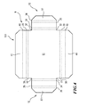
- For the formation of the enveloping body 9 is on the reinforcing elements 17 of in Fig. 4 shown blank 9.1 laid, which forms a shelf 11 between the safety strips 32 and is folded around the reinforcing core 8.
- the storage surface 11 forms the region of the bottom element 4, which serves in the later intended use for storing goods.
- the region of the support surface 11 of the blank 9.1, together with the reinforcing core 8, forms a support body 25.
- the blank 9.1 with the area for the depositing surface 11 is placed on the reinforcing core 8 and connected thereto.
- the part of the blank 9.1 projecting beyond the reinforcing core 8 is folded upwards at the folding lines 33 at an angle of 90 °, where it folds outwards by 180 ° at the fold lines 34, so that an upper connector strip 47 arises, and folded down again at the fold lines 35 by 180 °, so that a lower header 48 is formed, to then be folded again at the fold lines 36 by 90 °.
- the remaining folding tabs 37 are adhered to the underside of the reinforcing core 8.
- the upwardly and downwardly facing plug-in strips 47, 48 correspond in their height H in each case essentially to the thickness D of the connecting web 16.
- the thickness D of the connecting web 16 corresponds to the total thickness of a layer 11 forming the material layer of the blank 9.1, the Reinforcement core 8 and a folded-down folding tab 37, 41.
- the upward and downward facing headers 47, 48 form in their entirety the connecting plate 10.
- the folding blank for the enveloping body 9.1 so the areas are already formed, which later form the connecting tabs 10 after folding.
- the folding blank for the enveloping body 9.1 can be embodied in one piece as well as in several parts, with the regions for the connecting flaps 10 also being already formed in the multi-part variant.
- the folding blank for the enveloping body 9.1 or the at least two independent folding blanks surround or encase the reinforcing core 8 formed from at least one material layer.
- the folding tabs 37, 41 on the blank 9.1 have bevelled corners, so that they do not overlap each other during the bonding on the underside of the support body 25.
- the safety strip 32 on the longer side 23 of the bottom element 4 serves as protection against accidental falling out of objects during later use of the bottom element 4.
- the connecting web 16 can also be connected as a separate element with a separate supporting body 25 and / or separate connecting straps 10.
- Fig. 5 shows a reinforcing element 17 for the reinforcing core 8.
- elements 16 ' are formed for connecting webs 16, around which later the connecting flaps 10, formed from the blank 9.1, are folded.
- three reinforcing elements 17 are connected to each other in the present embodiment.
- the bottom element 4 can also vary the number of reinforcing elements 17, or the reinforcing core 8 can be completely dispensed with.
- the reinforcing element 17 consists of at least one layer cardboard or similar flat, foldable material.
- Fig. 6 shows a partially constructed merchandise display 1. You can see a pallet 7, on which a pedestal 6 is. On the base 6, a floor element 5 is plugged, in turn, a bottom element 4 is placed. The base 6 is located on a pallet 7 and is fixed to the pallet 7 by T-shaped tongues 12 located on all sides of the base 6. For receiving the tongues 12 corresponding recesses 7 are incorporated on the pallet. On the base 6, a floor element 5 is provided. The leading edges 13 of the floor element 5 are flush with the front side 42 of the base 6 from. The side walls of the floor element 5 (left and right side) and the rear wall element 3 also close flush with the walls of the underlying base 6. The floor element 5 lies with its stacking surface 15 (not visible) completely on the base 6 and forms between the floor element 5 and the base 6 a peripheral abutting edge 30th
- a bottom element 4 is placed above.
- the plug-in strips 47, 48 of the connecting straps 10 of the bottom element 4 engage in receiving pockets 14 of the floor element 5.
- the storage surface 11 of the bottom element 4 is flush with the upper stacking surface 15 of the floor element 5 from.
- An upper part of the connecting strap 10 with the connector strip 47 is thereby available for fastening a further, top-mounted floor element 5 available.
- the length of the safety strip 32 of the bottom element 4 substantially corresponds to the inner distance W (see Fig. 1 ) of the side wall elements 2.
- Another, top-mounted floor element 5 (in Fig. 4 not shown) is located with its lower stacking surface 15 on the upper stacking surface 15 of the underlying floor element 5 and takes the header 47 of the connecting plate 10 in a receiving pocket 14.
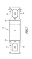
- a blank for a floor element inner part 24 can be seen.
- two inner wall elements 18 are arranged on a rear wall element 3.
- the inner wall elements 18 already have apertures 31.1.
- the inner wall elements 18 formed integrally with the rear wall element 3 by a punched blank.
- the floor element inner part 24 or the floor element 5 can also be formed from separate side wall elements 2 and separate rear wall elements 3.
- the inner wall elements 18 are folded at a folding edge 26 in each case by 90 °, and thus form an inner part of the side wall elements 2.
- the inner wall elements 18 have both above and below each have a recesses 19, 43 for later receiving the connecting straps 10.
- the upper recess 19 of an inner wall element 18 has the depth B, the lower recess 43 of an inner wall element 18 the depth C.
- the depth of the lower recess 43 corresponds at least to the height H of the connecting plates 10.
- the depth B of the upper recess 19 at least equal to the sum the dimension H of the connecting plate 10 and the thickness D of the connecting web 16.
- Fig. 8 shows a wall insert 20, which serves in each case as a reinforcement for an inner wall element 18 of the floor element inner part 24.
- the wall insert 20 also has top and bottom recesses 19, 43, which serve in the construction of the merchandise display 1 for receiving the connecting straps 10.
- the wall insert 20 has an opening 31.2, whose position corresponds to the position of the opening 31.1 in the floor element inner part 24.
- Fig. 9 shows a blank for a cover element 21 for a side wall element 2.
- the cover element 21 is formed by a Faltzulase, which is formed from two wall elements 44, 45, wherein both wall elements openings 31.3, 31.4 and the wall elements 44, 45 via a rebate area 46 with two fold lines 27, 28 are connected.
- One of the wall elements 45 has an upper recess 19 with a height A1 and a lower recess 43 with a height A2.
- the inner wall elements 18 of the blank in Fig. 7 folded by the folding edges 26 by 90 °.
- a wall insert 20 ( Fig. 9 ) is connected to an inner wall member 18, respectively.
- a cover element 21 is in turn folded and connected.
- the folding of the cover element 21 takes place about the two folded edges 27, 28, whereby the cover element assumes a U-shape.
- the arrangement in the embodiment shown is selected such that on the respective outer side of the side wall elements 2 thus formed the one Side of the cover member 21 is arranged, which contains no recesses 19, 43, thereon, the inner wall member 18 of the blank for the floor element ( Fig. 7 ), followed by the wall insert 20 is placed and as a conclusion, the bottom element 4 facing innermost material layer, the folded cover element 21 is located. Because of this arrangement, the apertures 31.1, 31.2, 31.3, 31.4 each come to lie on one another and give the impression of a through opening 31.
- the recesses 19, 43 form by the selected arrangement receiving pockets fourteenth
- the recesses 19 are larger than the recesses 43, which are below the blanks in later use. Comparing the respective recesses of the blank for the floor element inner part 24 ( Fig. 7 ) with the wall insert 20 and the cover element 21, it is noticeable that the blank for the floor element inner part 24 has lower recesses 19, 43 both at the top and at the bottom than the wall insert 20 and the cover element 21.
- the wall insert 20 and the cover element 21 have in the Embodiment same depths on. In other words, the depths B, F and A1 are selected such that B> F ⁇ A1 and that for the measures C, G and A2, C>G> A2.
- the receiving pockets 14 are not completely closed on the inside, that is to say on the material layer forming the inner surface of the side wall element 2, which faces the bottom support 4.
- the wall element 45 which forms the inner surface, has recesses 19, 43.
- the recesses 19, 43 may optionally be provided at the bottom, at the top, or both above and below.
- FIG. 1 Such a recess 19 can be seen on the inside of the side wall element 2 on the receiving pocket 14. If the wall element 45 forming the inner surface of the side wall element 2 only has a single recess 19, 43, then the recess has a depth A, calculated as the sum of the depths A1 and A2, which corresponds at least to the thickness D of the connecting web 16.
- the wall element 45 forming the inner surface of the side wall element 2 has a recess 19, 43 at the top and bottom, then the total height A added from the top height A1 and the bottom height A2 also corresponds at least to the thickness D of the connecting web 16.
- two Floor elements, each having a recess 19, 43 on the inner surface of the side wall member 2 at the top and bottom have stacked with their recesses 19 a window whose total height A, calculated from A1 and A2, at least the thickness D of the connecting web 16 corresponds. This ensures that the connecting web 16 is completely received in the recesses 19, 43 of the wall element 45 which forms the inner surface of the side wall element 2.
- the dimension A preferably corresponds to the thickness D of the connecting web 16, so that no gap remains on the inner surface between the side wall element 2 and the connecting web 16.
- the height E of the side wall elements 2 or floor elements 5 can be chosen freely. This allows any combination of floor elements 5 and side wall elements 2 of any height.
- the goods display 1 can thus be adapted to a variety of objects that are to be stored on the floor elements 4 of the goods display 1. Also, so that the overall height of the goods display 1 can be varied as desired.
- the recesses 19, 43 for forming the receiving pockets 14, regardless of the height E of the floor elements 5 and side wall elements 2 always the same dimensions to receive the connecting plates 10.
- the receiving pockets 14 are formed by recesses 19, 43 in a plurality of layers of material forming the side wall element 2. According to the invention, however, a recess 19 or 43 may be provided to form the receiving pocket 14 only in a single one of several layers of material.
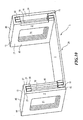
- the floor element 5 comprises two side wall elements 2 which are perpendicular to the rear wall element 3.
- Each of the side wall elements 2 in each case has an opening 31 which extends completely through the side wall elements 2.
- a rectangular opening with rounded edges was chosen as the shape.
- Both side wall elements 2 are each formed from a plurality of layers of material, which are glued together.
- the floor element inner part 24 As a basic element for the construction of the floor element 5, the floor element inner part 24 ( Fig. 7 ).
- the interior part 24th comprises a rear wall element 3 and two inner wall elements 18, which are each attached to one of the shorter sides of the rear wall element 3 with a hinge 26 formed by a fold line.
- the inner wall elements 18 are each folded on the hinge 26 by 90 °.
- a wall insert 20 (FIG. Fig. 8 ) glued.
- the cover element 21 (FIG. Fig. 9 ) is folded at the fold lines 27, 28 U-shaped and slipped over the already bonded composite of inner wall member 18 and wall insert 20 and glued so that the composite of inner wall member 18 and wall insert 20 is enclosed by the cover member 21.
- the cover element 21 forms a front edge 13, which is directed toward the interior of the floor element 5, as well as a folding area 46, which faces forward in the case of a merchandise display 1.
- the wall element 44 of the cover element 21 serves as an outwardly facing outer surface of the floor element 5
- the wall element 45 serves as an interior facing surface of the floor element 5.
- All elements of the side wall element 2 (18, 20, 21) are arranged such that the upper recesses 19 and the lower recesses 43 of the individual elements each come to rest next to one another, so that a receiving pocket 14 is formed on the side wall elements 2 at the top and bottom.
- Each of the elements of the side wall element 2 (18, 20, 21) is flush with the other elements at the top and bottom and forms a stacking surface 15 at the top and at the bottom of each of the side wall elements which touches the closest floor element 5 in the assembled state of the goods display 1.
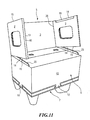
- Fig. 11 shows the base 6, which is fastened with T-shaped tongues 12 on the pallet 7.
- a floor element 5 is placed on the base 6, and placed such that tabs 29 engage in the receiving pockets 14.
- the plug-in tabs 29 are stamped into a folding blank for the base 6 and remain in the folding of the base 6 facing up. This arrangement allows the use of the receiving pockets 14 on the floor element 5, which are originally provided for receiving the connecting straps 10 of the floor elements 4.
- the merchandise display 1 is delivered to the user as a flattened kit comprising all elements of the merchandise display 1. All elements are suitably flattened, ie folded and can be constructed by the user usually without tools become.
- the kit is preferably delivered on a pallet, which also serves as a support for the base 6.
- plug-in tabs 29 are formed which point upwards.
- a floor element 5 is folded on the hinges 26 in its intended form and placed on the base 6.
- the tabs 29 engage in the receiving pockets 14 and provide a firm and stable connection.
- a bottom element 4 is also folded, whereby the safety strip 32 and connecting straps 10 form.
- the bottom element 4 is then placed on the floor element 5 and inserted with the lower connector strips 48 of the connecting straps 10 in the receiving pockets 14.
- the shape of the receiving pockets 14 ensure a horizontal fixation of the bottom element and thereby ensure the stability of the goods display 1.
- another floor element 5 is folded and placed on the upwardly facing headers 47 of the connecting plates 10 of the bottom element 4.
- the connecting straps 10 engage in the lower receiving pockets 14 of the floor element 5.
- further floor and floor elements can be placed on the goods display.
- the bottom element 4, as in the Fig. 12 and 13 can be formed according to another embodiment.
- the safety strips 32 are arranged on the longer sides 23 of the bottom element 4 and in each case one of the safety strips 32 extends from the storage surface 11 of the bottom element 4 viewed from up and down.
- the connectors formed as connecting tabs 10 are formed on the short sides 22 of the bottom member 4 such that they are formed by a user by folding and mating itself.
- the blank for the enveloping body 9.1 is designed such that it comprises subregions, each of which above, on the support surface 11 of the bottom member 4, on the short sides 22 each left and right survive, and extended sub-areas, each at the bottom of the Floor element 4 on the short sides 22 survive.
- the protruding parts form at the top, at the Depositing surface 11 on the short sides 22 of the bottom member 4 each have an upper tab portion 49 and at the bottom on the short sides 22 of the bottom member 4 also respectively a lower tab portion 50.
- the respectively on the short sides 22 of the bottom member 4 opposite upper tab members 49 and bottom tab members 50 may be formed by folding into a connecting tab 10.
- the upper insert part 49 is folded at a fold line 33 substantially 90 ° upwards and folded at a fold line 34 by 180 ° down.
- the lower plug-in flap part 50 is folded at the fold line 36 by 90 ° down and folded at the fold line 35 by 180 ° upwards.
- Upper plug-in tab part 49 and lower plug-in tab part 50 which are now on top of each other, have notches 51 into which the opposite plug-in tab part is inserted. Both plug-in flap parts 49, 50 are thereby fixed in position and together form a connecting plate 10.
- the bottom element 4 is configured point-symmetrical to the center of the shelf 11, ie with the upwards as below running security bars 32, it is possible for the user to install the floor element 4 in such a way that the safety strip 32 faces upwards so that, for example, fragile products are prevented from falling off the floor element 4, or the floor element 4 is installed such that the safety strip 32 points downwards and unobstructed access to the products is possible.
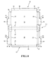
- the enveloping body 9 for the further embodiment of the bottom element 4 is replaced by a blank for the enveloping body 9.1 (FIG. Fig. 14 ) educated.
- the blank for the enveloping body 9.1 has two plate sections 59,60. These are connected to one another on their long side 23 via an adhesive portion 58 and a safety strip element 61. At the transition of the plate portion 59 to the adhesive portion 58 a fold line 52 is arranged. Also located between the adhesive portion 58 and the security bar member 61 is a further fold line 62 and between security bar member 61 and the plate portion 60 a further fold line 63. At the plate portion 60 is on the other long side 23, so opposite to the security bar element 31 via a fold line 64 an adhesive portion 65 arranged.
- respective lower plug-in flap parts 50 are fastened by way of fold lines 36, which have a further fold line 35 spaced parallel to the fold line 36.
- Both lower plug-in flap parts 50 each have an incision 51 in the middle of the side which lies parallel to the short side of the plate section 60.
- the incision 51 divides the boundary line of the lower plug-in flap parts 50 into a region which has a smaller distance from the fold line 36 and a region which, compared to this, has a greater distance from the fold line 36.
- a transition region 66 which begins at the incision 51 and at an angle to the boundary line of the section with the greater distance to the fold line 36 tapers.
- a safety bar member 68 is attached to the long side 23 opposite to the gluing portion 58.
- Upper plug-in flap parts 49 are respectively attached to the two short sides 22 of the plate section 59.
- a fold line 33 At the transition from plate portion 59 is a fold line 33, and parallel thereto on the upper Steckelschenenteil 49 another fold line 34.
- Parallel to the short side 22 of the plate portion 59 is located at the boundary line of the upper Steckelschenenteils 49, each parallel to the short side 22nd of the plate portion 59 extends an incision 51.
- Analogous to the lower plug-in flap parts 50 areas are also formed here, which have a greater distance from the fold line 33 and areas which have a smaller distance from the boundary line 33.
- the upper plug-in flap parts likewise comprise a transition region between the two regions, which begins at the cut 51 and ends at the region at a greater distance from the fold line 33.
- the safety edge members 68 and 61, as well as the adhesive portions 65 and 58 disposed on the plate portions 59, 60 each occupy the full length of the long sides 23.
- the blank for the enveloping body 9.1 becomes an enveloping body 9 ( Fig. 15 ) folded and glued in the manner of a package for the reinforcing core 8.
- at least sections of adhesive are applied to the adhesive section 58 and the security strip element with the plate section 60 fastened thereto is folded along the folding line 62 by 180 °.
- the security strip element 61 comes to lie at least in some areas on the adhesive portion 58 and glued to this.
- Now adhesive is at least partially applied to the adhesive portion 65 and also folded at the fold line 64 by 180 °, so that the adhesive portion 65 comes to lie at least on portions of the safety edge member 68 and glued to this.
- an adhesive may be used for both adhesive portions 58,65 ordinary, or conventional adhesive for cardboard, paper or the like. The use of double-sided tape would be conceivable.
- the enveloping body 9 is now in a favorable flat for transportation transport, which is why the transport is preferably carried out in this position.
- the enveloping body 9 In order to form a bottom element 4 from this transport position of the enveloping body 9, the enveloping body 9 must be transferred into a position of use.
- the security strips 32 which are still parallel to the planes of the plate sections 59, 60 by the adhesive sections 58 and the safety strip element 61, as well as the adhesive section 65 and the safety strip element 68, must be brought into a rectangular position relative to the plate sections 59, 60 for this purpose become.
- a cavity 57 which is accessible from the short sides 22 of the plate sections 59, 60, forms between the plate sections 59, 60.
- the enveloping body 9 thus forms a circumferential lateral surface around the cavity 57.
- a reinforcing core 8 is inserted and completely received therein.
- the upper and lower plug-in flap parts 49, 50 are now folded at the fold lines 33, 34, 35 and 36 and, as described above, put together.
- the cavity 57 is thereby closed and the connecting straps 10 are formed.
- the bottom element 4 can now be used for the construction of a merchandise display 1.
- one of the plate sections 59, 60 forms the storage surface 11.
- the blank can also be made in two or more parts.
- a simple way of making the blank in two parts is to cut the blank 9.1 (FIG. Fig. 14 ) at fold line 62. This gives two identical blanks which can be glued over the adhesive portions 58, 65 to form an enveloping body 9.
- the further assembly of the bottom element 4 corresponds to the previously described assembly of the one-piece blank 9.1.
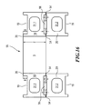
- FIG. 16 Another possibility for forming a floor element inner part 55 is in Fig. 16 shown and is to form the wall inserts 20 to the known floor element inner part 24.
- the wall inserts 20 are connected via fold lines 54 with the floor element inner part 55, and must be folded for assembly only upwards.
- the openings 31.1, 31.2 are positioned so that they come to lie after folding around fold line 54 to each other and produce a continuous opening.
- the wall inserts 20 also have recesses 19, which after folding around fold line 54 substantially coincide with the recesses 19 of the floor element 55.
- a recess 56 is provided between the floor element inner part and the molded wall inserts 20.
- the measure of the total height of the recesses 56 is made up of the height of the portion C, this is the measure of the recess from the inner wall member 18 to the fold line 52 and the dimension G, the distance from the fold line 54 to the Wandeinalge 20.
- the thus formed Floor element inner part 55 can be connected in its folded state with the cover element 21 in the usual way, as described above, to a floor element 5.
- the floor elements 5 above and below each have identical receiving pockets 14.
- This allows installation of the floor elements 5, without having to pay attention to which of the stacking surfaces 15 above, or has to lie down.
- This facilitates the construction of the display and makes the overall design more flexible.
- the recesses 19, 43 of all receiving pockets 14 are identical.
- the apertures 31 are each introduced horizontally and vertically in the middle.
Landscapes
- Cartons (AREA)
Priority Applications (1)
| Application Number | Priority Date | Filing Date | Title |
|---|---|---|---|
| EP08002046A EP2084997A1 (fr) | 2008-02-04 | 2008-02-04 | Présentation de marchandises |
Applications Claiming Priority (1)
| Application Number | Priority Date | Filing Date | Title |
|---|---|---|---|
| EP08002046A EP2084997A1 (fr) | 2008-02-04 | 2008-02-04 | Présentation de marchandises |
Publications (1)
| Publication Number | Publication Date |
|---|---|
| EP2084997A1 true EP2084997A1 (fr) | 2009-08-05 |
Family
ID=39563292
Family Applications (1)
| Application Number | Title | Priority Date | Filing Date |
|---|---|---|---|
| EP08002046A Withdrawn EP2084997A1 (fr) | 2008-02-04 | 2008-02-04 | Présentation de marchandises |
Country Status (1)
| Country | Link |
|---|---|
| EP (1) | EP2084997A1 (fr) |
Cited By (2)
| Publication number | Priority date | Publication date | Assignee | Title |
|---|---|---|---|---|
| DE102009019543B3 (de) * | 2009-04-30 | 2010-12-09 | Gustav Stabernack Gmbh | Modulares mehrstöckiges Warendisplay |
| DE202014102903U1 (de) * | 2014-06-25 | 2015-10-02 | Gissler & Pass Gmbh | Trayregal |
Citations (5)
| Publication number | Priority date | Publication date | Assignee | Title |
|---|---|---|---|---|
| DE4314682A1 (de) * | 1993-05-04 | 1994-11-10 | Cde Commerce Display Norbert E | Verkaufsaufsteller in Form eines Turmes |
| DE29610442U1 (de) | 1996-06-14 | 1996-08-29 | CDE Commerce Display Norbert Eichler GmbH, 22525 Hamburg | Warenträger für Verkaufsaufsteller |
| DE29622521U1 (de) | 1996-12-28 | 1997-02-27 | FULDA VERPACKUNG STABERNACK JR GMBH, 36043 Fulda | Displayregal |
| US5984120A (en) | 1998-03-20 | 1999-11-16 | Stone Container Corporation | Point-of-purchase display system and method for formation thereof |
| GB2359801A (en) | 2000-01-20 | 2001-09-05 | Crp Print & Packaging Ltd | A display container |
-
2008
- 2008-02-04 EP EP08002046A patent/EP2084997A1/fr not_active Withdrawn
Patent Citations (5)
| Publication number | Priority date | Publication date | Assignee | Title |
|---|---|---|---|---|
| DE4314682A1 (de) * | 1993-05-04 | 1994-11-10 | Cde Commerce Display Norbert E | Verkaufsaufsteller in Form eines Turmes |
| DE29610442U1 (de) | 1996-06-14 | 1996-08-29 | CDE Commerce Display Norbert Eichler GmbH, 22525 Hamburg | Warenträger für Verkaufsaufsteller |
| DE29622521U1 (de) | 1996-12-28 | 1997-02-27 | FULDA VERPACKUNG STABERNACK JR GMBH, 36043 Fulda | Displayregal |
| US5984120A (en) | 1998-03-20 | 1999-11-16 | Stone Container Corporation | Point-of-purchase display system and method for formation thereof |
| GB2359801A (en) | 2000-01-20 | 2001-09-05 | Crp Print & Packaging Ltd | A display container |
Cited By (3)
| Publication number | Priority date | Publication date | Assignee | Title |
|---|---|---|---|---|
| DE102009019543B3 (de) * | 2009-04-30 | 2010-12-09 | Gustav Stabernack Gmbh | Modulares mehrstöckiges Warendisplay |
| EP2245962A3 (fr) * | 2009-04-30 | 2011-11-30 | Gustav Stabernack GmbH | Affichage de marchandises modulaire à plusieurs étages |
| DE202014102903U1 (de) * | 2014-06-25 | 2015-10-02 | Gissler & Pass Gmbh | Trayregal |
Similar Documents
| Publication | Publication Date | Title |
|---|---|---|
| CH694682A5 (de) | Display aus einem Staender und eingelegten Trays. | |
| DE3909898C2 (fr) | ||
| DE102009019543B3 (de) | Modulares mehrstöckiges Warendisplay | |
| DE102009057370B4 (de) | Displayregal für eine Zweitplatzierung von Waren | |
| DE102004003246B4 (de) | Sockel und Zuschnitt hierfür | |
| DE10245241A1 (de) | Manschettenartige Faltschachtel | |
| DE202020106165U1 (de) | Stapelbarer Warenträger | |
| EP3925906A1 (fr) | Emballage pour pare-choc | |
| DE102013211939B4 (de) | Faltregalsystem und Verfahren zu dessen Herstellung und Aufstellung | |
| EP4072954A1 (fr) | Boîte pliante | |
| DE3818861C1 (fr) | ||
| DE102006056467B4 (de) | Verfahren zur Herstellung eines Warentrays | |
| EP3018062A1 (fr) | Boîte pliante en tant qu'objet de décoration | |
| EP3909475B1 (fr) | Socle d'affichage, découpe et procédé de construction du socle | |
| DE29904104U1 (de) | Regalmodul als Faltelement und aus Regalmodulen hergestelltes Regal | |
| DE19716735A1 (de) | Verkaufsaufsteller | |
| DE102008029217B4 (de) | Trayverpackung, insbesondere für schwere Produkte | |
| DE202006009756U1 (de) | Verkaufsmodul, Display-Set und Zuschnitt-Set | |
| DE9103961U1 (de) | Tray | |
| DE102021131938A1 (de) | Präsentationsständer | |
| DE29614879U1 (de) | Display | |
| DE102008035528A1 (de) | Schachtel zum Aufnehmen von Schalen mit Inhalt | |
| DE29514747U1 (de) | Verkaufsaussteller | |
| DE202006007160U1 (de) | Transport- und Verkaufsverpackung mit Warenvorschubsystem | |
| DE19534000A1 (de) | Verkaufsaussteller |
Legal Events
| Date | Code | Title | Description |
|---|---|---|---|
| PUAI | Public reference made under article 153(3) epc to a published international application that has entered the european phase |
Free format text: ORIGINAL CODE: 0009012 |
|
| AK | Designated contracting states |
Kind code of ref document: A1 Designated state(s): AT BE BG CH CY CZ DE DK EE ES FI FR GB GR HR HU IE IS IT LI LT LU LV MC MT NL NO PL PT RO SE SI SK TR |
|
| AX | Request for extension of the european patent |
Extension state: AL BA MK RS |
|
| 17P | Request for examination filed |
Effective date: 20100129 |
|
| AKX | Designation fees paid |
Designated state(s): AT BE BG CH CY CZ DE DK EE ES FI FR GB GR HR HU IE IS IT LI LT LU LV MC MT NL NO PL PT RO SE SI SK TR |
|
| 17Q | First examination report despatched |
Effective date: 20110404 |
|
| GRAP | Despatch of communication of intention to grant a patent |
Free format text: ORIGINAL CODE: EPIDOSNIGR1 |
|
| STAA | Information on the status of an ep patent application or granted ep patent |
Free format text: STATUS: THE APPLICATION IS DEEMED TO BE WITHDRAWN |
|
| 18D | Application deemed to be withdrawn |
Effective date: 20120901 |