EP2085103A1 - Infusionsgerät - Google Patents
Infusionsgerät Download PDFInfo
- Publication number
- EP2085103A1 EP2085103A1 EP08001688A EP08001688A EP2085103A1 EP 2085103 A1 EP2085103 A1 EP 2085103A1 EP 08001688 A EP08001688 A EP 08001688A EP 08001688 A EP08001688 A EP 08001688A EP 2085103 A1 EP2085103 A1 EP 2085103A1
- Authority
- EP
- European Patent Office
- Prior art keywords
- pump
- infusion device
- locking
- stop facility
- infusion
- Prior art date
- Legal status (The legal status is an assumption and is not a legal conclusion. Google has not performed a legal analysis and makes no representation as to the accuracy of the status listed.)
- Granted
Links
Images
Classifications
-
- A—HUMAN NECESSITIES
- A61—MEDICAL OR VETERINARY SCIENCE; HYGIENE
- A61M—DEVICES FOR INTRODUCING MEDIA INTO, OR ONTO, THE BODY; DEVICES FOR TRANSDUCING BODY MEDIA OR FOR TAKING MEDIA FROM THE BODY; DEVICES FOR PRODUCING OR ENDING SLEEP OR STUPOR
- A61M5/00—Devices for bringing media into the body in a subcutaneous, intra-vascular or intramuscular way; Accessories therefor, e.g. filling or cleaning devices, arm-rests
- A61M5/14—Infusion devices, e.g. infusing by gravity; Blood infusion; Accessories therefor
- A61M5/142—Pressure infusion, e.g. using pumps
- A61M5/14212—Pumping with an aspiration and an expulsion action
- A61M5/14232—Roller pumps
-
- F—MECHANICAL ENGINEERING; LIGHTING; HEATING; WEAPONS; BLASTING
- F04—POSITIVE - DISPLACEMENT MACHINES FOR LIQUIDS; PUMPS FOR LIQUIDS OR ELASTIC FLUIDS
- F04B—POSITIVE-DISPLACEMENT MACHINES FOR LIQUIDS; PUMPS
- F04B43/00—Machines, pumps, or pumping installations having flexible working members
- F04B43/0009—Special features
- F04B43/0081—Special features systems, control, safety measures
-
- F—MECHANICAL ENGINEERING; LIGHTING; HEATING; WEAPONS; BLASTING
- F04—POSITIVE - DISPLACEMENT MACHINES FOR LIQUIDS; PUMPS FOR LIQUIDS OR ELASTIC FLUIDS
- F04B—POSITIVE-DISPLACEMENT MACHINES FOR LIQUIDS; PUMPS
- F04B43/00—Machines, pumps, or pumping installations having flexible working members
- F04B43/12—Machines, pumps, or pumping installations having flexible working members having peristaltic action
- F04B43/1253—Machines, pumps, or pumping installations having flexible working members having peristaltic action by using two or more rollers as squeezing elements, the rollers moving on an arc of a circle during squeezing
-
- A—HUMAN NECESSITIES
- A61—MEDICAL OR VETERINARY SCIENCE; HYGIENE
- A61M—DEVICES FOR INTRODUCING MEDIA INTO, OR ONTO, THE BODY; DEVICES FOR TRANSDUCING BODY MEDIA OR FOR TAKING MEDIA FROM THE BODY; DEVICES FOR PRODUCING OR ENDING SLEEP OR STUPOR
- A61M2205/00—General characteristics of the apparatus
- A61M2205/27—General characteristics of the apparatus preventing use
- A61M2205/276—General characteristics of the apparatus preventing use preventing unwanted use
-
- A—HUMAN NECESSITIES
- A61—MEDICAL OR VETERINARY SCIENCE; HYGIENE
- A61M—DEVICES FOR INTRODUCING MEDIA INTO, OR ONTO, THE BODY; DEVICES FOR TRANSDUCING BODY MEDIA OR FOR TAKING MEDIA FROM THE BODY; DEVICES FOR PRODUCING OR ENDING SLEEP OR STUPOR
- A61M2205/00—General characteristics of the apparatus
- A61M2205/33—Controlling, regulating or measuring
- A61M2205/3365—Rotational speed
Definitions
- the invention refers to an infusion device comprising a pump and an electronic controller for controlling the pump.
- Such infusion devices are used to deliver insulin or other medication to a patient.
- the controller may comprise a microprocessor that monitors motor current consumption to detect a malfunction or utilise sensors for occlusion detection or the like.
- a malfunction of the controller itself for example a direct short from the power source to the pump motor, might cause the pump motor to drive continuously and deliver all the medication contained in the infusion system over a short period and thereby cause severe over delivery.
- solenoid actuators or stepper motors to drive the infusion pump.
- solenoid actuators or stepper motors are rather expensive and not nearly as energy efficient as DC motors.
- Large energy consumption is a serious disadvantage as larger and heavier batteries are required which is incompatible with the standard design objective to make infusion devices small, compact and light-weight.
- An infusion device has a mechanical stop facility for stopping the pump by mechanically blocking pump motion.
- a mechanical stop facility can be used to reliably stop an infusion even if the pump motor is still powered due to a failure of the electronic controller.
- the stop facility blocks pump motion by positive locking, although friction locking may also be used.
- An especially simple and yet reliable way of stopping an infusion is a stop facility that stops the pump by mechanically locking a driveshaft, e. g. by means of a locking plate.
- the stop facility is configured such that it periodically requires resetting by the controller to continue an infusion.
- resetting of the mechanical stop facility may comprise moving a locking member out of an engagement position.
- a stop facility that comprises a reversing transmission and two limit stops which periodically require a reversing of rotation. Such a stop facility may be reset by reversing the direction of rotation of the reversing transmission
- a stop facility that periodically requires resetting by the controller to continue an infusion ensures that in the case of a failure of the controller pump motion is blocked after a rather short time as a faulty controller will fail to reset the stop facility. Therefore, over dosing is limited to the amount that can be infused in the time period between resets, i. e. the time between the last reset and the stopping action of the stop facility when the required reset does not occur.
- the stop facility may block pump motion by engaging a rotating mechanical element, e.g. a protrusion or a recess, for positive locking.
- the stop facility comprises a spring biased locking member.
- the spring forces the locking member into a positive locking engagement with a suitable counterpart, a recess for example.
- the counterpart may be fixed to the drive shaft or some other rotating part of the pump.
- the locking member has to disengage which may be done by an actuator, e.g. a solenoid, controlled by the electronic controller.
- the stop facility comprises at least two locking members which alternately block pump motion. Resetting the stop facility may then be done by moving one of the locking members to disengage from locking engagement which activates at least one other locking member so that it will block pump motion after a preset period.
- an actuator may be used for resetting locking elements in such a way that the actuator, e.g. a winding core, moves between two positions and thereby always pushes either one of two locking members away from a rotating mechanical locking element like a locking plate.
- the locking members may be spring biased to readily engage the locking element.
- the pump is a peristaltic pump.
- Peristaltic pumps enable a precise dosing even at very low infusion rates.
- a rotary peristaltic pump although other pumps may also be used.
- the peristaltic pump comprises a rotor with at least four, preferably at least five, annularly arranged compressing elements for acting in peristaltic fashion on a flexible tube conveying a liquid to be infused. Then, at least one of the uniformly distributed compressing elements will always reliably compress the tube and thereby close it. Hence, whenever the pump is stopped, no liquid flow can occur.
- the pump motor is a DC motor as such motors are efficient and inexpensive although other motors may also be used.
- the stop facility causes disconnection of the motor if it is not reset within a preset time.
- the stop facility may upon blocking pumping motion actuate a time delayed switch which will disconnect the motor if no corrective action is taken by the controller within the preset time.
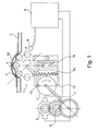
- FIG. 1 shows schematically an embodiment of an infusion device.
- the infusion device comprises a peristaltic pump 1 acting on a flexible tube 2 to pump a liquid to be infused, for example insulin.
- the peristaltic pump 1 has a rotor 3 with more than four, especially more than five compressing elements 4 which act in peristaltic fashion on the flexible tube 2 supported by an arcuate pump bed 10 . Stopping the rotor 3 blocks liquid flowing through to the tube 2 as there is always at least one compressing element 4 pressing on the tube 2 and thereby closing it.
- the rotor 3 of the peristaltic pump 1 has eight compressing elements 4.
- the rotor 3 of the peristaltic pump 1 is driven by a DC-Motor 5 via a transmission 6 and a drive shaft 7.
- the DC motor 5 is controlled by an electronic controller 8, for example a microprocessor, that monitors by means of a sensor 9 rotation of the rotor 3 and thereby the infusion rate.
- the infusion device shown in figure 1 comprises a mechanical stop facility for stopping the pump 1 by mechanically blocking pump motion.
- the stop facility comprises a locking plate 11, which is connected to the drive shaft 7, and a locking member 12 which interacts with the locking plate 11.
- the locking member 12 engages a recess of the locking plate 11.
- the locking member 12 is biased by spring 13 against the locking plate 11.
- the controller 8 resets the stop facility by means of an actuator 14, for example a solenoid.
- the actuator 14 moves the locking member 12 out of its engagement position in which it protrudes into the recess of the locking plate 11.
- the locking plate 11 has only one recess and the stop facility comprises only one locking member 12, such a resetting is required every full turn of the drive shaft 7.
- two locking members 12 which alternately block pump motion are arranged opposite each other such that the stop facility has to be reset every half turn of the drive shaft 7.
- the locking members 12 there is only one recess to be engaged by the locking members 12.
- a plurality of locking elements e.g. recesses of a locking plate. Then the stop facility has to be reset more often. If two locking members 12 are to be used alternately, the locking elements, e.g. recesses, should be arranged in such a way that the locking members 12 cannot engage at the same time.
- Both locking members 12 are reset by the same actuator 14. Resetting the stop facility by moving one of the locking members 12 to disengage from positive locking engagement activates at least one other locking member 12 so that it will block pump motion after a preset period which is in the example shown a half turn of the locking plate. Activation of a locking member 12 is achieved by movement of the actuator 14 which by moving to disengage one locking member 12 frees the other so that it can engage a rotating locking element, which is in the example shown a recess of the locking plate 11.
- Disconnection of the drive motor 5 may be achieved by a switch which may be actuated by movement of the locking member 12, for example.
- a switch which may be actuated by movement of the locking member 12, for example.
- a switch is acts temporally delayed after locking of the pump 1 to ensure that the drive motor 7 is only disconnected in case of a failure of the controller 8, i.e. when the stop facility is not reset with a predetermined time, for example a few seconds or less.
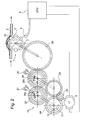
- FIG 2 shows schematically another embodiment of an ambulatory infusion device.
- This device also comprises a rotary peristaltic pump 1 which is driven via a drive shaft 7 by a DC-Motor 5 controlled by a controller 8.
- the infusion devices shown in figures 1 and 2 differ with respect to the stop facility for stopping the pump by mechanically blocking pump motion.
- the stop facility of the device shown in figure 2 comprises a reversing transmission 15 which connects the motor 5 to the drive shaft 7.
- the reversing transmission comprises two parallel shafts 21, 22 which rotate in opposite directions.
- the shafts are driven by the motor 5 via a gear wheel 23 which meshes with gear wheel 24 fixed to shaft 21 and gear wheel 25 fixed to shaft 22.
- Gear wheels 24 and 25 are arranged on opposite sides of gear wheel 23 such that they rotate in opposite directions.
- a ratchet and pawl mechanism 26a is fixed to shafts 21.
- the ratchet and pawl mechanism 26a interacts with a gear wheel 27 which can turn relative to shaft 21.
- a gear wheel 27 which can turn relative to shaft 21.
- ratchet and pawl mechanism 26b interacts with a gear wheel 28 which can turn relative to shaft 22.
- the ratchet and pawl mechanisms 26a and 26b are active in opposite direction.
- the ratchet and pawl mechanism 26b transmits counter-clockwise rotation of the shaft 22 to the gear wheel 28, whereas clockwise rotation of the shaft 22 is not transmitted to the gear wheel 28.
- the ratchet and pawl mechanisms 26a, 26b ensure that gear wheel 29 and therefore the drive shaft 7 always rotate in the same direction regardless of the directions of rotation of shafts 21, 22 and gear wheel 23.
- the reversing transmission drives the drive shaft 7 always in the same direction. Hence, resetting of the stop facility by reversing rotation causes the drive shaft to continue to turn and thereby to pump liquid through the tube 2 in the direction of the arrows shown.
- gear wheel 24 of the reversing transmission 15 has a locking structure, for example a groove 17, which is engaged by a pin 18.
- a locking structure for example a groove 17, which is engaged by a pin 18.
- the pin 18 moves along the locking structure 17 until it reaches a limit stop, in the example shown an end of the groove 17, which acts as a locking member. Once this happens, an infusion is stopped as further pump action, i.e. further rotation of the gear wheel 24 in the same direction, is blocked by the pin 18 engaging the limit stop.
- the controller 8 has to reset the locking mechanism which in the example shown is done by reversing the direction of rotation of the motor 5. Reversing rotation causes the pin 18 to move back along the locking structure 17 until it reaches the limit stop at the other end of the groove. Then the motor 5 has to change direction of rotation again.
- the reversing transmission 15 drives the drive shaft 7 always in the same direction. Hence, resetting of the stop facility by reversing rotation causes the drive shaft to continue to turn and thereby to pump liquid through the tube 2 in the direction of the arrows shown.
Landscapes
- Engineering & Computer Science (AREA)
- Health & Medical Sciences (AREA)
- Mechanical Engineering (AREA)
- General Engineering & Computer Science (AREA)
- Hematology (AREA)
- Anesthesiology (AREA)
- Biomedical Technology (AREA)
- Heart & Thoracic Surgery (AREA)
- Vascular Medicine (AREA)
- Life Sciences & Earth Sciences (AREA)
- Animal Behavior & Ethology (AREA)
- General Health & Medical Sciences (AREA)
- Public Health (AREA)
- Veterinary Medicine (AREA)
- Infusion, Injection, And Reservoir Apparatuses (AREA)
- Control Of Positive-Displacement Pumps (AREA)
- Acyclic And Carbocyclic Compounds In Medicinal Compositions (AREA)
Priority Applications (10)
| Application Number | Priority Date | Filing Date | Title |
|---|---|---|---|
| DK08001688.4T DK2085103T3 (da) | 2008-01-30 | 2008-01-30 | Infusionsindretning |
| ES08001688T ES2344132T3 (es) | 2008-01-30 | 2008-01-30 | Dispositivo de infusion. |
| EP08001688A EP2085103B1 (de) | 2008-01-30 | 2008-01-30 | Infusionsgerät |
| DE602008001240T DE602008001240D1 (de) | 2008-01-30 | 2008-01-30 | Infusionsgerät |
| AT08001688T ATE467434T1 (de) | 2008-01-30 | 2008-01-30 | Infusionsgerät |
| CA002649976A CA2649976A1 (en) | 2008-01-30 | 2009-01-16 | Infusion device |
| JP2009008424A JP2009178548A (ja) | 2008-01-30 | 2009-01-19 | 輸液装置 |
| CN2009100099675A CN101496922B (zh) | 2008-01-30 | 2009-01-24 | 输注装置 |
| US12/362,795 US8323245B2 (en) | 2008-01-30 | 2009-01-30 | Infusion device and method |
| HK10100831.1A HK1137155B (en) | 2008-01-30 | 2010-01-26 | Infusion device |
Applications Claiming Priority (1)
| Application Number | Priority Date | Filing Date | Title |
|---|---|---|---|
| EP08001688A EP2085103B1 (de) | 2008-01-30 | 2008-01-30 | Infusionsgerät |
Publications (2)
| Publication Number | Publication Date |
|---|---|
| EP2085103A1 true EP2085103A1 (de) | 2009-08-05 |
| EP2085103B1 EP2085103B1 (de) | 2010-05-12 |
Family
ID=39473630
Family Applications (1)
| Application Number | Title | Priority Date | Filing Date |
|---|---|---|---|
| EP08001688A Active EP2085103B1 (de) | 2008-01-30 | 2008-01-30 | Infusionsgerät |
Country Status (9)
| Country | Link |
|---|---|
| US (1) | US8323245B2 (de) |
| EP (1) | EP2085103B1 (de) |
| JP (1) | JP2009178548A (de) |
| CN (1) | CN101496922B (de) |
| AT (1) | ATE467434T1 (de) |
| CA (1) | CA2649976A1 (de) |
| DE (1) | DE602008001240D1 (de) |
| DK (1) | DK2085103T3 (de) |
| ES (1) | ES2344132T3 (de) |
Families Citing this family (4)
| Publication number | Priority date | Publication date | Assignee | Title |
|---|---|---|---|---|
| US8612055B2 (en) * | 2010-04-16 | 2013-12-17 | Medtronic, Inc. | System and method for delivering a therapeutic agent according to default infusion schedule |
| US9940440B2 (en) | 2011-04-28 | 2018-04-10 | Medtronic, Inc. | Detecting and responding to software and hardware anomalies in a fluid delivery system |
| KR101725419B1 (ko) * | 2015-06-09 | 2017-04-11 | 서강대학교산학협력단 | 약물 주입을 위한 연동장치 |
| US10492141B2 (en) | 2015-11-17 | 2019-11-26 | Tandem Diabetes Care, Inc. | Methods for reduction of battery usage in ambulatory infusion pumps |
Citations (5)
| Publication number | Priority date | Publication date | Assignee | Title |
|---|---|---|---|---|
| DE3636948C1 (de) * | 1986-10-30 | 1987-05-07 | Braun Melsungen Ag | Federaufzugsgetriebe fuer das Laufwerk eines Geraetes mit Durchlaufsicherung |
| US4828551A (en) * | 1987-10-13 | 1989-05-09 | Gertler Robert A | Patient controlled analgesia apparatus |
| EP0369322A2 (de) * | 1988-11-12 | 1990-05-23 | Fresenius AG | Spritzenpumpe |
| GB2308067A (en) * | 1995-12-14 | 1997-06-18 | Smiths Industries Plc | Fluid Administration Apparatus |
| WO2006078817A2 (en) | 2005-01-21 | 2006-07-27 | Medrad, Inc. | Injectors, injector systems and methods for injecting fluids |
Family Cites Families (7)
| Publication number | Priority date | Publication date | Assignee | Title |
|---|---|---|---|---|
| US3685371A (en) * | 1971-04-05 | 1972-08-22 | James W Crooks | Reversing transmission |
| US4676122A (en) * | 1984-06-15 | 1987-06-30 | Daltex Medical Sciences, Inc. | Fail-safe mechanical drive for syringe |
| US5176646A (en) * | 1991-02-19 | 1993-01-05 | Takayuki Kuroda | Motorized syringe pump |
| CA2434731C (en) | 2001-02-22 | 2010-01-26 | Insulet Corporation | Modular infusion device and method |
| US20020071225A1 (en) | 2001-04-19 | 2002-06-13 | Minimed Inc. | Direct current motor safety circuits for fluid delivery systems |
| US20050238507A1 (en) | 2002-04-23 | 2005-10-27 | Insulet Corporation | Fluid delivery device |
| US8147451B2 (en) * | 2005-02-11 | 2012-04-03 | Stryker Corporation | Reprogrammable fluid delivery system and method of use |
-
2008
- 2008-01-30 AT AT08001688T patent/ATE467434T1/de not_active IP Right Cessation
- 2008-01-30 EP EP08001688A patent/EP2085103B1/de active Active
- 2008-01-30 DE DE602008001240T patent/DE602008001240D1/de active Active
- 2008-01-30 ES ES08001688T patent/ES2344132T3/es active Active
- 2008-01-30 DK DK08001688.4T patent/DK2085103T3/da active
-
2009
- 2009-01-16 CA CA002649976A patent/CA2649976A1/en not_active Abandoned
- 2009-01-19 JP JP2009008424A patent/JP2009178548A/ja active Pending
- 2009-01-24 CN CN2009100099675A patent/CN101496922B/zh active Active
- 2009-01-30 US US12/362,795 patent/US8323245B2/en active Active
Patent Citations (5)
| Publication number | Priority date | Publication date | Assignee | Title |
|---|---|---|---|---|
| DE3636948C1 (de) * | 1986-10-30 | 1987-05-07 | Braun Melsungen Ag | Federaufzugsgetriebe fuer das Laufwerk eines Geraetes mit Durchlaufsicherung |
| US4828551A (en) * | 1987-10-13 | 1989-05-09 | Gertler Robert A | Patient controlled analgesia apparatus |
| EP0369322A2 (de) * | 1988-11-12 | 1990-05-23 | Fresenius AG | Spritzenpumpe |
| GB2308067A (en) * | 1995-12-14 | 1997-06-18 | Smiths Industries Plc | Fluid Administration Apparatus |
| WO2006078817A2 (en) | 2005-01-21 | 2006-07-27 | Medrad, Inc. | Injectors, injector systems and methods for injecting fluids |
Also Published As
| Publication number | Publication date |
|---|---|
| ATE467434T1 (de) | 2010-05-15 |
| HK1137155A1 (en) | 2010-07-23 |
| CA2649976A1 (en) | 2009-07-30 |
| EP2085103B1 (de) | 2010-05-12 |
| CN101496922A (zh) | 2009-08-05 |
| DK2085103T3 (da) | 2010-09-06 |
| US8323245B2 (en) | 2012-12-04 |
| ES2344132T3 (es) | 2010-08-18 |
| US20090192461A1 (en) | 2009-07-30 |
| JP2009178548A (ja) | 2009-08-13 |
| CN101496922B (zh) | 2011-11-16 |
| DE602008001240D1 (de) | 2010-06-24 |
Similar Documents
| Publication | Publication Date | Title |
|---|---|---|
| US12246162B2 (en) | Rotational metering pump for medication patch | |
| EP1874390B1 (de) | Flüssigkeitsabgabevorrichtung | |
| JP6628796B2 (ja) | 流動制御装置とこれを動作させる方法 | |
| US7367358B2 (en) | Medical fluid delivery system and method relating to the same | |
| CN102149417B (zh) | 给药单元和包括给药单元的移动式输注装置 | |
| EP2085103B1 (de) | Infusionsgerät | |
| JP2015530153A5 (de) | ||
| WO2008139459A1 (en) | Methods and apparatus for monitoring rotation of an infusion pump driving mechanism | |
| AU2019251796B2 (en) | Method and devices for delivering insulin | |
| EP2072072B1 (de) | Verfahren und Vorrichtung zur Mikrodosierung einer Flüssigkeit | |
| US12156988B2 (en) | Methods and devices for occlusion detection using actuator sensors | |
| EP3662574B1 (de) | Antriebssteuerung und verstopfungsdetektion in ambulanter infusionsvorrichtung | |
| RU2736607C2 (ru) | Блок привода клапана с исполнительным механизмом из сплава с памятью формы | |
| HK1137155B (en) | Infusion device | |
| EP4271446B1 (de) | Diskreter dosissteuerungs- und überdosisverhinderungsmechanismus | |
| EP1848471A1 (de) | System zur abgabe eines medizinischen fluids und darauf bezogenes verfahren | |
| KR20250125400A (ko) | 약물 전달 디바이스 구동 메커니즘 | |
| JP7730831B2 (ja) | 輸液ポンプの圧力変調モータトルク | |
| EP4516338B1 (de) | Arzneimittelabgabevorrichtung | |
| WO2005011082A2 (en) | Drive motor transmission system |
Legal Events
| Date | Code | Title | Description |
|---|---|---|---|
| PUAI | Public reference made under article 153(3) epc to a published international application that has entered the european phase |
Free format text: ORIGINAL CODE: 0009012 |
|
| AK | Designated contracting states |
Kind code of ref document: A1 Designated state(s): AT BE BG CH CY CZ DE DK EE ES FI FR GB GR HR HU IE IS IT LI LT LU LV MC MT NL NO PL PT RO SE SI SK TR |
|
| AX | Request for extension of the european patent |
Extension state: AL BA MK RS |
|
| 17P | Request for examination filed |
Effective date: 20090916 |
|
| 17Q | First examination report despatched |
Effective date: 20091007 |
|
| GRAP | Despatch of communication of intention to grant a patent |
Free format text: ORIGINAL CODE: EPIDOSNIGR1 |
|
| GRAS | Grant fee paid |
Free format text: ORIGINAL CODE: EPIDOSNIGR3 |
|
| GRAA | (expected) grant |
Free format text: ORIGINAL CODE: 0009210 |
|
| AKX | Designation fees paid |
Designated state(s): AT BE BG CH CY CZ DE DK EE ES FI FR GB GR HR HU IE IS IT LI LT LU LV MC MT NL NO PL PT RO SE SI SK TR |
|
| AK | Designated contracting states |
Kind code of ref document: B1 Designated state(s): AT BE BG CH CY CZ DE DK EE ES FI FR GB GR HR HU IE IS IT LI LT LU LV MC MT NL NO PL PT RO SE SI SK TR |
|
| REG | Reference to a national code |
Ref country code: GB Ref legal event code: FG4D |
|
| REG | Reference to a national code |
Ref country code: CH Ref legal event code: EP |
|
| REG | Reference to a national code |
Ref country code: IE Ref legal event code: FG4D |
|
| REF | Corresponds to: |
Ref document number: 602008001240 Country of ref document: DE Date of ref document: 20100624 Kind code of ref document: P |
|
| REG | Reference to a national code |
Ref country code: NL Ref legal event code: T3 Ref country code: ES Ref legal event code: FG2A Ref document number: 2344132 Country of ref document: ES Kind code of ref document: T3 |
|
| REG | Reference to a national code |
Ref country code: DK Ref legal event code: T3 |
|
| LTIE | Lt: invalidation of european patent or patent extension |
Effective date: 20100512 |
|
| PG25 | Lapsed in a contracting state [announced via postgrant information from national office to epo] |
Ref country code: NO Free format text: LAPSE BECAUSE OF FAILURE TO SUBMIT A TRANSLATION OF THE DESCRIPTION OR TO PAY THE FEE WITHIN THE PRESCRIBED TIME-LIMIT Effective date: 20100812 Ref country code: LT Free format text: LAPSE BECAUSE OF FAILURE TO SUBMIT A TRANSLATION OF THE DESCRIPTION OR TO PAY THE FEE WITHIN THE PRESCRIBED TIME-LIMIT Effective date: 20100512 Ref country code: SE Free format text: LAPSE BECAUSE OF FAILURE TO SUBMIT A TRANSLATION OF THE DESCRIPTION OR TO PAY THE FEE WITHIN THE PRESCRIBED TIME-LIMIT Effective date: 20100512 |
|
| PG25 | Lapsed in a contracting state [announced via postgrant information from national office to epo] |
Ref country code: IS Free format text: LAPSE BECAUSE OF FAILURE TO SUBMIT A TRANSLATION OF THE DESCRIPTION OR TO PAY THE FEE WITHIN THE PRESCRIBED TIME-LIMIT Effective date: 20100912 Ref country code: SI Free format text: LAPSE BECAUSE OF FAILURE TO SUBMIT A TRANSLATION OF THE DESCRIPTION OR TO PAY THE FEE WITHIN THE PRESCRIBED TIME-LIMIT Effective date: 20100512 Ref country code: LV Free format text: LAPSE BECAUSE OF FAILURE TO SUBMIT A TRANSLATION OF THE DESCRIPTION OR TO PAY THE FEE WITHIN THE PRESCRIBED TIME-LIMIT Effective date: 20100512 Ref country code: HR Free format text: LAPSE BECAUSE OF FAILURE TO SUBMIT A TRANSLATION OF THE DESCRIPTION OR TO PAY THE FEE WITHIN THE PRESCRIBED TIME-LIMIT Effective date: 20100512 Ref country code: FI Free format text: LAPSE BECAUSE OF FAILURE TO SUBMIT A TRANSLATION OF THE DESCRIPTION OR TO PAY THE FEE WITHIN THE PRESCRIBED TIME-LIMIT Effective date: 20100512 Ref country code: AT Free format text: LAPSE BECAUSE OF FAILURE TO SUBMIT A TRANSLATION OF THE DESCRIPTION OR TO PAY THE FEE WITHIN THE PRESCRIBED TIME-LIMIT Effective date: 20100512 |
|
| PG25 | Lapsed in a contracting state [announced via postgrant information from national office to epo] |
Ref country code: PL Free format text: LAPSE BECAUSE OF FAILURE TO SUBMIT A TRANSLATION OF THE DESCRIPTION OR TO PAY THE FEE WITHIN THE PRESCRIBED TIME-LIMIT Effective date: 20100512 Ref country code: CY Free format text: LAPSE BECAUSE OF FAILURE TO SUBMIT A TRANSLATION OF THE DESCRIPTION OR TO PAY THE FEE WITHIN THE PRESCRIBED TIME-LIMIT Effective date: 20100616 |
|
| PG25 | Lapsed in a contracting state [announced via postgrant information from national office to epo] |
Ref country code: EE Free format text: LAPSE BECAUSE OF FAILURE TO SUBMIT A TRANSLATION OF THE DESCRIPTION OR TO PAY THE FEE WITHIN THE PRESCRIBED TIME-LIMIT Effective date: 20100512 |
|
| PG25 | Lapsed in a contracting state [announced via postgrant information from national office to epo] |
Ref country code: SK Free format text: LAPSE BECAUSE OF FAILURE TO SUBMIT A TRANSLATION OF THE DESCRIPTION OR TO PAY THE FEE WITHIN THE PRESCRIBED TIME-LIMIT Effective date: 20100512 Ref country code: BE Free format text: LAPSE BECAUSE OF FAILURE TO SUBMIT A TRANSLATION OF THE DESCRIPTION OR TO PAY THE FEE WITHIN THE PRESCRIBED TIME-LIMIT Effective date: 20100512 Ref country code: RO Free format text: LAPSE BECAUSE OF FAILURE TO SUBMIT A TRANSLATION OF THE DESCRIPTION OR TO PAY THE FEE WITHIN THE PRESCRIBED TIME-LIMIT Effective date: 20100512 |
|
| PLBE | No opposition filed within time limit |
Free format text: ORIGINAL CODE: 0009261 |
|
| STAA | Information on the status of an ep patent application or granted ep patent |
Free format text: STATUS: NO OPPOSITION FILED WITHIN TIME LIMIT |
|
| 26N | No opposition filed |
Effective date: 20110215 |
|
| PG25 | Lapsed in a contracting state [announced via postgrant information from national office to epo] |
Ref country code: GR Free format text: LAPSE BECAUSE OF FAILURE TO SUBMIT A TRANSLATION OF THE DESCRIPTION OR TO PAY THE FEE WITHIN THE PRESCRIBED TIME-LIMIT Effective date: 20100813 |
|
| REG | Reference to a national code |
Ref country code: DE Ref legal event code: R097 Ref document number: 602008001240 Country of ref document: DE Effective date: 20110214 |
|
| PG25 | Lapsed in a contracting state [announced via postgrant information from national office to epo] |
Ref country code: MC Free format text: LAPSE BECAUSE OF NON-PAYMENT OF DUE FEES Effective date: 20110131 |
|
| REG | Reference to a national code |
Ref country code: IE Ref legal event code: MM4A |
|
| PG25 | Lapsed in a contracting state [announced via postgrant information from national office to epo] |
Ref country code: MT Free format text: LAPSE BECAUSE OF FAILURE TO SUBMIT A TRANSLATION OF THE DESCRIPTION OR TO PAY THE FEE WITHIN THE PRESCRIBED TIME-LIMIT Effective date: 20100512 |
|
| PG25 | Lapsed in a contracting state [announced via postgrant information from national office to epo] |
Ref country code: IE Free format text: LAPSE BECAUSE OF NON-PAYMENT OF DUE FEES Effective date: 20110130 |
|
| PG25 | Lapsed in a contracting state [announced via postgrant information from national office to epo] |
Ref country code: LU Free format text: LAPSE BECAUSE OF NON-PAYMENT OF DUE FEES Effective date: 20110130 |
|
| PG25 | Lapsed in a contracting state [announced via postgrant information from national office to epo] |
Ref country code: PT Free format text: LAPSE BECAUSE OF NON-PAYMENT OF DUE FEES Effective date: 20100512 |
|
| PG25 | Lapsed in a contracting state [announced via postgrant information from national office to epo] |
Ref country code: TR Free format text: LAPSE BECAUSE OF FAILURE TO SUBMIT A TRANSLATION OF THE DESCRIPTION OR TO PAY THE FEE WITHIN THE PRESCRIBED TIME-LIMIT Effective date: 20100512 Ref country code: BG Free format text: LAPSE BECAUSE OF FAILURE TO SUBMIT A TRANSLATION OF THE DESCRIPTION OR TO PAY THE FEE WITHIN THE PRESCRIBED TIME-LIMIT Effective date: 20100812 |
|
| PG25 | Lapsed in a contracting state [announced via postgrant information from national office to epo] |
Ref country code: HU Free format text: LAPSE BECAUSE OF FAILURE TO SUBMIT A TRANSLATION OF THE DESCRIPTION OR TO PAY THE FEE WITHIN THE PRESCRIBED TIME-LIMIT Effective date: 20100512 |
|
| REG | Reference to a national code |
Ref country code: FR Ref legal event code: PLFP Year of fee payment: 9 |
|
| REG | Reference to a national code |
Ref country code: DE Ref legal event code: R081 Ref document number: 602008001240 Country of ref document: DE Owner name: ROCHE DIABETES CARE GMBH, DE Free format text: FORMER OWNER: ROCHE DIAGNOSTICS GMBH, 68305 MANNHEIM, DE |
|
| REG | Reference to a national code |
Ref country code: FR Ref legal event code: PLFP Year of fee payment: 10 |
|
| REG | Reference to a national code |
Ref country code: FR Ref legal event code: PLFP Year of fee payment: 11 |
|
| PGFP | Annual fee paid to national office [announced via postgrant information from national office to epo] |
Ref country code: DK Payment date: 20211228 Year of fee payment: 15 |
|
| REG | Reference to a national code |
Ref country code: DK Ref legal event code: EBP Effective date: 20230131 |
|
| PG25 | Lapsed in a contracting state [announced via postgrant information from national office to epo] |
Ref country code: DK Free format text: LAPSE BECAUSE OF NON-PAYMENT OF DUE FEES Effective date: 20230131 |
|
| PGFP | Annual fee paid to national office [announced via postgrant information from national office to epo] |
Ref country code: CZ Payment date: 20241220 Year of fee payment: 18 |
|
| PGFP | Annual fee paid to national office [announced via postgrant information from national office to epo] |
Ref country code: CH Payment date: 20250201 Year of fee payment: 18 |
|
| PGFP | Annual fee paid to national office [announced via postgrant information from national office to epo] |
Ref country code: GB Payment date: 20251220 Year of fee payment: 19 |
|
| PGFP | Annual fee paid to national office [announced via postgrant information from national office to epo] |
Ref country code: NL Payment date: 20251217 Year of fee payment: 19 Ref country code: FR Payment date: 20251217 Year of fee payment: 19 |
|
| REG | Reference to a national code |
Ref country code: CH Ref legal event code: U11 Free format text: ST27 STATUS EVENT CODE: U-0-0-U10-U11 (AS PROVIDED BY THE NATIONAL OFFICE) Effective date: 20260201 |
|
| PGFP | Annual fee paid to national office [announced via postgrant information from national office to epo] |
Ref country code: ES Payment date: 20260202 Year of fee payment: 19 |
|
| PGFP | Annual fee paid to national office [announced via postgrant information from national office to epo] |
Ref country code: DE Payment date: 20251217 Year of fee payment: 19 |
|
| PGFP | Annual fee paid to national office [announced via postgrant information from national office to epo] |
Ref country code: IT Payment date: 20260107 Year of fee payment: 19 |