EP2085122B1 - Schwimmflosse - Google Patents
Schwimmflosse Download PDFInfo
- Publication number
- EP2085122B1 EP2085122B1 EP09150750A EP09150750A EP2085122B1 EP 2085122 B1 EP2085122 B1 EP 2085122B1 EP 09150750 A EP09150750 A EP 09150750A EP 09150750 A EP09150750 A EP 09150750A EP 2085122 B1 EP2085122 B1 EP 2085122B1
- Authority
- EP
- European Patent Office
- Prior art keywords
- footwear
- fin
- strap
- foot
- footwear portion
- Prior art date
- Legal status (The legal status is an assumption and is not a legal conclusion. Google has not performed a legal analysis and makes no representation as to the accuracy of the status listed.)
- Not-in-force
Links
Images


Classifications
-
- A—HUMAN NECESSITIES
- A63—SPORTS; GAMES; AMUSEMENTS
- A63B—APPARATUS FOR PHYSICAL TRAINING, GYMNASTICS, SWIMMING, CLIMBING, OR FENCING; BALL GAMES; TRAINING EQUIPMENT
- A63B31/00—Swimming aids
- A63B31/08—Swim fins, flippers or other swimming aids held by, or attachable to, the hands, arms, feet or legs
- A63B31/10—Swim fins, flippers or other swimming aids held by, or attachable to, the hands, arms, feet or legs held by, or attachable to, the hands or feet
- A63B31/11—Swim fins, flippers or other swimming aids held by, or attachable to, the hands, arms, feet or legs held by, or attachable to, the hands or feet attachable only to the feet
Definitions
- the invention relates to a fin particularly intended for leisure activities.
- the invention will take its main application in the realization of a palm with an adjustable footwear intended to equip adults or children for nautical activities such as diving, spearfishing, snorkeling, swimming, swimming. body-board or snorkeling.
- the swimming fins are composed essentially of two parts, a footwear part and a support part incorporating a wing and receiving the footwear part.
- the footwear and the support part may be either detachable from one another, or fixed integrally, or completely integrated, the two parts being one.
- a major disadvantage of the fins is the difficulty for the user to insert his foot in the slipper given the narrowness of the opening of the boot and contrario to maintain the foot correctly when swimming given the constraints exerted tending to remove the foot of the liner if it is not properly tightened around the foot of the user.
- This type of liner is generally made of plastic material, preferably an elastomer, and resilient so as to be deformed and allow the insertion of the user's foot.
- This type of liner allows both to insert the foot into the liner while ensuring effective tightening of the foot once the latter inserted; there being, however, this shoe has various disadvantages and in particular, it is necessary for the user to pull strongly on the edges of the footwear to insert the foot.
- a palm comprising a footwear part and a support part.
- the support portion incorporates a wing and a receiving zone of the footwear part; in addition, the footwear is subject to the support part.
- the footwear portion comprises at least one slot on its upper face, this slot extending partially along the length of said footwear part. This has the advantage of facilitating the introduction of the foot into the footwear.
- clamping means are constituted, as the case may be, by one or more tightening straps fastened to said footwear part for effecting, during the tightening of said one or more straps, a tightening of the slit and thus an adaptation of the footwear part to the instep of the user.
- This design has the major disadvantage of exerting traction efforts on the footwear part and, consequently, to stretch the material of this footwear part in the securing zones with the strap or straps. Because of its design made of plastic or flexible elastomeric material, this footwear works considerably during tightening and is therefore subject to plastic deformation or tearing in the areas of connection with the straps or straps.
- the present invention relates to a fin comprising a flexible footwear part, a rigid support part, said support part incorporating a wing and a receiving area of the footwear part and connecting means between the footwear parts for subject the said parts to each other; in addition, the footwear portion has on its upper face at least one slot extending partially along the length of the footwear part.
- clamping means are arranged between the footwear portion and the support portion to at least bear, directly or indirectly, on the lateral sides of said support portion, secured to the footwear portion, and exercise a pressure on the upper face of said foot portion during tightening, so as to ensure the tightening of the slot on said footwear.
- This design has the advantage that the clamping means bear on the lateral sides of the relatively rigid support part and not on the relatively soft footwear part, which allows during the establishment of said clamping means, to avoid any deformation of the footwear part and, furthermore, to allow said clamping means subject to the rigid support portion, d ' exert their pressure function on the top of the footwear portion, that is to say the upper contour of the footwear portion extending from the lateral sides of the rigid support portion, zone in which the slot is located. This ensures the tightening of this slot and, therefore, the tightening of the footwear around the foot of the user.
- this design has the advantage of being supported on the lateral sides of the rigid support portion while properly keeping the foot in the axis of the wing.
- the establishment of the clamping means bearing on the lateral sides of the support portion reinforces the stability of said support portion relative to the swimmer's foot which ensures a good transmission of the effort between the user's leg and the wing, and thus allows a good propulsion of the palm.
- soft footwear and “rigid support portion” means that said support portion comprises a relatively high rigidity relative to the footwear portion, so that this support portion ensures good transmission of the force between the leg. of the user and the wing and that this footwear ensures on the contrary a good deformation to facilitate the introduction of the foot inside the footwear part and, in order to maximize comfort, properly marry the outline of the foot when setting up the clamping means.
- the clamping means comprise a strap secured to the lateral sides of the bearing portion and at least a portion of which is disposed above the upper face of the foot part, that is to say the contour upper extending from said lateral sides of the support portion.
- This strap passes through an opening formed on a rigid support piece arranged on at least one of the lateral sides of the fin, said rigid support piece being attached directly or indirectly to the support part and to the part full foot.
- fixing means are arranged on the strap to maintain, once the strap tight and said fastening means in place, at least said webbing portion pressed on top of said upper face.
- the rigid support piece is independent of the support portion and the footwear while being subject to said parts. It is also possible that this support piece is a rigid portion integrated on the lateral side or sides of the support portion, said support portion and the foot portion being secured together. On the contrary, it is possible for the support piece to be a rigid part integrated on the lateral side or sides of the flexible footwear part, the rigid part on the lateral side or sides of the footwear part being fastened to the support part.
- a rigid piece provided with an opening is arranged on each lateral side of the fin, the strap passing through said openings on said lateral sides.
- the opening on the lateral sides of the support portion is in particular constituted by a passer or slot so as to allow positioning of the strap vis-à-vis the support portion.
- the term “direct” and “indirect” means, respectively, that, on the one hand, the clamping means bear directly on the lateral sides of the support part and that, on the other hand, these clamping means bear indirectly on the lateral sides of the support part by means of intermediate rigid support pieces, secured to said lateral sides of the support part, which in both cases avoids any deformation of the footwear portion and allows said clamping means subject to the rigid bearing portion, directly or indirectly, to exert the pressure function on the top of the footwear without distorting it.
- the support portion comprises two lateral arms which extend from the wing towards the rear of the fin on the lateral sides.
- the strap is secured to said side arms, an opening being provided at at least one of said side arms of the support portion for the passage of the strap.
- the lateral arm constitutes the rigid support piece.
- Such side arms can deport the wing relative to the footwear.
- the position of the openings on the lateral arms also has the advantage, on the one hand, to improve the positioning of the strap vis-à-vis the upper face of the foot part and, on the other hand, to increase the stability of the support part supporting the wing vis-à-vis the foot, during efforts transmitted during swimming.
- the fixing means are of the male and female type and are respectively arranged in the two end portions of the strap.
- these fastening means are of the hook loop type, which has the advantage of obtaining a precise tightening and quickly readjustable especially when the user is in the water.
- This characteristic also makes it possible to produce clamping means of relatively simple design and also makes it possible to adapt the force of the clamping to the size at the instep of the user.
- fastening means such as a buckling or snap-fastening system of the male / female type.
- the footwear portion is either open or closed at the rear.
- the length of the strap is adapted to the case where the footwear is open or closed.
- the length of the strap is arranged so that the two end portions of said strap are fixed together on the top of the upper face of the footwear and that said strap exerts a pressure on said upper face, that is to say on the upper contour of the footwear portion extending from the lateral sides of the support portion secured to said strap.
- the length of the strap is arranged so that the two end portions are fixed together on the back of the foot, in the open area preferably, and that the strap provides pressure on the upper face of the footwear and a pressure on the back of the foot to maintain it encased in said footwear.
- the design according to these two embodiments has the advantage of facilitating the introduction or removal of clamping means for the insertion or removal of the foot, while facilitating the maintaining the strap in position vis-à-vis the footwear portion and the support portion.
- the footwear portion When the footwear portion is open at the rear, it has, on at least one lateral side, and preferably on each lateral side, an opening, this opening ensuring the passage of the end portions of the strap and the tightening of said strap against the lateral sides of the footwear part.
- This has the advantage of ensuring the proper retention of the strap vis-à-vis the lateral sides of the open footwear, so as to facilitate the positioning of the strap on the back of the foot and the proper positioning of the strap vis-à-vis the footwear.
- This opening can be conceived in different ways; this is for example constituted by a passer or slot allowing both the sliding passage of the strap relative to the footwear portion and holds it in position between said elements.
- the clamping means comprise at least one passer arranged on the footwear part and ensuring the tightening of the footwear part.
- This feature allows to properly position the clamping means vis-à-vis the footwear part, even when they are loosened to allow the insertion or withdrawal of the foot of the user.
- the footwear part comprises two slots allowing the formation of a tongue.
- This feature facilitates the insertion of the foot of the user with a large opening surface when the tongue is advanced towards the front of the footwear.
- This feature allows for clamping means of relatively simple design and further allows to adapt the clamping force to the waist to the instep of the user.
- the tongue and the foot part are formed in one piece.
- This feature makes it possible both to facilitate the manufacturing operations of the footwear and, moreover, confers a significant resistance to the assembly.
- said at least one slot has a widening at its closed end so as to reinforce the tear resistance of the tongue with the footwear part.
- a palm 1 comprising a footwear part 2 and a bearing part 3.
- This bearing portion 3 comprises a wing 4 partially shown in the drawings of the figures 1 and 2 .
- the bearing portion 3 also comprises a receiving zone 5 of the footwear part and connecting means 6 between the footwear 2 and support 3, said connecting means for securing between them the footwear part 2 and the support part 3.
- the footwear portion 2 and the support portion 3 are secured to each other by overmolding.
- the subjection can be effected in particular by means of connecting means 6 made between the lateral sides of the footwear part 2 and the support part 3, or even at the front end of said footwear part.
- the bearing portion can for example be provided that is constituted of two rigid parts, one January 3 secured by overmoulding the fitting portion 2 and the additional 3 2 subject to the first part 3 1 a detachable pivotal connection, transverse axis, as illustrated in figure 3 , arranged between the lateral sides of said parts 3 1 , 3 2 combined with latching means between said parts 3 1 , 3 2 arranged at the front end of the first part 3 1 .
- the footwear portion 2 comprises, on its upper face 8, at least one slot 7 extending partially along the length of the footwear portion 2.
- clamping means 9 are implemented at least on the top of the footwear part 2 and make it possible to clamp said footwear around the foot of the user.
- the clamping means 9 advantageously comprise a strap 12 adapted to pass through a passer 11.
- the clamping means also comprise an opening 13 formed at the arms 14 of the bearing portion 3 and also for reinforcing the clamping, the arms 14 being in fact relatively rigid with respect to the structure of the footwear part 2.
- these lateral arms 14 extend from the wing towards the rear of the fin 1, on the lateral sides 3a, 3b of the bearing part 3.
- the support part 3 comprises rigid lateral extensions 19 extending on the lateral sides of the first rigid part 3 1 , these lateral extensions 19 being provided with the opening 13.
- the opening 13 is constituted by a slot; we can however consider an opening 13 of the passing type in replacement of the slot.
- the strap 12 has, in its end portions 12a, 12b, fastening means 15 hook loop type.
- fastening means 15 hook loop type.
- the palm 1 comprises a footwear part 2 closed in the rear part 2a so as to wrap the heel of the foot and completely enclose the foot in the footwear part 2.
- the strap 12 is positioned only above the footwear portion 2 in the region of the slots 7. It is noted that, in the tight position of said strap 12, the end portions 12a, 12b are fixed to one another on top of each other. the footwear portion, which then extends on the upper contour from the openings 13 disposed on the lateral sides 3a, 3b of the support portion 3.
- the strap 12 has for this a length adapted to allow positioning and attaching the end portions 12a, 12b, as illustrated in the figure 1 .
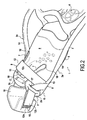
- the palm 1 comprises a footwear portion 2 open at the rear, said footwear portion 2 being delimited at its lateral sides 2b, 2c, as illustrated in FIG. figure 2 .
- the strap 12 has a length greater than that illustrated in FIG. figure 1 so as to extend the end portions 12a, 12b on the back of the foot and preferably to allow attachment of said end portions 12a, 12b in the rear area of the foot, as illustrated in FIG. figure 2 .
- a portion 12c of the strap covers the top of the footwear portion extending from the lateral sides of the bearing portion 3, at the openings 13, while the end portions 12a, 12b of said strap cover the rear of the foot, which ensures both a tightening of the footwear portion around the foot and a nested position of the foot inside said foot portion 2.
- openings 17 are preferably of the passing type; it can however provide the implementation of slot. Moreover, as illustrated in figure 3 , there can be provided an opening 17 of type consisting of two portions 17a, 17b between which is formed a narrow passage 17c facilitating the positioning of the end portions 12a, 12b in said passer on the footwear part 2.
- padding 18 is provided on the strap, in the region of the end portions 12a, 12b which can be fixed together.
- this padding 18 is secured to one of the ends and in particular the end 12b on which are arranged the loops of the fastening means. It can also provide that padding 18 is removable.
- At least one of the lateral sides 2b, 2c comprises an extension 20 positioned behind the foot during the introduction of the strap 12.
- this palm 2 The operation and use of this palm 2 are relatively easy for the user since, to insert his foot in the palm, it suffices to loosen the strap 12 and advance the tongue 10 forward so as to spare the largest free space for the insertion of the foot.
- FIGS. figures 1 and 2 In order to facilitate the movement of the tongue 10, it is provided as shown in FIGS. figures 1 and 2 an enlargement 16 at the ends of the slots 7.
- the user drops the tongue 10 and ensures the tightening around his foot by pulling on the strap 12 and then fixing it at the hook-type fastening means, or on the top of the footwear part 2 in the case illustrated in figure 1 , either on the back of the user's foot in the case illustrated in figure 2 .
- clamping means 9 makes it possible to adjust or readjust the palm even when the user is in the water.
- the end portions 12a, 12b of the strap 12, on which the fastening means 15 are positioned be removable.
Landscapes
- Health & Medical Sciences (AREA)
- General Health & Medical Sciences (AREA)
- Physical Education & Sports Medicine (AREA)
- Footwear And Its Accessory, Manufacturing Method And Apparatuses (AREA)
- Acyclic And Carbocyclic Compounds In Medicinal Compositions (AREA)
- Building Environments (AREA)
Claims (20)
- Flosse (1), umfassend einen flexiblen Schuhteil (2), einen starren Stützteil (3), wobei der Stützteil ein Blatt (4) und einen Bereich zur Aufnahme (5) des Schuhteils enthält, sowie Verbindungsmittel (6) zwischen dem Schuhteil (2) und dem Stützteil (3), wobei der Schuhteil (2) an seiner Oberseite (8) wenigstens einen Schlitz (7) aufweist, der sich teilweise über die Länge des Schuhteils erstreckt, dadurch gekennzeichnet, daß Feststellmittel (9) zwischen dem Schuhteil und dem Stützteil angeordnet sind, um sich an den Seitenkanten (3a, 3b) des Stützteils (3) direkt oder indirekt wenigstens abzustützen und beim Feststellen einen Druck auf die Oberseite (8) des Schuhteils auszuüben, um das Zusammenziehen des Schlitzes des Schuhteils sicherzustellen.
- Flosse (1) nach Anspruch 1, wobei die Feststellmittel (9) einen Riemen (12) umfassen, der an den Seitenkanten (3a, 3b) des Stützteils (3) befestigt ist und von dem wenigstens ein Abschnitt (12c) oberhalb der Oberseite (8) des Schuhteils (2) angeordnet ist, wobei der Riemen eine Öffnung (13) durchgreift, die an einem starren Teil (19, 14) ausgebildet ist, das an wenigstens einer der Seitenkanten der Flosse angeordnet ist, wobei das Teil direkt oder indirekt an dem Stützteil (3) und an dem Schuhteil befestigt ist, wobei Befestigungsmittel (15) an dem Riemen angeordnet sind, um wenigstens den Abschnitt (12c) an die Oberfläche der Oberseite (8) gedrückt zu halten.
- Flosse (1) nach Anspruch 2, wobei ein mit einer Öffnung (13) versehenes starres Teil (19, 14) an jeder Seitenkante (3a, 3b) der Flosse angeordnet ist, wobei der Riemen (12) die Öffnungen an den Seitenkanten durchgreift.
- Flosse (1) nach einem der Ansprüche 2 oder 3, wobei der Stützteil (3) zwei Seitenarme (14) umfaßt, wobei der Riemen (12) an den Seitenarmen befestigt ist, wobei eine Öffnung (13) im Bereich von wenigstens einem der Seitenarme (14) des Stützteils angeordnet ist.
- Flosse (1) nach einem der Ansprüche 2 oder 3, wobei der Stützteil (3) zwei starre seitliche Erweiterungen (19) aufweist, wobei der Riemen (12) an den Erweiterungen (19) befestigt ist, wobei eine Öffnung (13) im Bereich von wenigstens einer der Erweiterungen (19) ausgebildet ist.
- Flosse (1) nach einem der Ansprüche 2 bis 5, wobei die Befestigungsmittel (15) vom Einsteck- und Aufnahmetyp sind, die jeweils in den beiden Endteilen (12a, 12b) des Riemens (12) angeordnet sind.
- Flosse (1) nach Anspruch 6, wobei die Befestigungsmittel (15) vom Typ Klettverschluß sind.
- Flosse (1) nach Anspruch 6, wobei die Befestigungsmittel vom Typ Steck-Rastsystem sind.
- Flosse (1) nach einem der Ansprüche 6 bis 8, wobei die Befestigungsmittel (15) lösbar sind.
- Flosse (1) nach einem der Ansprüche 6 bis 9, wobei der Schuhteil (2) an der Rückseite (2a) geschlossen ist, wobei die Länge des Riemens (12) derart bemessen ist, daß die beiden Endteile (12a, 12b) des Riemens an der Oberfläche der Oberseite (8) des Schuhteils untereinander befestigt sind und daß der Riemen einen Druck auf die Oberseite ausübt.
- Flosse (1) nach einem der Ansprüche 6 bis 9, wobei der Schuhteil (2) an der Rückseite offen ist, wobei die Länge des Riemens (12) derart bemessen ist, daß die beiden Endteile (12a, 12b) hinten am Fuß untereinander befestigt sind und daß der Riemen einen Druck auf die Oberseite des Schuhteils sowie einen Druck auf die Rückseite des Fußes für den Halt des in den Schuhteil eingesteckten Fußes sicherstellt.
- Flosse (1) nach Anspruch 11, wobei der Schuhteil an jeder seiner Seitenwände (2b, 2c) wenigstens eine Öffnung (17) umfaßt, die den Durchgang der Endteile (12a, 12b) des Riemens (12) sowie das Festziehen des Riemens an den Seitenwänden (2b, 2c) des Schuhteils sicherstellt.
- Flosse (1) nach einem der Ansprüche 11 oder 12, wobei der Riemen (12) eine Polsterung (18) umfaßt.
- Flosse (1) nach Anspruch 12, wobei wenigstens eine der Seitenwände (2b, 2c) des Schuhteils (2) eine Verlängerung (20) aufweist.
- Flosse (1) nach Anspruch 12, wobei die Öffnung (17) schlaufenartig und von zwei Teilen (17a, 17b) gebildet ist, zwischen denen ein Durchgang (17c) für die Positionierung der Endteile (12a, 12b) des Riemens (12) ausgebildet ist.
- Flosse (1) nach einem der Ansprüche 2 bis 15, wobei die Feststellmittel (9) wenigstens eine Schlaufe (11) umfassen, die an dem Schuhteil (2) angeordnet ist und das Festziehen des Schuhteils sicherstellt, wobei der Riemen (12) die wenigstens eine Schlaufe durchgreift.
- Flosse (1) nach Anspruch 16, wobei wenigstens eine Schlaufe (11) im Bereich der Oberseite des Schuhteils angeordnet ist.
- Flosse (1) nach einem der Ansprüche 1 bis 17, wobei der Schuhteil (2) zwei Schlitze (7) umfaßt, welche die Bildung einer Zunge (10) ermöglichen.
- Flosse (1) nach Anspruch 18, wobei die Zunge (10) und der Schuhteil (2) einstückig ausgebildet sind.
- Schwimmflosse nach einem der Ansprüche 1 bis 19, wobei der wenigstens eine Schlitz (7) eine Erweiterung (16) im Bereich seines geschlossenen Endes aufweist.
Applications Claiming Priority (2)
| Application Number | Priority Date | Filing Date | Title |
|---|---|---|---|
| FR0850589A FR2926999B1 (fr) | 2008-01-31 | 2008-01-31 | Palme de natation |
| FR0950168A FR2940917B1 (fr) | 2009-01-14 | 2009-01-14 | Palme |
Publications (2)
| Publication Number | Publication Date |
|---|---|
| EP2085122A1 EP2085122A1 (de) | 2009-08-05 |
| EP2085122B1 true EP2085122B1 (de) | 2011-03-23 |
Family
ID=40670950
Family Applications (1)
| Application Number | Title | Priority Date | Filing Date |
|---|---|---|---|
| EP09150750A Not-in-force EP2085122B1 (de) | 2008-01-31 | 2009-01-16 | Schwimmflosse |
Country Status (3)
| Country | Link |
|---|---|
| EP (1) | EP2085122B1 (de) |
| AT (1) | ATE502684T1 (de) |
| DE (1) | DE602009000923D1 (de) |
Families Citing this family (1)
| Publication number | Priority date | Publication date | Assignee | Title |
|---|---|---|---|---|
| CN104338292A (zh) * | 2014-11-18 | 2015-02-11 | 曹伟 | 水下仿生助游袜鞋 |
Family Cites Families (4)
| Publication number | Priority date | Publication date | Assignee | Title |
|---|---|---|---|---|
| FR1190346A (fr) | 1958-01-22 | 1959-10-12 | Chaussure de natation | |
| US5266062A (en) * | 1992-07-28 | 1993-11-30 | John L. Runckel Trust | Amphibious footwear |
| IT1285634B1 (it) | 1996-03-22 | 1998-06-18 | Pio Maria Guglielmo Curatolo | Calzatura anfibia |
| US6663452B1 (en) | 2002-10-22 | 2003-12-16 | Robert J. Myers | Aquatic fins |
-
2009
- 2009-01-16 DE DE602009000923T patent/DE602009000923D1/de active Active
- 2009-01-16 AT AT09150750T patent/ATE502684T1/de not_active IP Right Cessation
- 2009-01-16 EP EP09150750A patent/EP2085122B1/de not_active Not-in-force
Also Published As
| Publication number | Publication date |
|---|---|
| EP2085122A1 (de) | 2009-08-05 |
| DE602009000923D1 (de) | 2011-05-05 |
| ATE502684T1 (de) | 2011-04-15 |
Similar Documents
| Publication | Publication Date | Title |
|---|---|---|
| EP1112697B1 (de) | Schuh mit hohem Schaft und Schnürverschluss | |
| EP0826318B2 (de) | Sportschuh mit nachgiebigen und zugfesten Umlenkungsvorrichtungen | |
| FR2914542A1 (fr) | Chaussure notamment de sport ou de loisirs | |
| FR2872389A1 (fr) | Article chaussant et systeme de lacage pour un tel article | |
| EP2613654B1 (de) | Sandale und entsprechendes herstellungsverfahren | |
| EP0916273B1 (de) | Schischuh | |
| FR2827486A1 (fr) | Chaussure de sport comportant un systeme de serrage perfectionne | |
| EP1712147B1 (de) | Leicht anzuziehender Sportschuh | |
| EP2100644B1 (de) | Schwimmflosse regulierbar nach der Größe des Fuss | |
| FR2953731A1 (fr) | Palme a voilure pivotante equipee d'un systeme de butee | |
| FR2736514A1 (fr) | Botte de surf de neige comprenant une coque interne et une partie dorsale rigide articulee | |
| FR2926999A1 (fr) | Palme de natation | |
| EP2085122A1 (de) | Schwimmflosse | |
| EP1327467A1 (de) | Vorrichtung zum Befestigen eines Schuhs auf einem Sportgerät | |
| EP3491955B1 (de) | Spannvorrichtung für sportschuh | |
| FR2940917A1 (fr) | Palme | |
| EP2213342B1 (de) | Gurthaltevorrichtung für einen Schuh auf einem Sportgerät | |
| EP2324889B1 (de) | Schwimmflosse, die über ein asymmetrisch biegbares Flossenblatt verfügt | |
| EP1555050A2 (de) | Verbesserung einer Haltegurtbefestigung oder dergleichen für einen Schuh an einem Sportgerät | |
| EP0359703B1 (de) | Skischuh | |
| EP2382886B1 (de) | Schuh zum Alpinskifahren | |
| EP1530987A1 (de) | Snowboardbindung | |
| FR2819196A3 (fr) | Element de serrage, en particulier pour des fixations pour des chaussures de sport | |
| WO2004077978A1 (fr) | Chaussure a serrage rapide, patin a glace comportant une telle chaussure, et dispositif de serrage rapide pour cette chaussure | |
| EP2431082B1 (de) | Schneeschuhbindung |
Legal Events
| Date | Code | Title | Description |
|---|---|---|---|
| PUAI | Public reference made under article 153(3) epc to a published international application that has entered the european phase |
Free format text: ORIGINAL CODE: 0009012 |
|
| AK | Designated contracting states |
Kind code of ref document: A1 Designated state(s): AT BE BG CH CY CZ DE DK EE ES FI FR GB GR HR HU IE IS IT LI LT LU LV MC MK MT NL NO PL PT RO SE SI SK TR |
|
| AX | Request for extension of the european patent |
Extension state: AL BA RS |
|
| RIN1 | Information on inventor provided before grant (corrected) |
Inventor name: GUILLOT, FREDERIC Inventor name: SEYNHAVE, JEAN MARC |
|
| 17P | Request for examination filed |
Effective date: 20090911 |
|
| 17Q | First examination report despatched |
Effective date: 20090928 |
|
| AKX | Designation fees paid |
Designated state(s): AT BE BG CH CY CZ DE DK EE ES FI FR GB GR HR HU IE IS IT LI LT LU LV MC MK MT NL NO PL PT RO SE SI SK TR |
|
| GRAP | Despatch of communication of intention to grant a patent |
Free format text: ORIGINAL CODE: EPIDOSNIGR1 |
|
| RIC1 | Information provided on ipc code assigned before grant |
Ipc: A63B 31/11 20060101AFI20101111BHEP |
|
| GRAS | Grant fee paid |
Free format text: ORIGINAL CODE: EPIDOSNIGR3 |
|
| GRAA | (expected) grant |
Free format text: ORIGINAL CODE: 0009210 |
|
| AK | Designated contracting states |
Kind code of ref document: B1 Designated state(s): AT BE BG CH CY CZ DE DK EE ES FI FR GB GR HR HU IE IS IT LI LT LU LV MC MK MT NL NO PL PT RO SE SI SK TR |
|
| REG | Reference to a national code |
Ref country code: GB Ref legal event code: FG4D Free format text: NOT ENGLISH |
|
| REG | Reference to a national code |
Ref country code: CH Ref legal event code: EP |
|
| REG | Reference to a national code |
Ref country code: IE Ref legal event code: FG4D |
|
| REF | Corresponds to: |
Ref document number: 602009000923 Country of ref document: DE Date of ref document: 20110505 Kind code of ref document: P |
|
| REG | Reference to a national code |
Ref country code: DE Ref legal event code: R096 Ref document number: 602009000923 Country of ref document: DE Effective date: 20110505 |
|
| REG | Reference to a national code |
Ref country code: ES Ref legal event code: FG2A Ref document number: 2362830 Country of ref document: ES Kind code of ref document: T3 Effective date: 20110713 |
|
| REG | Reference to a national code |
Ref country code: NL Ref legal event code: VDEP Effective date: 20110323 |
|
| PG25 | Lapsed in a contracting state [announced via postgrant information from national office to epo] |
Ref country code: GR Free format text: LAPSE BECAUSE OF FAILURE TO SUBMIT A TRANSLATION OF THE DESCRIPTION OR TO PAY THE FEE WITHIN THE PRESCRIBED TIME-LIMIT Effective date: 20110624 Ref country code: LV Free format text: LAPSE BECAUSE OF FAILURE TO SUBMIT A TRANSLATION OF THE DESCRIPTION OR TO PAY THE FEE WITHIN THE PRESCRIBED TIME-LIMIT Effective date: 20110323 Ref country code: SE Free format text: LAPSE BECAUSE OF FAILURE TO SUBMIT A TRANSLATION OF THE DESCRIPTION OR TO PAY THE FEE WITHIN THE PRESCRIBED TIME-LIMIT Effective date: 20110323 Ref country code: LT Free format text: LAPSE BECAUSE OF FAILURE TO SUBMIT A TRANSLATION OF THE DESCRIPTION OR TO PAY THE FEE WITHIN THE PRESCRIBED TIME-LIMIT Effective date: 20110323 Ref country code: HR Free format text: LAPSE BECAUSE OF FAILURE TO SUBMIT A TRANSLATION OF THE DESCRIPTION OR TO PAY THE FEE WITHIN THE PRESCRIBED TIME-LIMIT Effective date: 20110323 |
|
| LTIE | Lt: invalidation of european patent or patent extension |
Effective date: 20110323 |
|
| PG25 | Lapsed in a contracting state [announced via postgrant information from national office to epo] |
Ref country code: AT Free format text: LAPSE BECAUSE OF FAILURE TO SUBMIT A TRANSLATION OF THE DESCRIPTION OR TO PAY THE FEE WITHIN THE PRESCRIBED TIME-LIMIT Effective date: 20110323 Ref country code: SI Free format text: LAPSE BECAUSE OF FAILURE TO SUBMIT A TRANSLATION OF THE DESCRIPTION OR TO PAY THE FEE WITHIN THE PRESCRIBED TIME-LIMIT Effective date: 20110323 Ref country code: FI Free format text: LAPSE BECAUSE OF FAILURE TO SUBMIT A TRANSLATION OF THE DESCRIPTION OR TO PAY THE FEE WITHIN THE PRESCRIBED TIME-LIMIT Effective date: 20110323 Ref country code: CY Free format text: LAPSE BECAUSE OF FAILURE TO SUBMIT A TRANSLATION OF THE DESCRIPTION OR TO PAY THE FEE WITHIN THE PRESCRIBED TIME-LIMIT Effective date: 20110323 Ref country code: BG Free format text: LAPSE BECAUSE OF FAILURE TO SUBMIT A TRANSLATION OF THE DESCRIPTION OR TO PAY THE FEE WITHIN THE PRESCRIBED TIME-LIMIT Effective date: 20110623 Ref country code: NO Free format text: LAPSE BECAUSE OF FAILURE TO SUBMIT A TRANSLATION OF THE DESCRIPTION OR TO PAY THE FEE WITHIN THE PRESCRIBED TIME-LIMIT Effective date: 20110623 |
|
| REG | Reference to a national code |
Ref country code: IE Ref legal event code: FD4D |
|
| PG25 | Lapsed in a contracting state [announced via postgrant information from national office to epo] |
Ref country code: EE Free format text: LAPSE BECAUSE OF FAILURE TO SUBMIT A TRANSLATION OF THE DESCRIPTION OR TO PAY THE FEE WITHIN THE PRESCRIBED TIME-LIMIT Effective date: 20110323 Ref country code: PT Free format text: LAPSE BECAUSE OF FAILURE TO SUBMIT A TRANSLATION OF THE DESCRIPTION OR TO PAY THE FEE WITHIN THE PRESCRIBED TIME-LIMIT Effective date: 20110725 |
|
| PG25 | Lapsed in a contracting state [announced via postgrant information from national office to epo] |
Ref country code: RO Free format text: LAPSE BECAUSE OF FAILURE TO SUBMIT A TRANSLATION OF THE DESCRIPTION OR TO PAY THE FEE WITHIN THE PRESCRIBED TIME-LIMIT Effective date: 20110323 Ref country code: IS Free format text: LAPSE BECAUSE OF FAILURE TO SUBMIT A TRANSLATION OF THE DESCRIPTION OR TO PAY THE FEE WITHIN THE PRESCRIBED TIME-LIMIT Effective date: 20110723 Ref country code: SK Free format text: LAPSE BECAUSE OF FAILURE TO SUBMIT A TRANSLATION OF THE DESCRIPTION OR TO PAY THE FEE WITHIN THE PRESCRIBED TIME-LIMIT Effective date: 20110323 Ref country code: CZ Free format text: LAPSE BECAUSE OF FAILURE TO SUBMIT A TRANSLATION OF THE DESCRIPTION OR TO PAY THE FEE WITHIN THE PRESCRIBED TIME-LIMIT Effective date: 20110323 |
|
| PG25 | Lapsed in a contracting state [announced via postgrant information from national office to epo] |
Ref country code: NL Free format text: LAPSE BECAUSE OF FAILURE TO SUBMIT A TRANSLATION OF THE DESCRIPTION OR TO PAY THE FEE WITHIN THE PRESCRIBED TIME-LIMIT Effective date: 20110323 |
|
| PLBE | No opposition filed within time limit |
Free format text: ORIGINAL CODE: 0009261 |
|
| STAA | Information on the status of an ep patent application or granted ep patent |
Free format text: STATUS: NO OPPOSITION FILED WITHIN TIME LIMIT |
|
| PG25 | Lapsed in a contracting state [announced via postgrant information from national office to epo] |
Ref country code: IE Free format text: LAPSE BECAUSE OF FAILURE TO SUBMIT A TRANSLATION OF THE DESCRIPTION OR TO PAY THE FEE WITHIN THE PRESCRIBED TIME-LIMIT Effective date: 20110323 |
|
| 26N | No opposition filed |
Effective date: 20111227 |
|
| PG25 | Lapsed in a contracting state [announced via postgrant information from national office to epo] |
Ref country code: PL Free format text: LAPSE BECAUSE OF FAILURE TO SUBMIT A TRANSLATION OF THE DESCRIPTION OR TO PAY THE FEE WITHIN THE PRESCRIBED TIME-LIMIT Effective date: 20110323 Ref country code: DK Free format text: LAPSE BECAUSE OF FAILURE TO SUBMIT A TRANSLATION OF THE DESCRIPTION OR TO PAY THE FEE WITHIN THE PRESCRIBED TIME-LIMIT Effective date: 20110323 |
|
| REG | Reference to a national code |
Ref country code: DE Ref legal event code: R097 Ref document number: 602009000923 Country of ref document: DE Effective date: 20111227 |
|
| BERE | Be: lapsed |
Owner name: DECATHLON Effective date: 20120131 |
|
| PG25 | Lapsed in a contracting state [announced via postgrant information from national office to epo] |
Ref country code: MC Free format text: LAPSE BECAUSE OF NON-PAYMENT OF DUE FEES Effective date: 20120131 |
|
| PG25 | Lapsed in a contracting state [announced via postgrant information from national office to epo] |
Ref country code: BE Free format text: LAPSE BECAUSE OF NON-PAYMENT OF DUE FEES Effective date: 20120131 |
|
| PG25 | Lapsed in a contracting state [announced via postgrant information from national office to epo] |
Ref country code: MK Free format text: LAPSE BECAUSE OF FAILURE TO SUBMIT A TRANSLATION OF THE DESCRIPTION OR TO PAY THE FEE WITHIN THE PRESCRIBED TIME-LIMIT Effective date: 20110323 |
|
| PG25 | Lapsed in a contracting state [announced via postgrant information from national office to epo] |
Ref country code: MT Free format text: LAPSE BECAUSE OF FAILURE TO SUBMIT A TRANSLATION OF THE DESCRIPTION OR TO PAY THE FEE WITHIN THE PRESCRIBED TIME-LIMIT Effective date: 20110323 |
|
| REG | Reference to a national code |
Ref country code: CH Ref legal event code: PL |
|
| PG25 | Lapsed in a contracting state [announced via postgrant information from national office to epo] |
Ref country code: LI Free format text: LAPSE BECAUSE OF NON-PAYMENT OF DUE FEES Effective date: 20130131 Ref country code: CH Free format text: LAPSE BECAUSE OF NON-PAYMENT OF DUE FEES Effective date: 20130131 |
|
| PG25 | Lapsed in a contracting state [announced via postgrant information from national office to epo] |
Ref country code: TR Free format text: LAPSE BECAUSE OF FAILURE TO SUBMIT A TRANSLATION OF THE DESCRIPTION OR TO PAY THE FEE WITHIN THE PRESCRIBED TIME-LIMIT Effective date: 20110323 |
|
| PG25 | Lapsed in a contracting state [announced via postgrant information from national office to epo] |
Ref country code: LU Free format text: LAPSE BECAUSE OF NON-PAYMENT OF DUE FEES Effective date: 20120116 |
|
| PG25 | Lapsed in a contracting state [announced via postgrant information from national office to epo] |
Ref country code: HU Free format text: LAPSE BECAUSE OF FAILURE TO SUBMIT A TRANSLATION OF THE DESCRIPTION OR TO PAY THE FEE WITHIN THE PRESCRIBED TIME-LIMIT Effective date: 20090116 |
|
| REG | Reference to a national code |
Ref country code: FR Ref legal event code: PLFP Year of fee payment: 8 |
|
| REG | Reference to a national code |
Ref country code: FR Ref legal event code: PLFP Year of fee payment: 9 |
|
| REG | Reference to a national code |
Ref country code: FR Ref legal event code: PLFP Year of fee payment: 10 |
|
| REG | Reference to a national code |
Ref country code: DE Ref legal event code: R082 Ref document number: 602009000923 Country of ref document: DE Representative=s name: CBDL PATENTANWAELTE GBR, DE Ref country code: DE Ref legal event code: R082 Ref document number: 602009000923 Country of ref document: DE Representative=s name: CBDL PATENTANWAELTE EGBR, DE |
|
| P01 | Opt-out of the competence of the unified patent court (upc) registered |
Effective date: 20230605 |
|
| PGFP | Annual fee paid to national office [announced via postgrant information from national office to epo] |
Ref country code: ES Payment date: 20240207 Year of fee payment: 16 |
|
| PGFP | Annual fee paid to national office [announced via postgrant information from national office to epo] |
Ref country code: DE Payment date: 20240115 Year of fee payment: 16 Ref country code: GB Payment date: 20240119 Year of fee payment: 16 |
|
| PGFP | Annual fee paid to national office [announced via postgrant information from national office to epo] |
Ref country code: IT Payment date: 20240110 Year of fee payment: 16 Ref country code: FR Payment date: 20240123 Year of fee payment: 16 |
|
| REG | Reference to a national code |
Ref country code: DE Ref legal event code: R119 Ref document number: 602009000923 Country of ref document: DE |
|
| GBPC | Gb: european patent ceased through non-payment of renewal fee |
Effective date: 20250116 |
|
| PG25 | Lapsed in a contracting state [announced via postgrant information from national office to epo] |
Ref country code: DE Free format text: LAPSE BECAUSE OF NON-PAYMENT OF DUE FEES Effective date: 20250801 |
|
| PG25 | Lapsed in a contracting state [announced via postgrant information from national office to epo] |
Ref country code: GB Free format text: LAPSE BECAUSE OF NON-PAYMENT OF DUE FEES Effective date: 20250116 |
|
| PG25 | Lapsed in a contracting state [announced via postgrant information from national office to epo] |
Ref country code: FR Free format text: LAPSE BECAUSE OF NON-PAYMENT OF DUE FEES Effective date: 20250131 |
|
| PG25 | Lapsed in a contracting state [announced via postgrant information from national office to epo] |
Ref country code: IT Free format text: LAPSE BECAUSE OF NON-PAYMENT OF DUE FEES Effective date: 20250116 |
|
| REG | Reference to a national code |
Ref country code: ES Ref legal event code: FD2A Effective date: 20260227 |
|
| PG25 | Lapsed in a contracting state [announced via postgrant information from national office to epo] |
Ref country code: ES Free format text: LAPSE BECAUSE OF NON-PAYMENT OF DUE FEES Effective date: 20250117 |