EP2085183B1 - Outil de serrage et/ou d'écartement doté d'une tige de poussée ou de traction - Google Patents
Outil de serrage et/ou d'écartement doté d'une tige de poussée ou de traction Download PDFInfo
- Publication number
- EP2085183B1 EP2085183B1 EP09002670A EP09002670A EP2085183B1 EP 2085183 B1 EP2085183 B1 EP 2085183B1 EP 09002670 A EP09002670 A EP 09002670A EP 09002670 A EP09002670 A EP 09002670A EP 2085183 B1 EP2085183 B1 EP 2085183B1
- Authority
- EP
- European Patent Office
- Prior art keywords
- push
- pull rod
- clamping
- lock
- lever
- Prior art date
- Legal status (The legal status is an assumption and is not a legal conclusion. Google has not performed a legal analysis and makes no representation as to the accuracy of the status listed.)
- Expired - Lifetime
Links
Images




Classifications
-
- B—PERFORMING OPERATIONS; TRANSPORTING
- B25—HAND TOOLS; PORTABLE POWER-DRIVEN TOOLS; MANIPULATORS
- B25B—TOOLS OR BENCH DEVICES NOT OTHERWISE PROVIDED FOR, FOR FASTENING, CONNECTING, DISENGAGING, OR HOLDING
- B25B5/00—Clamps
- B25B5/06—Arrangements for positively actuating jaws
- B25B5/068—Arrangements for positively actuating jaws with at least one jaw sliding along a bar
Definitions
- the invention relates to a clamping and / or spreading tool with a push or pull rod.
- the push or pull rod is held displaceable on a support of the clamping and / or spreading tool.
- the clamping and / or spreading tool has a stationary jaw, which is fixedly connected to the carrier, and a fixed to the push or pull rod movable jaw, which can be moved by displacement of the push or pull rod relative to the fixed jaw.
- a step mechanism which has an actuating lever which is pivotally mounted on the carrier, and a tiltable by the actuating lever on the push or pull rod driver.
- the indexer is designed to convert the stroke of the actuating lever into a feed of the push or pull rod.
- the push or pull rod For clamping a workpiece, the push or pull rod is displaced over the tilted driver towards the fixed jaw and for generating spreading forces away from the fixed jaw. A lock prevents sliding back of the push or pull rod.
- a clamping and / or spreading tool which has a displaceable, lying on the actuating side pivot point of the actuating lever for generating higher clamping forces.
- a reverse lock consists of a plate-like, always tilted in the unactuated state due to a tension spring locking plate. The release of clamping forces on the lock plate is realized by a separate release lever. Even with such clamping and / or spreading tools, the clamping forces are released explosively at unlocking the unlocking, and it is a relatively high expenditure of force necessary for this.
- a clamping or spreading tool which leverages the leverage of a long operating lever to a mounted near the pivot point of the lever rod to achieve high clamping forces and a large feed, is from the WO03 / 0137193 A known.
- This clamping tool can be absorbed by the lock only low holding forces.
- At least one lock is provided in the clamping and / or spreading tool according to the invention, the displacement against a clamping and / or spreading direction characterized locks that it is tilted by at least one coercive means, such as a spring, in particular coil spring, against the pull or push rod.
- at least one coercive means such as a spring, in particular coil spring
- At least one plate of the barrier for forming the desired tilting relative to the push or pull rod is pivoted by a positive means about a support of the clamping and / or spreading stationary support point displaceably mounted on a push or pull rod.
- the fixed contact point can be positioned on the tension side of the push or pull rod.
- the stationary abutment point about which the at least one plate of the lock is pivoted to form the tilting, and another abutment point about which at least one drive plate of the transmission mechanism due to a coercive means, such as a compression spring, pivoted to form a jamming with the push or pull rod are arranged at substantially the same level with respect to the push or pull rod.
- the coercive means and the unblocking device are adapted to each other in such a way that they functionally engage with the lock on opposite sides of the push or pull rod, namely the positive means for tilting the lock and the unlocking device Solution of the blocking effect of the tilted barrier.
- the measure according to the invention a large, user-friendly operating lever for releasing the lock can be made available to operators. Firstly, it is achieved according to the invention that the unlocking device comes into engagement with the barrier remote from the force entry point of the coercive means, and secondly that the point of engagement of the unlocking device is realized away from the tilting of the barrier and the push or pull rod.
- the coercive means may be on the actuation side of the push or pull rod and the unlocking device can engage on the tension side of the push or pull rod with the lock.
- a particularly simple structural measure for tilting the lock against the pull rod can be realized that the lock by the coercive means a fixed point is pivoted, which lies on that side of the push and / or pull rod, which is opposite to the side at which the engagement point of the unblocking device is located.
- the wedging effect of the lock causing means on the tension side of the push or pull rod and the tilt canceling unlocking come on the operating side of the push or pull rod with the lock in engagement.
- two coercive means such as two compression springs, are provided for one of the at least one barrier.
- Such Zwangsmittelschreib that holds the lock in a tilted position relative to the push or pull rod and reliably prevents a shift back of the push or pull rod, also causes when operating the indexer of the clamping and / or spreading tool, ie at a displacement of Push or pull rod in the clamping and / or spreading direction, an unwanted Mitlegagerung the lock is prevented.
- a first coercive means are arranged on the actuation side of the push or pull rod and a second coercive means on the tension side of the push or pull rod.
- the coercive means in particular a fixed pivot point of the lock whereliegt, provides a secure tilting of the lock, while the remote to the fixed pivot coercive means mainly Mitlegagerung the lock on actuation of the indexer of the clamping and / or spreading tool in derogation.
- a preferred embodiment of the invention is that in the clamping tool according to the invention, the displacement of the push or pull rod against a clamping and / or spreading direction is locked by a gear mechanism for displacing in the clamping and / or spreading direction and by an independent from the gear mechanism lock.
- An unlocking device is designed to lift the blocking effect of the transmission mechanism and the lock when actuated.
- the unlocking device can be designed to cancel the blocking effect of the gear mechanism and the lock substantially simultaneously when actuated.
- the unblocking device is designed to cancel the blocking effect of the transmission mechanism and the lock successively, in particular the blocking effect of the transmission mechanism before the blocking effect of the lock.
- the unlocking device may be adapted to act on the gear mechanism and the lock in a predetermined stepwise unlocking sequence.
- the blocking effect of the transmission mechanism can be caused by a driver for displacing the clamping and / or spreading direction is always tilted by a force means, ie even in the unactuated state of the actuating lever, wherein the coercive means and the driver are coordinated such that after a Actuating and during the slipping back of an operating lever of the transmission mechanism is no tilting of the driver relative to the push or pull rod.
- tilting the driver is achieved that no Betrelifactshubux the actuating arm must be accepted.
- the tilting of the driver prevents that the push or pull rod displaced in the rest state of the transmission mechanism against the feed direction.
- the lock can be made in several parts, namely the fact that a locking plate is brought by a positive means in a always tilted position relative to the push or pull rod, so that a displacement against the feed direction of the thrust or pull rod is prevented and the clamping forces generated between the jaws are stored.
- the coercive means is a spring, preferably a coil spring, which may be designed as a compression spring or as a tension spring and on the one hand acts on the blocking plate and on the other hand is supported on the carrier or held by the carrier.
- the unlocking device may provide an unlocking lever, which according to the invention can be releasably engaged with the lock.
- a third locking device can be realized that the release lever is spent in the same manner as the driver via a positive means in a relation to the push or pull rod tilted position.
- the unlocking sequence can be defined by first releasing the locking action of the unlocking lever.
- the transmission mechanism for displacing the push or pull rod in the clamping or spreading direction can be designed to generate high clamping forces.
- the transmission mechanism may comprise an actuating arm which is pivotally mounted on a clamping side of the push or pull rod and also on the tension side with the driver force-transmission in engagement.
- the barrier may be designed to be supported on a fixed side of the clamping and / or spreading tool, in particular a stop of the carrier displaceably mounted on the push or pull rod, on a tension side of the push or pull rod.
- the unlocking device may comprise a release lever or locking lever, with which a component for transmitting the actuating movement of the release lever is coupled, which component acts releasably upon actuation of the release lever on the transmission mechanism and the lock.
- the release lever can act on the lock directly reversing the canting, while the canting of the transmission mechanism is canceled via the component for transmitting the actuating movement.
- the component part may be designed as a spring-biased rod, which is mounted in particular displaceable in the longitudinal direction.
- the release lever may be articulated to a carrier displaceably supporting the push or pull rod, wherein the hinge point of the release lever is arranged substantially at the level of the push or pull rod.
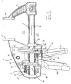
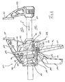
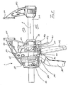
- FIGS. 1 to 3 show a clamping tool 1 with a support 3 to which a stationary jaw 5 is firmly connected and a push or pull rod 7 is held displaceable in the longitudinal direction of the push or pull rod 7.
- a push or pull rod 7 At one end of the push or Pull rod 7 is releasably attached to an arm 9, at the end of a fixed jaw 5 diametrically opposed movable jaw 11 is fixed, with the movable jaw 11 moves to the stationary jaw 5 by displacement of the push or pull rod 7. If the arm 9 is arranged to hold the clamping jaw 11 at the other end of the push or pull rod 7, the function of a spreading tool is obtained.
- the carrier 3 forms a housing in which at least partially components of a step transmission are housed.
- An actuating lever 13 extends from an actuating side 15 of the push or pull rod through a housing wall of the carrier 3 through a clamping side 17 of the push or pull rod 7 and is pivotally mounted by a pivot joint 19 on the carrier 3.
- an operator grips the handle 21 with her palm and with her fingers the actuating arm 13 and pulls the actuating lever 13 to the handle to carry out an actuating stroke.
- the actuating lever 13 comprises an active arm 23 which is in constant contact with a gear mechanism 26 in the form of a driver 25, which is formed of three steel plates arranged parallel to one another.
- a recorded in a blind hole 27 compression coil spring 29 forces the driver 25 while exerting a torque about a force input point 31 of the active arm 23 around in a relation to the push or pull rod 7 tilted position, so that a displacement of the push or pull rod 7 against the clamping direction S. is prevented, so a barrier effect is generated.
- the ratio of Betrelinshebelarm w b by the distance of an operating range of the operator on Actuating lever 13 is defined to the pivot joint 19, the Wirkhebelarm w w results and with which short feeds of the push or pull rod 7 in the clamping direction S can be realized at a Betreli Trent and thus very high clamping forces up to 1000 Newton between the jaws 5, 11 are reached when clamping a workpiece, not shown.
- the lever ratio is 10: 1.
- the driver 25 and the plate lock 33 serve to obtain the clamping forces acting on the workpiece.
- the clamping tool 1 has an unlocking device which can be actuated by a lever 3 (40) which is articulated on the carrier 3.
- the unlocking device 41 comprises in addition to the trigger lever 39 is a substantially parallel to the push or pull rod 7 extending plunger 43 which is fixedly mounted on the trigger lever 39 and extends through the plate lock 33 through or past the latter to the canted driver 25.
- a compression spring 45 has the task to spend the release lever 39 in a passive position.
- the unlocking device is designed to solve the locking effects of the blocking components (25, 33) successively upon actuation of the trigger lever 39, wherein preferably here first the blocking effect of the tilted driver 25 and then the blocking effect of the plate lock 33 is released. This is according to the execution of the FIGS. 1 to 3 achieved in that the distance of the plunger 43 is tuned by the driver on the pivot angle distance between the plate lock 33 and a plate lock 33 near portion of the trigger lever 39.
- the release lever 39 is actuated approximately halfway through its actuation stroke.
- the driver 25 facing the end of the plunger 43 comes into contact with the lying on the actuating side 15 portion of the driver 25 and pivots the driver 25 to the force input point 31 from its tilted position in a substantially to the push or pull rod 7 vertical position, in which would be the push or pull rod through the driver against the clamping direction S displaced.
- the released forces are derived in the housing by elastic deformation of housing parts. In this position, however, a displacement of the push or pull rod against the clamping direction S is not possible because it is hindered by the still existing blocking effect of the locking plates 33, which still maintains at least a portion of the clamping forces between the jaws. Consequently, the operator experiences no explosive release forces when first releasing the locking action of the driver 25.
- Fig. 3 is the trigger lever 39 is fully actuated, so that a portion of the tension-side portion of the trigger lever 39 comes into engagement in the region of the tension-side end of the plate lock 33 and thus the plate lock 33 is pivoted to release the jam and the clamping forces. Due to the distance between the point of engagement of the trigger lever 39 and the compression spring 35 only a small force must be expended to unlock, even if high clamping forces prevail.
- FIGS. 4 to 6 a further embodiment is shown, for better readability of the figure description for identical and similar components for execution according to the FIGS. 1 to 3 the same reference numerals are used, which are increased by 100.
- the clamping tool 101 differs from the clamping tool 1 according to the FIGS. 1 to 3 in that the lock or plate lock 133 is not brought by means of a seated in a receptacle compression spring in the tilted position, but by means of a tension spring, the held at one end by the carrier and engages at the other end in a hole in the plate lock 133.
- Another distinguishing feature is the arrangement of a compression spring 145, which has the task to spend the release lever 139 in a passive position. In the execution according to the FIGS. 4 to 6 the compression spring 145 is not supported on the plate lock 139 but on the carrier 103.
- the plunger 143 does not come into contact with the cam 125 of the gear mechanism 126 at its end, but the plunger 143 is provided with a projecting projection 151 projecting toward the push rod, which can releasably engage the operating side portion of the cam 125 with its canting.
- clamping tool has a step gear, with the even higher clamping forces than with the clamping tool according to the FIGS. 1 to 3 can be caused because the Wirkhebelarm w w with respect to the Betchanistshebelarm w b is even smaller and thus very favorable leverage ratios of 12: 1 to produce high clamping forces.
- FIG. 7 an embodiment of a clamping and / or spreading tool according to the invention is shown, for better readability of the figure description for identical or similar components to the embodiments according to the FIGS. 1 to 6 the same reference numerals are used, which are increased by 100 and 200, respectively.
- the clamping tool 202 differs from the previously described embodiments essentially in that a different lock or plate lock 233 and a different unlocking device 241 are provided.
- the plate lock 233 comprises two plates 232, which are tilted by a schematically indicated positive means in the form of a compression spring 235 relative to the push or pull rod.
- a compression spring 235 By the compression spring 235, the plates 232 of the plate lock 233 are pivoted about a stationary on the carrier 203 of the clamping tool 202 stop 261, which lies on the clamping side 217 of the push or pull rod 207.
- the stop 261 is at the same level with respect to the push rod 207 as the force input point 231 of the operating lever 213 about which the follower 225 is the transmission mechanism 226 be pivoted due to a compression coil spring not shown.
- the unlocking device according to the invention 241 comprises a parallel to the push or pull rod 207 displaceable plunger 243.
- the plunger 243 comprises two protrusions 263, 265, which cooperate entkantend upon actuation of the unblocking device 241 with the plates 232 and the driver 225, the latter against the effect the respective coercive agent are swung back.
- the unlocking device 241 is shown in two operating states, wherein the unactuated operating state is illustrated by solid lines, while the actuated state, ie the release of the blocking effects of the plate lock 233 and the tilted driver 225, is shown by dashed lines.
- the plunger 243 moves in the clamping direction S.
- the projections 263 and 265 respectively to the plates 233 and Drivers arranged that the blocking effect of the plate lock and the transmission mechanism 226 is canceled substantially simultaneously.
- the simultaneous cancellation of the blocking effects is structurally realized in that the distance between the projections 263 and 265 in the clamping direction S to the plates 232 of the plate lock 233 and to the drivers 225 of the transmission mechanism 226 is substantially equal.
- FIG. 8 a further embodiment of a clamping tool according to the invention is shown, wherein for better readability of the figure description for identical and similar components to the embodiments according to the FIGS. 1 to 7 the same reference numerals are used, which are increased by 100, 200 and 300, respectively.
- the clamping tool 301 differs in particular from the clamping tool 201 according to the FIG. 7 in that the disk lock 333 and the unlocking device 341 are made different.
- the plate lock 333 comprises two compression means 371 and 373 designed to cause a pivoting of the plates 332 around the stationary stopper 361 around.
- the compression spring 371 on the clamping side 317 of the push or pull rod 307 causes a secure tilting of the plates 332 relative to the push rod 307, whereby a reliable non-return lock for the push rod 397 is ensured.
- the compression spring 373 on the actuation side 315 of the push or pull rod 307 prevents Mitverlagem the plates 332 of the plate lock 333 as soon as the transmission mechanism 326 is actuated via the actuating lever 313 and the push or pull rod 307 is displaced in the clamping direction S.
- the plates 332 thus always remain in contact with the stop 361.
- the unlocking device 341 includes only a single projection 375, which with the canted drivers 325 of the transmission mechanism 326, the blocking effect in a lifting manner can come as soon as the release lever 339 of the unlocking device 341 is pressed accordingly strong.
- the projection 375 also serves as a stop for a compression spring 345, which pushes the plunger 343 back into its passive starting position, the in FIG. 8 is shown.
- the simultaneity of the Sperr Obersaufhebung is achieved in that the distance of the release lever to the plates 332 and the projection 375 to the drivers 325 is substantially equal.
Landscapes
- Engineering & Computer Science (AREA)
- Mechanical Engineering (AREA)
- Clamps And Clips (AREA)
- Portable Nailing Machines And Staplers (AREA)
- Basic Packing Technique (AREA)
- Jigs For Machine Tools (AREA)
- Conveying And Assembling Of Building Elements In Situ (AREA)
- Packaging Of Annular Or Rod-Shaped Articles, Wearing Apparel, Cassettes, Or The Like (AREA)
- Load-Engaging Elements For Cranes (AREA)
- Screen Printers (AREA)
Claims (5)
- Outil de serrage et/ou d'écartement avec une tige de poussée ou de traction (207, 307), au moins un dispositif de blocage (233, 333) qui bloque un déplacement de la tige de poussée ou de traction (207, 307) vers un sens de serrage et/ou d'écartement (S) par le fait, qu'il est incliné par un moyen de contrainte, comme un ressort, en particulier un ressort de poussée en face de la tige de poussée ou de traction (207, 307) et un dispositif de déblocage (241, 341) qui supprime l'effet de blocage du dispositif de blocage (233, 333) en actionnant un levier de déclenchement (239, 339) articulé sur un support (203,303) de l'outil de serrage et/ou d'écartement (201, 301), pour lequel au moins une plaque (232, 332) du dispositif de blocage (233, 333) est pivotée autour d'un point fixe en face d'un support (203, 303) pour s'incliner par le moyen de contrainte avec la tige de poussée ou de traction (207, 307) montée mobile sur le support (203, 303) et pour lequel le dispositif de déblocage (241, 341) coopère par désinclinaison avec au moins une plaque (232, 332) caractérisé en ce que le point fixe autour duquel est pivotée la plaque du dispositif de blocage (233, 333) et un point de contact autour duquel au moins une plaque d'entraînement d'un mécanisme réducteur (226, 326) est pivotée à son inclinaison avec la tige de poussée ou de traction (207, 307) sont pour l'essentiel disposés à la même hauteur concernant la tige de poussée ou de traction (207,307).
- Outil de serrage et/ou d'écartement selon la revendication 1 caractérisé en ce que le moyen de contrainte et le dispositif de déblocage (241, 341) entrent en prise conformément au fonctionnement au moins avec le dispositif de blocage (233, 333) sur les côtés se faisant face de la tige de poussée ou de traction (207, 307).
- Outil de serrage et/ou d'écartement selon la revendication 1 ou 2 caractérisé en ce que le point fixe autour duquel la plaque (232, 332) du dispositif de blocage (233, 333) est pivotée, est défini sur le côté de serrage (217, 317) de la tige de poussée ou de traction (207, 307) sur le support (203, 303).
- Outil de serrage et/ou d'écartement selon la revendication 1 caractérisé en ce que le moyen de contrainte sur un côté de serrage (317) de la tige de poussée ou de traction (307) et le dispositif de déblocage (341) sur un côté de manoeuvre (315) de la tige de poussée ou de traction (307) se mettent en prise avec le dispositif de blocage.
- Outil de serrage et/ou d'écartement selon une des revendications 1 à 4 caractérisé en ce que deux moyens de contrainte sont prévus pour incliner au moins un dispositif de blocage pour lequel un premier moyen de contrainte est disposé du côté manoeuvre (313) de la tige de poussée ou de traction (307) et un deuxième moyen de contrainte est disposé sur le côté serrage (317) de la tige de poussée ou de traction (307).
Priority Applications (1)
| Application Number | Priority Date | Filing Date | Title |
|---|---|---|---|
| EP11001103.8A EP2324958B1 (fr) | 2004-05-19 | 2004-12-08 | Outil de serrage et/ou d'écartement doté d'une tige de poussée ou de traction |
Applications Claiming Priority (2)
| Application Number | Priority Date | Filing Date | Title |
|---|---|---|---|
| DE102004024862A DE102004024862A1 (de) | 2004-05-19 | 2004-05-19 | Spann- und/oder Spreizwerkzeug |
| EP04803645A EP1750905B1 (fr) | 2004-05-19 | 2004-12-08 | Outil de serrage et/ou d'extension comprenant une tige de poussee ou de traction |
Related Parent Applications (2)
| Application Number | Title | Priority Date | Filing Date |
|---|---|---|---|
| EP04803645A Division EP1750905B1 (fr) | 2004-05-19 | 2004-12-08 | Outil de serrage et/ou d'extension comprenant une tige de poussee ou de traction |
| EP04803645.3 Division | 2004-12-08 |
Related Child Applications (1)
| Application Number | Title | Priority Date | Filing Date |
|---|---|---|---|
| EP11001103.8 Division-Into | 2011-02-10 |
Publications (3)
| Publication Number | Publication Date |
|---|---|
| EP2085183A2 EP2085183A2 (fr) | 2009-08-05 |
| EP2085183A3 EP2085183A3 (fr) | 2009-10-07 |
| EP2085183B1 true EP2085183B1 (fr) | 2013-02-13 |
Family
ID=34959880
Family Applications (3)
| Application Number | Title | Priority Date | Filing Date |
|---|---|---|---|
| EP04803645A Expired - Lifetime EP1750905B1 (fr) | 2004-05-19 | 2004-12-08 | Outil de serrage et/ou d'extension comprenant une tige de poussee ou de traction |
| EP09002670A Expired - Lifetime EP2085183B1 (fr) | 2004-05-19 | 2004-12-08 | Outil de serrage et/ou d'écartement doté d'une tige de poussée ou de traction |
| EP11001103.8A Expired - Lifetime EP2324958B1 (fr) | 2004-05-19 | 2004-12-08 | Outil de serrage et/ou d'écartement doté d'une tige de poussée ou de traction |
Family Applications Before (1)
| Application Number | Title | Priority Date | Filing Date |
|---|---|---|---|
| EP04803645A Expired - Lifetime EP1750905B1 (fr) | 2004-05-19 | 2004-12-08 | Outil de serrage et/ou d'extension comprenant une tige de poussee ou de traction |
Family Applications After (1)
| Application Number | Title | Priority Date | Filing Date |
|---|---|---|---|
| EP11001103.8A Expired - Lifetime EP2324958B1 (fr) | 2004-05-19 | 2004-12-08 | Outil de serrage et/ou d'écartement doté d'une tige de poussée ou de traction |
Country Status (6)
| Country | Link |
|---|---|
| US (2) | US7896322B2 (fr) |
| EP (3) | EP1750905B1 (fr) |
| CN (2) | CN101027162B (fr) |
| AU (2) | AU2004320073B2 (fr) |
| DE (3) | DE102004024862A1 (fr) |
| WO (1) | WO2005115690A1 (fr) |
Families Citing this family (30)
| Publication number | Priority date | Publication date | Assignee | Title |
|---|---|---|---|---|
| DE10297105B4 (de) | 2001-08-10 | 2011-07-21 | American Tool Companies, Inc., Ill. | Mehrfachgeschwindigkeits-Klemmvorrichtungen mit vergrösserter und veränderbarer Kraft |
| EP2359984B1 (fr) * | 2003-08-01 | 2015-07-29 | Irwin Industrial Tool Company | Mécanisme pas à pas pour un outil de serrage et/ou d'écartement et outil de serrage et/ou d'écartement |
| EP1867434B1 (fr) | 2003-12-12 | 2009-09-30 | Irwin Industrial Tools GmbH | Expenseur et/ou détendeur doté d'un mécanisme pas à pas et d'un entraînement par ressort destiné au déplacement continu des deux mâchoires de serrage l'une par rapport à l'autre |
| DE102004024862A1 (de) * | 2004-05-19 | 2006-01-05 | Irwin Industrial Tools Gmbh | Spann- und/oder Spreizwerkzeug |
| US8177203B2 (en) | 2007-04-05 | 2012-05-15 | Stanley Black & Decker, Inc. | Clamp and lever therefor |
| US20090206534A1 (en) * | 2008-02-14 | 2009-08-20 | Mccracken Robert E | CamLock Clamp |
| SE532515C2 (sv) * | 2008-06-02 | 2010-02-16 | Nederman Philip & Co Ab | Anordning för greppning för avgasrör |
| US8430383B2 (en) * | 2008-07-18 | 2013-04-30 | Irwin Industrial Tools Company | Clamp with a support |
| US8443499B2 (en) * | 2009-03-03 | 2013-05-21 | GM Global Technology Operations LLC | Concentric camshaft and method of assembly |
| US9289884B2 (en) * | 2011-01-31 | 2016-03-22 | Sajid Patel | Bar clamp |
| US9091113B2 (en) | 2011-02-21 | 2015-07-28 | Pilgrim Family Enterprises Llc | Safety gate |
| US8438741B2 (en) | 2011-08-05 | 2013-05-14 | Black & Decker, Inc. | Lock for power tool |
| US8882093B2 (en) * | 2012-04-05 | 2014-11-11 | Sheng Pu Promotion Co., Ltd. | Handheld clamping tool |
| US9676079B2 (en) * | 2013-03-11 | 2017-06-13 | Stanley Black & Decker, Inc. | Clamp |
| CN104070480B (zh) | 2013-03-15 | 2018-06-22 | 创科电动工具科技有限公司 | 夹紧和扩张工具 |
| US9211635B2 (en) * | 2013-08-01 | 2015-12-15 | Robert N. Poole | Self-adjusting bar clamp |
| US20150082639A1 (en) * | 2013-09-26 | 2015-03-26 | Greenlee Textron Inc. | Cable stripper |
| US20170136606A1 (en) * | 2014-07-04 | 2017-05-18 | Hangzhou Great Star Tools Co., Ltd. | Clamp |
| USD771456S1 (en) | 2014-08-01 | 2016-11-15 | Milwaukee Electric Tool Corporation | Pliers with control key |
| US20160207175A1 (en) | 2015-01-15 | 2016-07-21 | Milwaukee Electric Tool Corporation | Locking pliers with improved adjustment member |
| USD769110S1 (en) * | 2015-03-10 | 2016-10-18 | Armin Joseph Altemus | Clamp for securing a ladder to fascia |
| USD782891S1 (en) | 2015-04-02 | 2017-04-04 | Milwaukee Electric Tool Corporation | Locking pliers |
| US11077010B2 (en) * | 2017-11-10 | 2021-08-03 | Marc Robert Heller | Soft tissue mobilization device |
| US10843605B2 (en) | 2018-05-10 | 2020-11-24 | Dorel Juvenile Group, Inc. | Headrest-height adjuster for juvenile seat |
| US12384005B2 (en) | 2018-08-29 | 2025-08-12 | New Revo Brand Group, Llc | Ball joint system and support device |
| USD1080371S1 (en) | 2022-12-27 | 2025-06-24 | New Revo Brand Group, Llc | Clip for vise accessories |
| US12560400B2 (en) | 2018-08-29 | 2026-02-24 | New Revo Brand Group, Llc | Accessory for working device |
| US11697525B2 (en) | 2018-09-28 | 2023-07-11 | Keith Cyzen | Removable collection container system for a work surface |
| CN110361593B (zh) * | 2019-07-16 | 2021-08-10 | 国网山东省电力公司招远市供电公司 | 一种配电网线损分析仪 |
| DE102022105002A1 (de) | 2022-03-03 | 2023-09-07 | Wolfcraft Gmbh | Vorrichtung zum schrittweisen Verlagern einer Zug-/Druckstange |
Family Cites Families (61)
| Publication number | Priority date | Publication date | Assignee | Title |
|---|---|---|---|---|
| US4381105A (en) | 1980-05-08 | 1983-04-26 | Gordon W. Hueschen | Clamp |
| US4563921A (en) | 1985-03-05 | 1986-01-14 | John Wallace | Compact pliers with large, adjustable jaw span |
| NZ221781A (en) | 1987-02-25 | 1989-01-27 | Petersen Mfg | Locking hand tool with infinitesimally adjustable gap between its jaws: tool has an adjustable jaw and an opposing movable jaw |
| US4850254A (en) | 1987-02-25 | 1989-07-25 | Petersen Manufacturing Co., Inc. | Adjustable locking hand tool |
| DE8915949U1 (de) | 1988-08-09 | 1992-08-06 | Petersen Manufacturing Co., Inc., DeWitt, Nebr. | Schnellspann-Zwinge |
| US4926722A (en) | 1988-08-19 | 1990-05-22 | Petersen Manufacturing Co., Inc. | Quick-action bar clamp |
| US5222420A (en) | 1988-08-19 | 1993-06-29 | Petersen Manufacturing Co., Inc. | Quick action bar clamp |
| US5022137A (en) | 1988-08-19 | 1991-06-11 | Petersen Manufacturing Co., Inc. | Method of operating a quick-action bar clamp |
| US5170682A (en) * | 1988-08-19 | 1992-12-15 | Petersen Manufacturing Co., Inc. | Quick action bar clamp |
| US4874155A (en) * | 1988-09-09 | 1989-10-17 | Goul Ashley S | Fast clamp |
| US4893801A (en) | 1988-12-16 | 1990-01-16 | Flinn Robert W | Clamp |
| USD320919S (en) | 1989-01-18 | 1991-10-22 | Petersen Manufacturing Co., Inc. | Quick action bar clamp |
| US4989847A (en) | 1989-09-12 | 1991-02-05 | Grant Chapman | Clamping device |
| USD328846S (en) | 1990-02-05 | 1992-08-25 | Petersen Manufacturing Co., Inc. | Bar clamp |
| US5094131A (en) | 1990-02-14 | 1992-03-10 | Petersen Manufacturing Co., Inc. | Hand tool or improved bar clamp |
| US5005449A (en) | 1990-02-14 | 1991-04-09 | Peterson Manufacturing Co., Inc. | Hand tool or improved bar clamp |
| USD333963S (en) | 1990-07-18 | 1993-03-16 | Robert Goodman | Hydraulic vise |
| US5096170A (en) | 1990-08-23 | 1992-03-17 | Albin Stephen D | Clamp for picture frame tool and other purposes |
| US5161787A (en) | 1991-11-08 | 1992-11-10 | Hobday Harold W | Clamping device |
| US5197360A (en) | 1992-02-28 | 1993-03-30 | Adjustable Clamp Co. | Adjustable clamp |
| US5217213A (en) | 1992-05-18 | 1993-06-08 | Lii Liang Kuen | Quick release C-clamp |
| US5454551A (en) | 1993-11-10 | 1995-10-03 | Hobday Clamp Company | Clamping device |
| TW267124B (en) | 1994-07-27 | 1996-01-01 | Petersen Mfg Co Ltd | Clamp with inclined screw |
| USD366819S (en) | 1994-10-17 | 1996-02-06 | Adjustable Clamp Co. | Bar clamp |
| USD366820S (en) | 1994-10-17 | 1996-02-06 | Adjustable Clamp Co. | Bar clamp |
| DE29603811U1 (de) * | 1996-03-01 | 1996-04-18 | Drake, Johannes, 33106 Paderborn | Spannzwinge zur Einhandbedienung |
| US5826310A (en) | 1996-09-30 | 1998-10-27 | Hobday Clamp Company | Bar clamp apparatus |
| US5988616A (en) | 1997-06-26 | 1999-11-23 | American Tool Companies, Inc. | Full face pad |
| DE19731579A1 (de) * | 1997-07-23 | 1999-01-28 | Wolfcraft Gmbh | Spannwerkzeug, insbesondere Spannzwinge, Spannstock oder Spanntisch |
| US6412767B1 (en) | 1998-03-06 | 2002-07-02 | American Tool Companies, Inc. | Clamping jaw |
| CN2348968Y (zh) * | 1998-11-12 | 1999-11-17 | 齐永昌 | 夹紧器 |
| US6367787B1 (en) * | 1999-03-01 | 2002-04-09 | American Tool Companies, Inc. | Hand clamp |
| US6860179B2 (en) | 1999-05-03 | 2005-03-01 | Irwin Industrial Tool Company | Clamp device |
| DE29908240U1 (de) * | 1999-05-07 | 1999-09-09 | FESTO Tooltechnic GmbH & Co., 73728 Esslingen | Spannzwinge |
| US6347791B1 (en) | 2000-02-01 | 2002-02-19 | American Tool Companies, Inc. | Full face pad |
| US6386530B1 (en) * | 2000-08-10 | 2002-05-14 | Worktools, Inc. | Quick action clamp |
| CN2441607Y (zh) * | 2000-08-21 | 2001-08-08 | 仇建平 | 快速定位夹 |
| US6382608B1 (en) * | 2000-10-31 | 2002-05-07 | Steven W. Michell | Adjustable clamping and spreading bar clamp or bench vice |
| DE10297105B4 (de) * | 2001-08-10 | 2011-07-21 | American Tool Companies, Inc., Ill. | Mehrfachgeschwindigkeits-Klemmvorrichtungen mit vergrösserter und veränderbarer Kraft |
| GB2381231A (en) * | 2001-10-23 | 2003-04-30 | Fever Ind Co Ltd | Bar clamp |
| US6474632B1 (en) * | 2001-11-07 | 2002-11-05 | Ferng-Jong Liou | Driving mechanism for plank clamp |
| US6957808B2 (en) * | 2001-11-13 | 2005-10-25 | Wmh Tool Group, Inc. | Apparatus for securing a workpiece |
| US7322085B1 (en) * | 2002-02-12 | 2008-01-29 | Joel Kent Benson | Portable hose fitting inserter |
| US6564703B1 (en) * | 2002-05-16 | 2003-05-20 | Kun-Meng Lin | Structure of clip |
| US6655670B1 (en) * | 2002-09-05 | 2003-12-02 | Ferng-Jong Liou | Transmission mechanism for clamping device |
| US6585243B1 (en) * | 2002-09-30 | 2003-07-01 | Tsung-Hsiang Li | Quick-action bar clamp |
| US6966550B2 (en) * | 2002-10-18 | 2005-11-22 | Worktools, Inc. | One hand actuated “C” clamp |
| US6648315B1 (en) * | 2002-11-14 | 2003-11-18 | Yung Jen Lee | Clamping device having indirect driving mechanism |
| US7090207B2 (en) * | 2003-02-24 | 2006-08-15 | Dqp Llc | Single-end-mount seismic isolator |
| US6929253B2 (en) * | 2003-04-04 | 2005-08-16 | Worktools, Inc. | Quick action bar clamp with improved stiffness and release button |
| EP1867434B1 (fr) * | 2003-12-12 | 2009-09-30 | Irwin Industrial Tools GmbH | Expenseur et/ou détendeur doté d'un mécanisme pas à pas et d'un entraînement par ressort destiné au déplacement continu des deux mâchoires de serrage l'une par rapport à l'autre |
| DE20319538U1 (de) * | 2003-12-17 | 2004-03-04 | Liou, Ferng-Jong, Dah-Lii | Kraftübertragungsmechanismus für Einspannvorrichtung |
| US20050280196A1 (en) * | 2004-06-22 | 2005-12-22 | Ray Avalani Bianca R | Bar clamp with multi-directional adjustable pads |
| DE102004024862A1 (de) * | 2004-05-19 | 2006-01-05 | Irwin Industrial Tools Gmbh | Spann- und/oder Spreizwerkzeug |
| US7017894B1 (en) * | 2005-08-11 | 2006-03-28 | Chian Ling Lin | Vise clamp |
| US7131642B1 (en) | 2005-09-28 | 2006-11-07 | Stanley Tools And Hardware | Adjustable clamp |
| US7090209B1 (en) | 2005-09-28 | 2006-08-15 | Stanley Tools And Hardware | Adjustable clamp and method of using an adjustable clamp |
| US7172183B1 (en) * | 2006-03-08 | 2007-02-06 | Chung Cheng Yang | Hand clamp |
| US7784774B2 (en) * | 2006-04-19 | 2010-08-31 | Irwin Industrial Tool Company | Assembly method and apparatus |
| US7624974B2 (en) * | 2006-10-11 | 2009-12-01 | Bo Ren Zheng | Release mechanism of bar clamp |
| TWM321070U (en) * | 2006-12-06 | 2007-10-21 | Thomas Yang | Improved structure on clamp with single handle manipulation |
-
2004
- 2004-05-19 DE DE102004024862A patent/DE102004024862A1/de not_active Withdrawn
- 2004-12-08 EP EP04803645A patent/EP1750905B1/fr not_active Expired - Lifetime
- 2004-12-08 EP EP09002670A patent/EP2085183B1/fr not_active Expired - Lifetime
- 2004-12-08 CN CN2004800430767A patent/CN101027162B/zh not_active Expired - Fee Related
- 2004-12-08 WO PCT/EP2004/013979 patent/WO2005115690A1/fr not_active Ceased
- 2004-12-08 US US10/572,661 patent/US7896322B2/en active Active
- 2004-12-08 EP EP11001103.8A patent/EP2324958B1/fr not_active Expired - Lifetime
- 2004-12-08 DE DE502004009673T patent/DE502004009673D1/de not_active Expired - Lifetime
- 2004-12-08 AU AU2004320073A patent/AU2004320073B2/en not_active Ceased
-
2005
- 2005-03-12 US US10/572,607 patent/US7942392B2/en active Active
- 2005-05-12 DE DE502005008332T patent/DE502005008332D1/de not_active Expired - Lifetime
- 2005-05-12 CN CNB2005800202515A patent/CN100411818C/zh not_active Expired - Fee Related
- 2005-05-12 AU AU2005245096A patent/AU2005245096B2/en not_active Ceased
Also Published As
| Publication number | Publication date |
|---|---|
| DE502005008332D1 (de) | 2009-11-26 |
| DE102004024862A1 (de) | 2006-01-05 |
| DE502004009673D1 (de) | 2009-08-06 |
| EP2324958A2 (fr) | 2011-05-25 |
| WO2005115690A1 (fr) | 2005-12-08 |
| EP1750905B1 (fr) | 2009-06-24 |
| EP2324958B1 (fr) | 2013-06-19 |
| US20070194510A1 (en) | 2007-08-23 |
| US7942392B2 (en) | 2011-05-17 |
| CN101018645A (zh) | 2007-08-15 |
| EP1750905A1 (fr) | 2007-02-14 |
| US20080179801A1 (en) | 2008-07-31 |
| EP2085183A2 (fr) | 2009-08-05 |
| CN101027162B (zh) | 2010-06-23 |
| EP2085183A3 (fr) | 2009-10-07 |
| EP2324958A3 (fr) | 2011-06-29 |
| AU2005245096A1 (en) | 2005-12-01 |
| US7896322B2 (en) | 2011-03-01 |
| AU2004320073B2 (en) | 2010-05-13 |
| AU2005245096B2 (en) | 2011-05-19 |
| AU2004320073A1 (en) | 2005-12-08 |
| CN100411818C (zh) | 2008-08-20 |
| CN101027162A (zh) | 2007-08-29 |
Similar Documents
| Publication | Publication Date | Title |
|---|---|---|
| EP2085183B1 (fr) | Outil de serrage et/ou d'écartement doté d'une tige de poussée ou de traction | |
| WO2016146331A1 (fr) | Colonne de direction pour un véhicule automobile | |
| DE2521835A1 (de) | Schlitten fuer ein fuenftes rad einer zugmaschine | |
| EP3529128A1 (fr) | Colonne de direction à dispositif d'absorption d'énergie adaptatif pour un véhicule à moteur | |
| DE2248161C3 (de) | Heftwerkzeug | |
| DE102009019510A1 (de) | Vorrichtung zum Verriegeln eines Fahrzeugsitzes | |
| EP1648660B8 (fr) | Mecanisme pas a pas pour outil de serrage a barre | |
| DE4005369C9 (de) | Schließeinrichtung an einer Fahrzeugtür | |
| EP4638337A1 (fr) | Pince de levage | |
| EP1996370B1 (fr) | Outil de serrage, en particulier pince de serrage, bloc de serrage ou pince d'ouverture | |
| WO2014135145A1 (fr) | Système de verrouillage de glissière de siège de véhicule et glissière de siège | |
| DE102009040411A1 (de) | Scharnier und Verfahren zum Betreiben eines Scharniers | |
| EP2236233B1 (fr) | Scie sauteuse | |
| DE102005044812B4 (de) | Handbremsvorrichtung und Betätigungsgriff für eine Handbremsvorrichtung | |
| EP1470951A2 (fr) | Dispositif de réglage à cliquets | |
| DE102004011054B4 (de) | Ratschenartige Verstellvorrichtung | |
| DE10335353B4 (de) | Schrittgetriebe mit großer Schrittweite | |
| DE10335365A1 (de) | Schrittgetriebe mit kleiner Schrittweite | |
| DE102010020655A1 (de) | Wasserpumpenzange | |
| DE10335351B4 (de) | Schrittgetriebe mit einem Mitnehmer und Werkzeug, insbesondere Spannzwinge | |
| DE102005040811A1 (de) | Klemmmechanismus | |
| EP0989340A1 (fr) | Dispositif de verrouillage pour dispositif de changement de vitesses | |
| DE102015112545A1 (de) | Einspannvorrichtung zum Verspannen eines Werkstücks | |
| WO2005113199A1 (fr) | Outil de serrage et/ou d'ecartement comprenant un barre de poussee ou de traction | |
| EP1719569A1 (fr) | Dispositif pour serrer un outil à mouvement alternatif et appareil muni d'un tel dispositif |
Legal Events
| Date | Code | Title | Description |
|---|---|---|---|
| PUAI | Public reference made under article 153(3) epc to a published international application that has entered the european phase |
Free format text: ORIGINAL CODE: 0009012 |
|
| AC | Divisional application: reference to earlier application |
Ref document number: 1750905 Country of ref document: EP Kind code of ref document: P |
|
| AK | Designated contracting states |
Kind code of ref document: A2 Designated state(s): DE FR GB |
|
| PUAL | Search report despatched |
Free format text: ORIGINAL CODE: 0009013 |
|
| AK | Designated contracting states |
Kind code of ref document: A3 Designated state(s): DE FR GB |
|
| 17P | Request for examination filed |
Effective date: 20100119 |
|
| AKX | Designation fees paid |
Designated state(s): DE FR GB |
|
| 17Q | First examination report despatched |
Effective date: 20110518 |
|
| GRAP | Despatch of communication of intention to grant a patent |
Free format text: ORIGINAL CODE: EPIDOSNIGR1 |
|
| GRAS | Grant fee paid |
Free format text: ORIGINAL CODE: EPIDOSNIGR3 |
|
| GRAA | (expected) grant |
Free format text: ORIGINAL CODE: 0009210 |
|
| AC | Divisional application: reference to earlier application |
Ref document number: 1750905 Country of ref document: EP Kind code of ref document: P |
|
| AK | Designated contracting states |
Kind code of ref document: B1 Designated state(s): DE FR GB |
|
| REG | Reference to a national code |
Ref country code: GB Ref legal event code: FG4D Free format text: NOT ENGLISH |
|
| REG | Reference to a national code |
Ref country code: DE Ref legal event code: R096 Ref document number: 502004014026 Country of ref document: DE Effective date: 20130411 |
|
| PLBE | No opposition filed within time limit |
Free format text: ORIGINAL CODE: 0009261 |
|
| STAA | Information on the status of an ep patent application or granted ep patent |
Free format text: STATUS: NO OPPOSITION FILED WITHIN TIME LIMIT |
|
| 26N | No opposition filed |
Effective date: 20131114 |
|
| REG | Reference to a national code |
Ref country code: DE Ref legal event code: R097 Ref document number: 502004014026 Country of ref document: DE Effective date: 20131114 |
|
| REG | Reference to a national code |
Ref country code: FR Ref legal event code: ST Effective date: 20140829 |
|
| PG25 | Lapsed in a contracting state [announced via postgrant information from national office to epo] |
Ref country code: FR Free format text: LAPSE BECAUSE OF NON-PAYMENT OF DUE FEES Effective date: 20131231 |
|
| PGFP | Annual fee paid to national office [announced via postgrant information from national office to epo] |
Ref country code: GB Payment date: 20171206 Year of fee payment: 14 |
|
| PGFP | Annual fee paid to national office [announced via postgrant information from national office to epo] |
Ref country code: DE Payment date: 20181127 Year of fee payment: 15 |
|
| GBPC | Gb: european patent ceased through non-payment of renewal fee |
Effective date: 20181208 |
|
| PG25 | Lapsed in a contracting state [announced via postgrant information from national office to epo] |
Ref country code: GB Free format text: LAPSE BECAUSE OF NON-PAYMENT OF DUE FEES Effective date: 20181208 |
|
| REG | Reference to a national code |
Ref country code: DE Ref legal event code: R119 Ref document number: 502004014026 Country of ref document: DE |
|
| PG25 | Lapsed in a contracting state [announced via postgrant information from national office to epo] |
Ref country code: DE Free format text: LAPSE BECAUSE OF NON-PAYMENT OF DUE FEES Effective date: 20200701 |