EP2085253A1 - Pneu avec capteur et procédé pour mesurer le niveau de distorsion du pneu - Google Patents
Pneu avec capteur et procédé pour mesurer le niveau de distorsion du pneu Download PDFInfo
- Publication number
- EP2085253A1 EP2085253A1 EP07831743A EP07831743A EP2085253A1 EP 2085253 A1 EP2085253 A1 EP 2085253A1 EP 07831743 A EP07831743 A EP 07831743A EP 07831743 A EP07831743 A EP 07831743A EP 2085253 A1 EP2085253 A1 EP 2085253A1
- Authority
- EP
- European Patent Office
- Prior art keywords
- sensor
- tire
- piezoelectric element
- adhesive layer
- sensor according
- Prior art date
- Legal status (The legal status is an assumption and is not a legal conclusion. Google has not performed a legal analysis and makes no representation as to the accuracy of the status listed.)
- Granted
Links
- 238000000034 method Methods 0.000 title claims description 12
- 229920001971 elastomer Polymers 0.000 claims abstract description 77
- 239000005060 rubber Substances 0.000 claims abstract description 77
- 239000012790 adhesive layer Substances 0.000 claims abstract description 66
- 239000000853 adhesive Substances 0.000 claims abstract description 58
- 230000001070 adhesive effect Effects 0.000 claims abstract description 57
- 229920002050 silicone resin Polymers 0.000 claims abstract description 11
- -1 acryl Chemical group 0.000 claims abstract description 10
- 238000013008 moisture curing Methods 0.000 claims abstract description 3
- 230000002787 reinforcement Effects 0.000 claims description 61
- 238000001514 detection method Methods 0.000 claims description 35
- 238000001723 curing Methods 0.000 claims description 9
- 238000003475 lamination Methods 0.000 claims description 7
- 229920005989 resin Polymers 0.000 claims description 7
- 239000011347 resin Substances 0.000 claims description 7
- 239000004593 Epoxy Substances 0.000 claims description 6
- 238000010030 laminating Methods 0.000 claims description 6
- NIXOWILDQLNWCW-UHFFFAOYSA-N acrylic acid group Chemical group C(C=C)(=O)O NIXOWILDQLNWCW-UHFFFAOYSA-N 0.000 claims description 5
- 238000004891 communication Methods 0.000 claims description 5
- 229920000728 polyester Polymers 0.000 claims description 5
- 239000004952 Polyamide Substances 0.000 claims description 4
- 239000004642 Polyimide Substances 0.000 claims description 4
- 239000004615 ingredient Substances 0.000 claims description 4
- 229920001721 polyimide Polymers 0.000 claims description 4
- 229920000915 polyvinyl chloride Polymers 0.000 claims description 4
- 239000004800 polyvinyl chloride Substances 0.000 claims description 4
- 229920003051 synthetic elastomer Polymers 0.000 claims description 4
- 239000005061 synthetic rubber Substances 0.000 claims description 4
- 229920002803 thermoplastic polyurethane Polymers 0.000 claims description 4
- 239000004677 Nylon Substances 0.000 claims description 3
- 239000004698 Polyethylene Substances 0.000 claims description 3
- 239000004743 Polypropylene Substances 0.000 claims description 3
- 239000005038 ethylene vinyl acetate Substances 0.000 claims description 3
- 229920001778 nylon Polymers 0.000 claims description 3
- 229920001200 poly(ethylene-vinyl acetate) Polymers 0.000 claims description 3
- 229920002647 polyamide Polymers 0.000 claims description 3
- 229920000573 polyethylene Polymers 0.000 claims description 3
- 229920001155 polypropylene Polymers 0.000 claims description 3
- 229920001343 polytetrafluoroethylene Polymers 0.000 claims description 3
- 239000004810 polytetrafluoroethylene Substances 0.000 claims description 3
- 229920002635 polyurethane Polymers 0.000 claims description 3
- 239000004814 polyurethane Substances 0.000 claims description 3
- 238000012360 testing method Methods 0.000 description 14
- 238000010586 diagram Methods 0.000 description 10
- 238000012937 correction Methods 0.000 description 8
- 239000000758 substrate Substances 0.000 description 7
- 238000012545 processing Methods 0.000 description 5
- 229920002799 BoPET Polymers 0.000 description 4
- 230000000694 effects Effects 0.000 description 4
- 239000010410 layer Substances 0.000 description 4
- 229920002981 polyvinylidene fluoride Polymers 0.000 description 4
- 229920001651 Cyanoacrylate Polymers 0.000 description 3
- MWCLLHOVUTZFKS-UHFFFAOYSA-N Methyl cyanoacrylate Chemical compound COC(=O)C(=C)C#N MWCLLHOVUTZFKS-UHFFFAOYSA-N 0.000 description 3
- 229910052451 lead zirconate titanate Inorganic materials 0.000 description 3
- 238000000926 separation method Methods 0.000 description 3
- 230000001133 acceleration Effects 0.000 description 2
- 238000005452 bending Methods 0.000 description 2
- 230000003139 buffering effect Effects 0.000 description 2
- 238000010276 construction Methods 0.000 description 2
- 230000005611 electricity Effects 0.000 description 2
- 238000009661 fatigue test Methods 0.000 description 2
- PCHJSUWPFVWCPO-UHFFFAOYSA-N gold Chemical compound [Au] PCHJSUWPFVWCPO-UHFFFAOYSA-N 0.000 description 2
- 239000010931 gold Substances 0.000 description 2
- 229910052737 gold Inorganic materials 0.000 description 2
- 230000007774 longterm Effects 0.000 description 2
- 239000000463 material Substances 0.000 description 2
- 229920001084 poly(chloroprene) Polymers 0.000 description 2
- 230000003014 reinforcing effect Effects 0.000 description 2
- 238000007650 screen-printing Methods 0.000 description 2
- WUPHOULIZUERAE-UHFFFAOYSA-N 3-(oxolan-2-yl)propanoic acid Chemical compound OC(=O)CCC1CCCO1 WUPHOULIZUERAE-UHFFFAOYSA-N 0.000 description 1
- 239000004819 Drying adhesive Substances 0.000 description 1
- 229910002113 barium titanate Inorganic materials 0.000 description 1
- JRPBQTZRNDNNOP-UHFFFAOYSA-N barium titanate Chemical compound [Ba+2].[Ba+2].[O-][Ti]([O-])([O-])[O-] JRPBQTZRNDNNOP-UHFFFAOYSA-N 0.000 description 1
- 230000000903 blocking effect Effects 0.000 description 1
- 229910052980 cadmium sulfide Inorganic materials 0.000 description 1
- 238000012993 chemical processing Methods 0.000 description 1
- 238000006243 chemical reaction Methods 0.000 description 1
- 239000011248 coating agent Substances 0.000 description 1
- 238000000576 coating method Methods 0.000 description 1
- 239000013078 crystal Substances 0.000 description 1
- 238000002474 experimental method Methods 0.000 description 1
- HFGPZNIAWCZYJU-UHFFFAOYSA-N lead zirconate titanate Chemical compound [O-2].[O-2].[O-2].[O-2].[O-2].[Ti+4].[Zr+4].[Pb+2] HFGPZNIAWCZYJU-UHFFFAOYSA-N 0.000 description 1
- 238000005259 measurement Methods 0.000 description 1
- 229920003055 poly(ester-imide) Polymers 0.000 description 1
- 229920002312 polyamide-imide Polymers 0.000 description 1
- 229920001225 polyester resin Polymers 0.000 description 1
- 239000004645 polyester resin Substances 0.000 description 1
- 229920000139 polyethylene terephthalate Polymers 0.000 description 1
- 230000002265 prevention Effects 0.000 description 1
- 239000010453 quartz Substances 0.000 description 1
- VYPSYNLAJGMNEJ-UHFFFAOYSA-N silicon dioxide Inorganic materials O=[Si]=O VYPSYNLAJGMNEJ-UHFFFAOYSA-N 0.000 description 1
- 239000013464 silicone adhesive Substances 0.000 description 1
- 239000007779 soft material Substances 0.000 description 1
- 230000004083 survival effect Effects 0.000 description 1
- 238000009864 tensile test Methods 0.000 description 1
- 230000003245 working effect Effects 0.000 description 1
Images




Classifications
-
- G—PHYSICS
- G01—MEASURING; TESTING
- G01B—MEASURING LENGTH, THICKNESS OR SIMILAR LINEAR DIMENSIONS; MEASURING ANGLES; MEASURING AREAS; MEASURING IRREGULARITIES OF SURFACES OR CONTOURS
- G01B7/00—Measuring arrangements characterised by the use of electric or magnetic techniques
- G01B7/16—Measuring arrangements characterised by the use of electric or magnetic techniques for measuring the deformation in a solid, e.g. by resistance strain gauge
-
- B—PERFORMING OPERATIONS; TRANSPORTING
- B60—VEHICLES IN GENERAL
- B60C—VEHICLE TYRES; TYRE INFLATION; TYRE CHANGING; CONNECTING VALVES TO INFLATABLE ELASTIC BODIES IN GENERAL; DEVICES OR ARRANGEMENTS RELATED TO TYRES
- B60C23/00—Devices for measuring, signalling, controlling, or distributing tyre pressure or temperature, specially adapted for mounting on vehicles; Arrangement of tyre inflating devices on vehicles, e.g. of pumps or of tanks; Tyre cooling arrangements
- B60C23/02—Signalling devices actuated by tyre pressure
- B60C23/04—Signalling devices actuated by tyre pressure mounted on the wheel or tyre
- B60C23/0408—Signalling devices actuated by tyre pressure mounted on the wheel or tyre transmitting the signals by non-mechanical means from the wheel or tyre to a vehicle body mounted receiver
- B60C23/041—Means for supplying power to the signal- transmitting means on the wheel
- B60C23/0411—Piezoelectric generators
-
- B—PERFORMING OPERATIONS; TRANSPORTING
- B60—VEHICLES IN GENERAL
- B60C—VEHICLE TYRES; TYRE INFLATION; TYRE CHANGING; CONNECTING VALVES TO INFLATABLE ELASTIC BODIES IN GENERAL; DEVICES OR ARRANGEMENTS RELATED TO TYRES
- B60C23/00—Devices for measuring, signalling, controlling, or distributing tyre pressure or temperature, specially adapted for mounting on vehicles; Arrangement of tyre inflating devices on vehicles, e.g. of pumps or of tanks; Tyre cooling arrangements
- B60C23/02—Signalling devices actuated by tyre pressure
- B60C23/04—Signalling devices actuated by tyre pressure mounted on the wheel or tyre
- B60C23/0491—Constructional details of means for attaching the control device
- B60C23/0493—Constructional details of means for attaching the control device for attachment on the tyre
-
- B—PERFORMING OPERATIONS; TRANSPORTING
- B60—VEHICLES IN GENERAL
- B60C—VEHICLE TYRES; TYRE INFLATION; TYRE CHANGING; CONNECTING VALVES TO INFLATABLE ELASTIC BODIES IN GENERAL; DEVICES OR ARRANGEMENTS RELATED TO TYRES
- B60C23/00—Devices for measuring, signalling, controlling, or distributing tyre pressure or temperature, specially adapted for mounting on vehicles; Arrangement of tyre inflating devices on vehicles, e.g. of pumps or of tanks; Tyre cooling arrangements
- B60C23/06—Signalling devices actuated by deformation of the tyre, e.g. tyre mounted deformation sensors or indirect determination of tyre deformation based on wheel speed, wheel-centre to ground distance or inclination of wheel axle
- B60C23/064—Signalling devices actuated by deformation of the tyre, e.g. tyre mounted deformation sensors or indirect determination of tyre deformation based on wheel speed, wheel-centre to ground distance or inclination of wheel axle comprising tyre mounted deformation sensors, e.g. to determine road contact area
-
- G—PHYSICS
- G01—MEASURING; TESTING
- G01M—TESTING STATIC OR DYNAMIC BALANCE OF MACHINES OR STRUCTURES; TESTING OF STRUCTURES OR APPARATUS, NOT OTHERWISE PROVIDED FOR
- G01M17/00—Testing of vehicles
- G01M17/007—Wheeled or endless-tracked vehicles
- G01M17/02—Tyres
-
- B—PERFORMING OPERATIONS; TRANSPORTING
- B29—WORKING OF PLASTICS; WORKING OF SUBSTANCES IN A PLASTIC STATE IN GENERAL
- B29D—PRODUCING PARTICULAR ARTICLES FROM PLASTICS OR FROM SUBSTANCES IN A PLASTIC STATE
- B29D30/00—Producing pneumatic or solid tyres or parts thereof
- B29D30/0061—Accessories, details or auxiliary operations not otherwise provided for
- B29D2030/0072—Attaching fasteners to tyres, e.g. patches, in order to connect devices to tyres
Definitions
- the present invention relates to a tire equipped with a sensor, which the sensor such as a strain gage or a piezoelectric element is disposed on a surface portion of the tire or a rubber member in an interior of the tire.
- a piezoelectric sensor which is composed of a piezoelectric element such as a PZT provided with an electrode, to a surface of the tire or convert stress or pressure, which are applied to the piezoelectric element, to electric energy so as to utilize such energy as a power supply for driving other sensor such as an acceleration sensor attached to an inner side of the tire.
- the sensor such as the piezoelectric element or the strain gauge is mounted on a substrate on which an amplifier for amplifying output of sensor and a power supply are mounted and is protected by a housing.
- a deformation part of the sensor is adhered to the rubber member by an adhesive so as to closely contact with the rubber member of the surface of the tire.
- a cyanoacrylate quick-drying adhesive As the adhesive for sticking the sensor (or sensor module) to the rubber member of the tire, a cyanoacrylate quick-drying adhesive is generally used, because an adhesive layer formed by it is thin, and working property thereof is excellent.
- sufficient initial adhesive performance and adhesive durability cannot be obtained, though adhesive performance can be obtained.
- tire strain fluctuates within ⁇ a few %. Therefore, for example, in case of that the piezoelectric sensor is used, the tire strain is directly input to the sensor to exceed durability limit of the piezoelectric element sensor. Therefore, it is difficult to measure and generate electricity for long term.
- the present invention have been made to resolve the above conventional problem. It is object of the present invention to transmit deformation of the rubber member that is caused on the surface of the tire precisely and improve durability of the sensor, by using the tire equipped with the sensor that the sensor attached to the rubber member of the surface of the tire.
- a tire equipped with a sensor the sensor measuring vibration or deformation of the tire and disposed on a surface portion of the tire wherein an adhesive layer, which is formed by curing an elastic adhesive that becomes an elastic body after cure, is intervened between a rubber member on the surface portion of the tire and the sensor.
- the sensor may be a member reinforcing a detection part of a sensor element, a sensor substrate or a sensor housing.
- the tire equipped with the sensor according to claim 1 wherein a reinforcement member, which is made of a film-like member which covers an overall surface including a detection surface of the sensor or an overall surface opposite to the surface including the detection surface and has larger stiffness than stiffness of the sensor and a constant thickness, or a lamination member that is formed by laminating the film-like member and has a constant thickness, is disposed on at least one of the surface including the detection surface of the sensor and the surface opposite to the surface including the detection surface.
- the elastic adhesive is a room temperature moisture cure type adhesive.
- the tire equipped with the sensor according to claim 3 wherein a chief ingredient of the elastic adhesive is any of an acrylic modified silicone resin, an epoxy modified silicone resin, a polychloropren synthetic rubber or a silylated urethane resin.
- a chief ingredient of the elastic adhesive is any of an acrylic modified silicone resin, an epoxy modified silicone resin, a polychloropren synthetic rubber or a silylated urethane resin.
- an area of a contact surface that the adhesive layer contacts with a deformation part of the sensor is 60 % or more of an area of the deformation part.
- a thickness of the adhesive layer is 3.0 mm or less.
- an elastic modulus of the adhesive layer is in the range of 0.1 to 100 Mpa and tan ⁇ is less than 0.1.
- a tire equipped with the sensor comprising a piezoelectric element sensor including a detection part having a piezoelectric element and an electrode and disposed on a surface portion of the tire or in an interior of the tire, wherein a reinforcement member, which covers an overall surface including a detection surface and an overall surface opposite to the surface including the detection surface and has larger stiffness than stiffness of the piezoelectric element, is disposed on at least one of the surface including the detection surface of the sensor and the surface opposite to the surface including the detection surface.
- the reinforcement member is a film-like member having a constant thickness.
- the tire equipped with the sensor according to claim 8 or 9 wherein the reinforcement member is a lamination member having a constant thickness and formed by laminating the film-like member.
- the tire equipped with the sensor according to claim 10 wherein stiffness of the film-like member forming the lamination member on a side that is near to the piezoelectric element is larger than stiffness of the film-like member on an side that is far away the piezoelectric element.
- the tire equipped with the sensor according to any of claim 8 to 11 wherein the reinforcement member is made of a resin selected from at least one of a polyamide, a polyester, a polyimide, a nylon, a polytetrafluoroethylene, a polyethylene, a polypropylene, an EVA, a polyurethane or a polyvinyl chloride.
- the tire equipped with the sensor according to any of claim 8 to 12 wherein the piezoelectric element sensor comprising the reinforcement member is adhered to a tire member by using an elastic adhesive which becomes a elastic body after cure.
- a method of measuring a strain amount of a tire comprising steps of detecting strain amount of the tire by using the sensor of the tire equipped with the sensor according to the first aspect of the present invention, correcting the detected strain amount of the tire in accordance with each of the elastic modulus and thickness of the adhesive layer, the rubber member of the tire and the sensor.
- a method of measuring a strain amount of a tire comprising steps of detecting strain amount of the tire by using the sensor in the tire equipped with the sensor according to the thirteenth aspect of the present invention, correcting the detected strain amount of the tire in accordance with each of elastic modulus and thickness of the adhesive layer, the rubber member of the tire and the reinforcement member.
- a method of measuring a strain amount of a tire comprising steps of detecting strain amount of the tire by using the sensor in the tire equipped with the sensor according to the first or thirteenth aspect of the present invention, obtaining a relation between a sensor strain ⁇ that is the detected strain amount and a tire strain ⁇ 0 that is strain amount of the rubber member provided with the sensor obtained in advance, and correcting the detected sensor strain ⁇ in accordance with the relation.
- the adhesive layer made of the room temperature moisture adhesive such as an acrylic modified silicone resin, an epoxy modified silicone resin, a polychloropren synthetic, which become an elastic body after cure, is formed on between the rubber member on the surface of the tire and the sensor measuring vibration from the tire or deformation of the tire.
- the adhesive layer Through this adhesive layer, deformation of the rubber member on the surface of the tire is transmitted to the sensor so that deformation of the rubber member can be transmitted to the sensor accurately and high abruption adhesive strength can be secured with respect to input that strain of the rubber is large and includes bending mode. Therefore, according to the present invention, vibration of the tire or deformation amount of the tire can be detected.
- the tire equipped with the sensor according to the present invention has excellent durability.
- an area of a contact surface that the adhesive layer contacts with the deformation part of the sensor is 60 % or more of the deformation part so that deformation of the rubber member can be transmitted to the sensor accurately.
- the thickness of the adhesive layer is 3.0 mm or less and elastic modulus of the same falls in the range of 0.1 to 100 Mpa (-40°C to 120°C) and tan ⁇ ⁇ 0.1 (-40°C to 120°C).
- a reinforcement member which is made of a film-like member that is made of polyamide, polyester or polyimide, covers an overall surface including a detection surface of the sensor or an overall surface opposite to the surface including the detection surface and has larger stiffness than that of the sensor and a constant thickness, or a lamination member that is formed by laminating the film-like member, is disposed on at least one of the surface including the detection surface of the sensor and an surface opposite to the surface including the detection surface.
- the piezoelectric element sensor provided with the reinforcement member disposed on at least one of the surface including the detection surface of the sensor and the surface opposite to the surface including the detection surface is adhered to the tire member by using the elastic adhesive which becomes the elastic body after cure. Thereby, durability of the piezoelectric element sensor can further be improved and deformation of the tire can be transmitted to the piezoelectric element accurately.
- the reinforcement member is provided on at least the surface opposite to the surface including the detection surface
- an electronic device for radio communication including an antenna is formed on the reinforcement member by a screen print or the like so that the tire equipped with the sensor including a compact module integrated with sensor and radio can be made readily.
- Strain amount of the tire detected in the sensor in the tire equipped with the sensor of claim 1 is corrected in accordance with each of elastic modulus and thickness of the elastic adhesive layer, the rubber member of the tire and the sensor so that strain amount of the tire can be measured accurately.
- strain amount of the tire detected in the sensor in the tire equipped with the sensor of claim 13 is corrected in accordance with each of elastic modulus and thickness of the elastic adhesive layer, the rubber member of the tire and the sensor so that strain amount of the tire can be measured accurately.
- tire strain ⁇ 0 may be measured accurately.
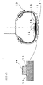
- the Fig. 1 is a diagram illustrating the tire equipped with the sensor according to the preferred embodiment 1.
- a numeral reference 11 denotes a tire tread
- 12 denotes a belt layer
- 13 denotes an inner liner portion of the tire
- 14 denotes a sensor which is attached to a rubber member 15 of a surface portion of the tire which is a rubber member of the inner liner portion 13
- 16 denotes an elastic adhesive layer for sticking the sensor to the rubber member 15 on the surface of the tire (hereafter, to be referred as "rubber member") .
- the elastic adhesive layer 16 is formed by curing the elastic adhesive that becomes elastic body after cure.
- the sensor 14 may be a sensor element such as a strain gauge or a piezoelectric element, a substrate on which a power supply for the sensor element, an amplifier and so on are mounted, a housing for receiving and protecting the sensor element and the substrate and a film for coating a reinforcement member for reinforcing them or the sensor.
- a room temperature moisture type adhesive containing any one of acrylic modified silicone resin, epoxy modified silicone resin, polychloroprene synthetic rubber or silylated urethane resin as a chief ingredient is preferably used.
- the elastic modulus of the elastic adhesive layer 16 preferably is in the range of 0.1 to 100 Mpa and loss coefficient (tan ⁇ ) thereof is preferably less than 0.1.
- loss coefficient (tan ⁇ ) thereof is preferably less than 0.1.
- the elastic modulus is less than 0.1 Mpa or tan ⁇ exceeds 0.1, though vibration and impact can be absorbed, deformation itself is large so that it is difficult to transmit deformation of the rubber member 15 to the sensor 14 precisely.
- the elastic modulus exceeds 100 Mpa, difference between stiffness of the elastic adhesive layer 16 and that of the rubber member 15 is large. This gives rise to problem in that the elastic adhesive layer brake away a tire rubber.
- the elastic modulus needless to say, it is required to use an elastic adhesive that hardly depends on temperature under condition within -40°C to 120 °C. Also, it is preferable that tan ⁇ hardly depends on temperature.
- the thickness of the elastic adhesive layer is equal to or less than 3 mm. In the case of that the thickness of the elastic adhesive layer exceeds 3 mm, the elastic adhesive layer itself is largely deformed. Thereby it is difficult to transmit the deformation of the rubber member 15 to the sensor accurately. On the other hand, it is requested for the elastic adhesive layer to have a thickness that it does not break. It is known that minimum value ⁇ of the thickness depends on a sensor length 1, a limit extension d of the elastic adhesive and maximum strain applied to the tire ⁇ . Therefore, regarding the minimum value ⁇ , factor of safety is set with respect to the limit extension d and value is set so as to satisfy following formula. ⁇ ⁇ ⁇ l ⁇ d 2 + 2 ⁇ ⁇ d
- a method of forming the elastic adhesive layer 16 is explained as follows. In order to keep the accuracy of the sensor detection, it is required to make the thickness of the elastic adhesive layer 16 of uniform.
- a frame (17) which is used for temporally blocking and has an area that an area of an opening thereof is larger than an area of the adhesive surface is provided on the rubber member 15 of the surface portion of the tire by a non-adhesion resin.
- the elastic adhesive is fed to in the frame 17 up to surface position of the frame 17. And then the sensor 14 is mounted thereon to cure the adhesive so that the adhesive layer having uniform thickness can be formed.
- a pattern may be formed on a mold and a bladder in curing the tire.
- the frame may be formed in curing the tire.
- a pit 18 may be provided thereon, as shown in Fig. 2(b) .
- the frame or the pit is formed at the same time to cure so that a position on which the elastic adhesive layer 16 is set accurately. Thereby, positioning of the sensor 14 can be performed readily and accurately.
- the elastic modulus of the elastic adhesive is equal to that of the surface portion of the tire of the rubber member 15 so that detection accuracy of the sensor 14 can be improved further.
- the correction coefficient must be calculated in accordance with its shape.
- a temperature sensor may be arranged in the vicinity of the sensor, in order to measure temperature change of the elastic modulus of the elastic adhesive or the sensor substrate. By measured temperature change of these elastic modulus, buffered correction coefficient may be calculated.
- frequency correction may be used with respect to sensor input frequency, together.
- the sensor 14 for detecting deformation of the tire 10 is adhered to the rubber member 15 on the surface portion of the tire.
- This adhering is performed by using the elastic adhesive composed of a room temperature moisture type adhesive containing any one of acrylic modified silicone resin, epoxy modified silicone resin, polychloroprene synthetic rubber or silylated urethane resin as a chief ingredient.
- the elastic adhesive layer 16 is formed.
- the elastic adhesive layer 16 is interposed between the sensor 14 and the rubber member 15 so that deformation of the tire 10 can be transmitted to the sensor 14 accurately and durability of the sensor 14 can be improved largely.
- the thickness of the elastic adhesive layer 16 is 3 mm or less while the adhesive that the elastic modulus is in the range of 0.1 to 1000 Mpa and loss coefficient (tan ⁇ ) is less than 0.1 is used so that deformation of the sensor 14 can be transmitted to the sensor 14 accurately and durability of the sensor 14 can be improved largely.
- the frame 17 or the pit 18 is mounted on the rubber member 15 of the surface portion of the tire and the elastic adhesive is fed in the frame 17 or the pit 18.
- the sensor is mounted on the frame 17 or the pit 18 to cure the adhesive so that the thickness of the elastic adhesive layer 16 becomes uniform certainly and deformation of the tire can be transmitted to the sensor 14 accurately.
- the case where the sensor 14 is attached to the rubber member 15 on the inner liner portion 13 of the tire is explained.
- the present invention should not limit to the case where the sensor 14 is attached to the surface portion of the rubber member inside of the tire.
- the sensor 14 may be attached to a surface portion of a rubber member outside of the tire such as a tire tread or a side portion.
- width and length of the elastic adhesive layer 16 is configured to be equal to width and length of the sensor 14. That is, the elastic adhesive layer 16 is provided on over the surface of the sensor 14.
- an area of a contact surface contacting a deformation part of the sensor 14 is 60 % or less of the area of the deformation part so that deformation of the rubber member 15 can be transmitted to the sensor 14 sufficiently.
- the whole sensor may be covered with a rubber sheet so as to reinforce adhesive performance between the sensor and the tire and prevent the sensor from contacting with the outside.
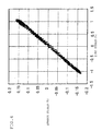
- a lateral axis indicates input strain (%) applied to the rubber piece 21. Since this input strain (%) corresponds to strain of the tire in vehicle running, it represents tire strain (%) in the Fig. 4 . Also, a vertical axis indicates sensor strain (%) which is ratio of output signal of the strain gauge 23 with respect to input. As clear from the Fig. 4 , magnitude of sensor strain (%) is 1/6 as many measurements as tire strain (%). Therefore, though magnitude of strain themselves was buffered, tire strain (%) and sensor strain (%) indicated high interrelation. Thereby, it was confirmed that deformation of the rubber member would be transmitted to the sensor accurately, through the elastic adhesive layer according to the present invention, which was formed by curing the adhesive.
- a frame as shown in the Fig. 2 was disposed in an interior of a tire. Additionally, a PET film on which a strain gauge is patterned under condition of the above Test of verifying accurately was adhered to the tire. Adhesion performance was verified by using a car equipped with the tire in 1000 km of distance. For comparison, the tire that the PET film was adhered by cyanoacrylate which is a quick-dry adhesive is used in the same test. As normal usage, cyanocarylate was applied as thinly as possible. In the result, according to the PET that was adhered by cyanoacrylate, adhesive-separation occurred at 100 km point.
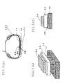
- the Fig.5(a) to (c) is schematic view of a method of attaching the piezoelectric element sensor to the tire equipped with the sensor according to the preferred embodiment 2.
- numeral 11 denotes the tire tread
- 12 denotes the belt layer
- 13 denotes the inner liner portion of the tire
- 34 is the piezoelectric element sensor attached to the rubber member 15 on the surface portion of the tire, which is the rubber member of the inner liner portion 13
- 35 denotes the sensor reinforcement member attached to the contact surface so as to cover the overall surface of the contact surface
- 36 denotes the elastic adhesive layer of sticking the piezoelectric element sensor 34 with the rubber member 15.
- the piezoelectric element sensor 34 comprises the piezoelectric element provided with the electrode and detects deformation amount of the tire.
- the elastic adhesive layer 36 is same adhesive layer as that of the adhesive layer 16 according to the preferred embodiment 1. Therefore, it is formed by curing the elastic adhesive that becomes the elastic body after cure.
- the sensor reinforcement member 35 a film-like member that stiffness of it is larger than that of the piezoelectric element sensor 34 and thickness of it is constant, while stiffness of the sensor reinforcement member 35 is set so that total stiffness of the sensor, which put the piezoelectric element sensor 34 together the sensor reinforcement member 35, becomes uniform. Stiffness of the piezoelectric element sensor 34 and the sensor reinforcement member 35 is represented by the product of thickness D and Young's modulus Y of each member.
- stiffness ratio ( D 2 ⁇ Y 2 )/( D 1 ⁇ Y 1 ) is 10 or more.
- the piezoelectric element sensor 34 since input to the piezoelectric element sensor 34 is buffered, durability of the piezoelectric element sensor 34, that is, durability of the tire equipped with the sensor 10P can be improved.
- tire input is high-frequency (i.e. wave length is short) and the reinforcement member is not used, as shown in the Fig. 6 (a) .
- local strain is input to the piezoelectric element sensor 34. If magnitude of the local strain is large, the piezoelectric element sensor 34 may be destructed.
- the sensor reinforcement member 35 is disposed so that total strain, which put the piezoelectric element sensor 34 together the sensor reinforcement member 35, can be uniform. Thereby, partial strain is not occurred in the piezoelectric element sensor 34. Therefore, durability of the piezoelectric element sensor 34 can be improved largely.
- piezoelectric element sensor 34 As the piezoelectric element used in the piezoelectric element sensor 34 according to this embodiment, well-known piezoelectric element sensor, such as lead zirconate titanate (PZT), barium titanate, quartz crystal, cadmium sulfide, polyvinylidene difluoride (PVDF) polyvinyl chloride and so on, may be used.
- PZT lead zirconate titanate
- PVDF polyvinylidene difluoride
- Gold, cupper or the like would be used as material constituting the electrode.
- soft material such as gold may preferably be subjected to a screen-printing on the piezoelectric element to form the electrode.
- a conductive rubber may be used as the material constituting the electrode.
- a film-like resin which has constant thickness, such as polyamide, polyester, polyimide, nylon, polytetrafluoroethylene, polyethylene, polypropylene, EVA, polyurethane or polyvinyl chloride is used.
- stiffness of the sensor reinforcement member 35 is 1 kN/m - 100 kN/m and loss coefficient is less than 0.1.
- stiffness of is less than 1 kN/m or loss coefficient (tan ⁇ ) exceeds 0.1, it is difficult to transmit deformation of the rubber member 15 to the piezoelectric element sensor 34 accurately, though effect of easing vibration and impact is large.
- stiffness exceeds 100 kN/m, since deformation of the sensor itself with respect to input is small, it is difficult to measure it accurately.
- stiffness needless to say, it is required to use a resin having small temperature dependency within -40 - 120 °C that is operating temperature range. Also, it is required that tan ⁇ having small temperature dependency. Any one of physical processing such as ultraviolet radiation-irradiation processing, corona discharge processing, plasma processing or the like, chemical processing that pharmaceutical used or mechanical processing, is performed in advance so that adhesive performance can be improved.
- An elastic adhesive for forming the adhesive layer 36 is the same as elastic adhesive according to the embodiment 1.
- the adhesive layer 36 has buffering effect with respect to vibration and impact.
- the elastic modulus of the elastic adhesive are in the range of 0.1 to 100 Mpa and loss coefficient (tan ⁇ ) is less 0.1.
- the thickness of the adhesive layer 36 is 3 mm or less, as the preferred embodiment 1. Therefore, when the thickness of the adhesive layer 36 exceeds 3 mm, deformation of the adhesive layer itself is large. Thereby, it is difficult to transmit deformation of the rubber member 15 to the piezoelectric element sensor 34 accurately.
- the thickness, the elastic modulus and tan ⁇ of the adhesive layer 36 is set as above so that deformation of the rubber member 15 can be transmitted to the piezoelectric element sensor 34 or the sensor reinforcement member 35 accurately and external vibration and impact can be absorbed.
- the sensor reinforcement member 35 and the adhesive layer 36 is disposed between the rubber member 15 and the piezoelectric element sensor 34 so as to buffer tire input. Therefore, when tire input is obtained, it is need to obtain tire input from the buffered tire input by using the elastic modulus of the sensor reinforcement member 35 and the adhesive layer 36.
- the width and length of the adhesive layer 36 and the sensor reinforce member 35 is set to be equal to the sensor width w and sensor length l, respectively.
- amount of input buffered by the sensor is disregarded, because it is small as compared with amount of input buffered by the sensor reinforcement member.
- temperature of the buffered correction coefficient may be corrected by arranging other temperature sensor.
- the sensor equipped with the sensor 10P including the piezoelectric element sensor 34 on the surface of the tire or in the interior of the tire has feature that the film-like member made of the polyester resin or the like, which covers the overall surface on the contact surface side contacting with the tire being the detection surface of the piezoelectric element sensor and has larger stiffness than that of the piezoelectric element sensor 34, is disposed, the sensor reinforcement member 35 is adhered to the rubber member 15 on the surface of the tire by using the adhesive which becomes the elastic body after cure and the sensor reinforcement member is intervened between the piezoelectric element sensor 34 and the rubber member 15. Thereby, stiffness of the whole sensor is large uniformly so that input to the piezoelectric element sensor 34 can be buffered effectively.
- the tire equipped with the sensor 10P having excellent durability. Also, there is provided the tire equipped with the sensor capable of detecting deformation of the tire, since the deformation of the rubber member 15 on the surface of the tire to the piezoelectric element sensor 34 certainly.
- the tire equipped with the sensor 10P including the piezoelectric element sensor 34 for detecting deformation of the tire.
- a piezoelectric element sensor generating electricity may be used.
- the piezoelectric element sensor 34 is attached to the inner liner portion 13.
- the present invention should not be limited to them.
- the piezoelectric element sensor may be arranged on the tire tread portion, a tire side as a side portion or the interior of the tire as the interior of the tread block.
- a surface opposite to the rubber member of the sensor reinforcement member 35 may be adhered to the tire member by using the adhesive which becomes the elastic body after cure. Also, a surface opposite to this surface or both of surfaces may be adhered to the tire member by using same elastic adhesive.
- a surface of a side contacting with the tire which is a detection surface of the piezoelectric element sensor 34, is wholly covered with the sensor reinforcement member 35.
- a surface opposite to the surface contacting with the tire of the sensor 34 may wholly be covered with the sensor reinforcement member 35.
- stiffness of the sensor reinforcement member 35 is larger than that of the piezoelectric element sensor 34.
- stiffness ratio is 10 or more, total stiffness of the piezoelectric sensor and the sensor reinforcement member becomes almost uniform.
- the adhesive which becomes the elastic body after cure and interpose the adhesive layer 36 used in the embodiment 1 between the piezoelectric element sensor and the rubber member 15, when the piezoelectric element sensor 34 is directly adhered to the rubber member 15.
- both of the surface contacting with the tire of the piezoelectric element sensor 34 and the surface opposite to it are covered with the sensor reinforce member 35m and 35n, respectively. Thereby, the same effect can be obtained.
- the sensor reinforcement member 35L formed by laminating the film-like resin 35a, 35b and 35c may be used.
- stiffness of the film-like resin 35a, 35b and 35c on a side that is near to the rubber member 15 of the surface portion of the tire is smaller than that on the side that is far away it. Thereby, the tire input can be buffered more effectively.
- the Fig. 7(c) it is important that stiffness of the film-like resin 35a, 35b and 35c on a side that is near to the rubber member 15 of the surface portion of the tire is smaller than that on the side that is far away it. Thereby, the tire input can be buffered more effectively.
- the sensor reinforcement member 35 (or the sensor reinforcement member 35L) is provided with the surface opposite to the detection surface of the piezoelectric element sensor 34 at least, and an electronic device for a radio communication such as an A-D converter 37a, a signal process circuit 37b, a radio circuit 37c or an antenna 37d is formed on the sensor reinforcement member 35 by a screen printing so that a piezoelectric element module in which a compact sensor and a radio are integrated can be obtained.
- an electronic device for a radio communication such as an A-D converter 37a, a signal process circuit 37b, a radio circuit 37c or an antenna 37d is formed on the sensor reinforcement member 35 by a screen printing so that a piezoelectric element module in which a compact sensor and a radio are integrated can be obtained.
- the lateral axis indicates inputting times and the vertical axis indicates survival rates of the piezoelectric element sensor.
- the graph all of piezoelectric sensors without the reinforcement have been failed before the test has been performed one million times.
- the piezoelectric element sensor covered with the polyester laminate according to the present invention has durability over 5 million times, it has been confirmed that the method of attaching the piezoelectric element sensor is used so that durability of the piezoelectric element sensor can be improved greatly.
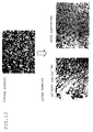
- the Fig. 10 is an enlarged photograph of the electrode of piezoelectric element sensor before and after running, when the tire equipped with the piezoelectric element sensor was placed under test running in an indoor tester at predetermined speed. After running, there are many cracks on the surface of the piezoelectric element sensor without the reinforcement. On the other hand, with respect to repeatedly inputting to the piezoelectric element sensor over 5 million times, there scarcely are cracks causing for failure thereon.
- the deformation of the rubber member on the surface of the tire can be transmitted to the sensor precisely and durability of the sensor can be improved largely. Therefore, deformation condition of the tire can be measured stably.
- running control of the vehicle is performed in accordance with such information, running safety of the vehicle can be enhanced.
- the present invention is applied to the piezoelectric sensor used as a driving power supply such as an acceleration sensor equipped with the tire, power is stably supplied over long term.
Landscapes
- Engineering & Computer Science (AREA)
- Mechanical Engineering (AREA)
- Physics & Mathematics (AREA)
- General Physics & Mathematics (AREA)
- Tires In General (AREA)
- Measurement Of Length, Angles, Or The Like Using Electric Or Magnetic Means (AREA)
Applications Claiming Priority (3)
| Application Number | Priority Date | Filing Date | Title |
|---|---|---|---|
| JP2006307517 | 2006-11-14 | ||
| JP2006307513 | 2006-11-14 | ||
| PCT/JP2007/072013 WO2008059838A1 (fr) | 2006-11-14 | 2007-11-13 | Pneu avec capteur et procédé pour mesurer le niveau de distorsion du pneu |
Publications (3)
| Publication Number | Publication Date |
|---|---|
| EP2085253A1 true EP2085253A1 (fr) | 2009-08-05 |
| EP2085253A4 EP2085253A4 (fr) | 2011-01-26 |
| EP2085253B1 EP2085253B1 (fr) | 2020-07-08 |
Family
ID=39401645
Family Applications (1)
| Application Number | Title | Priority Date | Filing Date |
|---|---|---|---|
| EP07831743.5A Active EP2085253B1 (fr) | 2006-11-14 | 2007-11-13 | Pneus avec capteur et procédés pour mesurer le niveau de déformation d'un pneu |
Country Status (4)
| Country | Link |
|---|---|
| US (1) | US8051705B2 (fr) |
| EP (1) | EP2085253B1 (fr) |
| JP (1) | JP5219829B2 (fr) |
| WO (1) | WO2008059838A1 (fr) |
Cited By (11)
| Publication number | Priority date | Publication date | Assignee | Title |
|---|---|---|---|---|
| WO2010092092A1 (fr) * | 2009-02-13 | 2010-08-19 | Commissariat A L'energie Atomique Et Aux Energies Alternatives | Capteur de force de contact |
| FR2944865A1 (fr) * | 2009-04-27 | 2010-10-29 | Commissariat Energie Atomique | Capteur de contrainte et son procede de realisation. |
| CN105980824A (zh) * | 2014-03-13 | 2016-09-28 | 米其林集团总公司 | 用于轮胎检查的传感器装置 |
| US10006835B2 (en) | 2014-03-13 | 2018-06-26 | Compagnie Generale Des Etablissements Michelin | Sensor device with magnet and sensor array for tire inspection |
| EP3495169A1 (fr) * | 2017-12-11 | 2019-06-12 | Kawasaki Jukogyo Kabushiki Kaisha | Système d'enregistrement d'informations de déplacement de véhicule à inclinaison, programme de traitement d'informations et dispositif d'enregistrement d'informations de déplacement |
| WO2019115497A1 (fr) * | 2017-12-15 | 2019-06-20 | Compagnie Generale Des Etablissements Michelin | Élément de montage destiné à recevoir un bandage pneumatique fermé et ensemble monté comportant un tel élément avec un système de surveillance de pression de gonflage |
| CN111094022A (zh) * | 2017-09-12 | 2020-05-01 | 住友橡胶工业株式会社 | 充气轮胎 |
| WO2021214388A1 (fr) * | 2020-04-22 | 2021-10-28 | Teknologian Tutkimuskeskus Vtt Oy | Objet comprenant un matériau élastomère et capteur de déformation comprenant un élastomère piézorésistif |
| EP3922486A1 (fr) * | 2020-06-08 | 2021-12-15 | Continental Reifen Deutschland GmbH | Pneus de véhicule |
| EP4047337A4 (fr) * | 2019-10-17 | 2023-11-22 | TDK Corporation | Dispositif de mesure et système de mesure |
| EP4610064A4 (fr) * | 2022-10-28 | 2025-12-10 | Astemo Ltd | Dispositif de détection de contrainte |
Families Citing this family (42)
| Publication number | Priority date | Publication date | Assignee | Title |
|---|---|---|---|---|
| DE102008012659B4 (de) * | 2007-04-16 | 2019-02-21 | Continental Teves Ag & Co. Ohg | Reifenmodul mit piezoelektrischem Wandler |
| JP2010533844A (ja) * | 2007-07-18 | 2010-10-28 | ピレリ・タイヤ・ソチエタ・ペル・アツィオーニ | 車両の走行中のタイヤの動作パラメータを決定するための方法およびシステム |
| JP5928935B2 (ja) * | 2008-08-29 | 2016-06-01 | カンパニー ジェネラレ デ エスタブリシュメンツ ミシュラン | 1‐dタイヤ用装置 |
| JP2010069828A (ja) * | 2008-09-22 | 2010-04-02 | Bridgestone Corp | タイヤ内面処理方法及びタイヤ内面処理装置 |
| CN102612443B (zh) * | 2009-09-01 | 2015-02-11 | 横滨橡胶株式会社 | 轮胎状态检测装置 |
| DE102011003134A1 (de) * | 2011-01-25 | 2012-07-26 | Bayerische Motoren Werke Aktiengesellschaft | Anordnung einer Reifendruck-Sensoreinheit |
| DE102011003712A1 (de) * | 2011-02-07 | 2012-08-09 | Bayerische Motoren Werke Aktiengesellschaft | Fahrzeug-Luftreifen mit einer Dichtmasse auf der Reifen-Innenseite |
| EP2719552B1 (fr) * | 2011-06-06 | 2019-04-24 | Bridgestone Corporation | Structure de montage |
| JP5681042B2 (ja) * | 2011-06-06 | 2015-03-04 | 株式会社ブリヂストン | 取付構造体 |
| JP5744630B2 (ja) * | 2011-06-06 | 2015-07-08 | 株式会社ブリヂストン | 取付構造体 |
| US8596117B2 (en) | 2011-10-03 | 2013-12-03 | Bridgestone Americas Tire Operations, Llc | Attachment patch for mounting various devices |
| JP2014025179A (ja) * | 2012-07-27 | 2014-02-06 | Yamaha Corp | 歪みセンサ付き手袋 |
| US8844346B1 (en) * | 2013-03-08 | 2014-09-30 | The Goodyear Tire & Rubber Company | Tire load estimation system using road profile adaptive filtering |
| US9815343B1 (en) * | 2014-06-06 | 2017-11-14 | Iowa State University Research Foundation, Inc. | Tire sensing method for enhanced safety and controllability of vehicles |
| FR3029356B1 (fr) * | 2014-12-01 | 2016-11-18 | Commissariat Energie Atomique | Dispositif a coque deformable comprenant un circuit interne piezoelectrique |
| WO2016099633A1 (fr) | 2014-12-19 | 2016-06-23 | Bridgestone Americas Tire Operations, Llc | Pièce de fixation pour monter des dispositifs |
| JP6422377B2 (ja) * | 2015-03-06 | 2018-11-14 | 株式会社ブリヂストン | ランフラットタイヤ |
| FR3034709B1 (fr) * | 2015-04-09 | 2017-04-14 | Michelin & Cie | Pneumatique muni d'un dispositif electronique |
| DE102015213157B4 (de) | 2015-07-14 | 2024-03-14 | Continental Reifen Deutschland Gmbh | Fahrzeug mit einem Reifenmodul |
| JP6629547B2 (ja) * | 2015-08-18 | 2020-01-15 | 株式会社ブリヂストン | ランフラットタイヤ |
| US9840118B2 (en) | 2015-12-09 | 2017-12-12 | The Goodyear Tire & Rubber Company | Tire sensor-based robust road surface roughness classification system and method |
| JP6587923B2 (ja) * | 2015-12-16 | 2019-10-09 | 株式会社ブリヂストン | タイヤ |
| WO2018005810A1 (fr) * | 2016-06-30 | 2018-01-04 | Bridgestone Americas Tire Operations, Llc | Procédés de traitement de revêtements internes, revêtements internes obtenus à partir de ceux-ci et pneus contenant de tels revêtements internes |
| JP6617666B2 (ja) * | 2016-09-07 | 2019-12-11 | 株式会社デンソー | タイヤマウントセンサ |
| US20170010185A1 (en) * | 2016-09-20 | 2017-01-12 | Caterpillar Inc. | Tire health monitoring system |
| EP4701393A2 (fr) | 2017-02-09 | 2026-02-25 | Nextinput, Inc. | Capteurs de force numériques intégrés et procédés de fabrication associés |
| US11243125B2 (en) | 2017-02-09 | 2022-02-08 | Nextinput, Inc. | Integrated piezoresistive and piezoelectric fusion force sensor |
| US11243126B2 (en) | 2017-07-27 | 2022-02-08 | Nextinput, Inc. | Wafer bonded piezoresistive and piezoelectric force sensor and related methods of manufacture |
| US11579028B2 (en) | 2017-10-17 | 2023-02-14 | Nextinput, Inc. | Temperature coefficient of offset compensation for force sensor and strain gauge |
| WO2019099821A1 (fr) * | 2017-11-16 | 2019-05-23 | Nextinput, Inc. | Atténuateur de force pour capteur de force |
| JP7192865B2 (ja) * | 2018-07-24 | 2022-12-20 | 横浜ゴム株式会社 | 空気入りタイヤ及びその製造方法 |
| CN112469577A (zh) * | 2018-07-24 | 2021-03-09 | 横滨橡胶株式会社 | 充气轮胎及其制造方法 |
| JP7162486B2 (ja) * | 2018-10-01 | 2022-10-28 | 株式会社ブリヂストン | 機能部品、機能部品のタイヤへの取り付け構造及びタイヤ |
| JPWO2020129953A1 (ja) * | 2018-12-17 | 2021-10-14 | アルプスアルパイン株式会社 | 複合圧電素子、タイヤ状態測定装置、タイヤセンサモジュール、タイヤセンサ装置、および圧電センサ |
| US10836223B1 (en) | 2019-12-17 | 2020-11-17 | The Goodyear Tire & Rubber Company | Encapsulated embedded tire sensor unit |
| US11938762B2 (en) | 2020-08-19 | 2024-03-26 | The Goodyear Tire & Rubber Company | Tire sensor attachment structure |
| CN116848368A (zh) * | 2021-03-16 | 2023-10-03 | 日立安斯泰莫株式会社 | 应变量检测装置、轮胎 |
| JP2023036443A (ja) * | 2021-09-02 | 2023-03-14 | 横浜ゴム株式会社 | タイヤ |
| US12459311B2 (en) * | 2021-10-30 | 2025-11-04 | Tdk Corporation | Devices and methods for overloading protection of piezoelectric material mounted on wheels |
| JP7695552B2 (ja) * | 2021-12-03 | 2025-06-19 | 横浜ゴム株式会社 | 加硫ゴム用接着剤組成物、及び、タイヤ |
| CN118541271A (zh) * | 2022-02-22 | 2024-08-23 | 日立安斯泰莫株式会社 | 应变检测装置 |
| CN115307534A (zh) * | 2022-07-14 | 2022-11-08 | 广东粤港澳大湾区黄埔材料研究院 | 一种轮胎应变监测传感器及其制备方法 |
Family Cites Families (18)
| Publication number | Priority date | Publication date | Assignee | Title |
|---|---|---|---|---|
| JP3626269B2 (ja) | 1996-02-29 | 2005-03-02 | 横浜ゴム株式会社 | トランスポンダ装着タイヤ |
| GB9726594D0 (en) * | 1997-12-17 | 1998-02-18 | Sumitomo Rubber Ind | Sensor for a pneumatic tyre |
| EP1219515B1 (fr) | 2000-06-23 | 2011-01-19 | Kabushiki Kaisha Bridgestone | Procede d'estimation de l'etat de marche d'un vehicule, dispositif d'estimation de l'etat de marche d'un vehicule, dispositif de commande de vehicule, et bandage de roue |
| JP4629246B2 (ja) | 2001-02-13 | 2011-02-09 | 株式会社ブリヂストン | タイヤ走行状態の検出方法とタイヤ走行状態検出装置、及び路面状態の推定方法と路面状態推定装置 |
| EP1519843B1 (fr) | 2002-07-09 | 2008-10-29 | Pirelli Tyre S.p.A. | Procede d'installation d'un dispositif sur la surface interne d'un pneu, et kit d'installation |
| SE0300127D0 (sv) * | 2003-01-17 | 2003-01-17 | Imego Ab | Indicator arrangement |
| JP4296917B2 (ja) | 2003-12-10 | 2009-07-15 | トヨタ自動車株式会社 | タイヤ状態推定装置およびタイヤ |
| WO2005067073A1 (fr) * | 2003-12-29 | 2005-07-21 | Pirelli Pneumatici S.P.A. | Procede et systeme pour produire de l'energie electrique a l'interieur d'un pneu de vehicule |
| JP4349151B2 (ja) * | 2004-02-26 | 2009-10-21 | トヨタ自動車株式会社 | 接触状態取得装置 |
| JP4680532B2 (ja) * | 2004-06-02 | 2011-05-11 | 株式会社ブリヂストン | タイヤの動的状態推定方法とその装置 |
| ATE490099T1 (de) | 2004-07-23 | 2010-12-15 | Silicon Valley Micro M Corp | Aussen angebrachtes reifendrucksensorsystem |
| JP3895347B2 (ja) | 2004-11-19 | 2007-03-22 | 横浜ゴム株式会社 | タイヤ変形量算出方法及びタイヤ変形量算出装置 |
| JP4241587B2 (ja) | 2004-11-25 | 2009-03-18 | トヨタ自動車株式会社 | 車輪状態監視装置および車輪状態監視方法 |
| JP2006193119A (ja) | 2005-01-17 | 2006-07-27 | Bridgestone Corp | タイヤ摩耗検知システム及び空気入りタイヤ |
| JP4487130B2 (ja) | 2005-04-13 | 2010-06-23 | 横浜ゴム株式会社 | 車輪横力算出方法および車輪横力算出装置 |
| JP4732788B2 (ja) | 2005-04-26 | 2011-07-27 | 株式会社ブリヂストン | 保護部材、電子式モニター装置及び空気入りタイヤ |
| JP5101497B2 (ja) * | 2005-06-10 | 2012-12-19 | コンパニー ゼネラール デ エタブリッスマン ミシュラン | 電子装置パッケージ・ハウジングに取り付けられている圧電センサの使用 |
| US7523656B1 (en) * | 2007-11-01 | 2009-04-28 | Infineon Technologies Ag | Tire sensor system and monitoring method |
-
2007
- 2007-11-13 WO PCT/JP2007/072013 patent/WO2008059838A1/fr not_active Ceased
- 2007-11-13 JP JP2008544151A patent/JP5219829B2/ja not_active Expired - Fee Related
- 2007-11-13 EP EP07831743.5A patent/EP2085253B1/fr active Active
- 2007-11-13 US US12/514,701 patent/US8051705B2/en not_active Expired - Fee Related
Cited By (19)
| Publication number | Priority date | Publication date | Assignee | Title |
|---|---|---|---|---|
| WO2010092092A1 (fr) * | 2009-02-13 | 2010-08-19 | Commissariat A L'energie Atomique Et Aux Energies Alternatives | Capteur de force de contact |
| FR2942316A1 (fr) * | 2009-02-13 | 2010-08-20 | Commissariat Energie Atomique | Capteur de force de contact |
| US8601885B2 (en) | 2009-02-13 | 2013-12-10 | Commissariat A L'energie Atomique Et Aux Energies Alternatives | Contact force sensor with an elastomer material secured to a deformable membrane |
| FR2944865A1 (fr) * | 2009-04-27 | 2010-10-29 | Commissariat Energie Atomique | Capteur de contrainte et son procede de realisation. |
| WO2010124993A1 (fr) * | 2009-04-27 | 2010-11-04 | Commissariat à l'énergie atomique et aux énergies alternatives | Capteur de contrainte et son procede de realisation |
| US10060832B2 (en) | 2014-03-13 | 2018-08-28 | Compagnie Generale Des Etablissements Michelin | Sensor device for tire inspection |
| EP3117199A4 (fr) * | 2014-03-13 | 2017-11-08 | Compagnie Générale des Etablissements Michelin | Dispositif de détection pour l'inspection de pneus |
| US10006835B2 (en) | 2014-03-13 | 2018-06-26 | Compagnie Generale Des Etablissements Michelin | Sensor device with magnet and sensor array for tire inspection |
| CN105980824A (zh) * | 2014-03-13 | 2016-09-28 | 米其林集团总公司 | 用于轮胎检查的传感器装置 |
| CN105980824B (zh) * | 2014-03-13 | 2019-04-12 | 米其林集团总公司 | 用于轮胎检查的传感器装置 |
| CN111094022A (zh) * | 2017-09-12 | 2020-05-01 | 住友橡胶工业株式会社 | 充气轮胎 |
| CN111094022B (zh) * | 2017-09-12 | 2022-01-14 | 住友橡胶工业株式会社 | 充气轮胎 |
| EP3495169A1 (fr) * | 2017-12-11 | 2019-06-12 | Kawasaki Jukogyo Kabushiki Kaisha | Système d'enregistrement d'informations de déplacement de véhicule à inclinaison, programme de traitement d'informations et dispositif d'enregistrement d'informations de déplacement |
| WO2019115497A1 (fr) * | 2017-12-15 | 2019-06-20 | Compagnie Generale Des Etablissements Michelin | Élément de montage destiné à recevoir un bandage pneumatique fermé et ensemble monté comportant un tel élément avec un système de surveillance de pression de gonflage |
| EP4047337A4 (fr) * | 2019-10-17 | 2023-11-22 | TDK Corporation | Dispositif de mesure et système de mesure |
| US12235102B2 (en) | 2019-10-17 | 2025-02-25 | Tdk Corporation | Measuring device and measuring system |
| WO2021214388A1 (fr) * | 2020-04-22 | 2021-10-28 | Teknologian Tutkimuskeskus Vtt Oy | Objet comprenant un matériau élastomère et capteur de déformation comprenant un élastomère piézorésistif |
| EP3922486A1 (fr) * | 2020-06-08 | 2021-12-15 | Continental Reifen Deutschland GmbH | Pneus de véhicule |
| EP4610064A4 (fr) * | 2022-10-28 | 2025-12-10 | Astemo Ltd | Dispositif de détection de contrainte |
Also Published As
| Publication number | Publication date |
|---|---|
| JPWO2008059838A1 (ja) | 2010-03-04 |
| WO2008059838A1 (fr) | 2008-05-22 |
| EP2085253B1 (fr) | 2020-07-08 |
| US8051705B2 (en) | 2011-11-08 |
| JP5219829B2 (ja) | 2013-06-26 |
| US20100043541A1 (en) | 2010-02-25 |
| EP2085253A4 (fr) | 2011-01-26 |
Similar Documents
| Publication | Publication Date | Title |
|---|---|---|
| EP2085253B1 (fr) | Pneus avec capteur et procédés pour mesurer le niveau de déformation d'un pneu | |
| RU2388621C2 (ru) | Сборка шины со встроенными устройствами для генерирования электроэнергии | |
| US7523656B1 (en) | Tire sensor system and monitoring method | |
| RU2377137C2 (ru) | Система для генерирования электрической энергии из механической энергии вращающейся шины | |
| JP4205102B2 (ja) | 車両タイヤ内に電気エネルギーを生成する方法及びシステム | |
| Matsuzaki et al. | Wireless strain monitoring of tires using electrical capacitance changes with an oscillating circuit | |
| US6637276B2 (en) | Tire sensor and method | |
| US9469167B2 (en) | Vehicle pneumatic tire having a sealing material on the inside of the tire | |
| EP0924112B1 (fr) | Capteur pour pneumatiques | |
| JP2005525265A (ja) | 補強された圧電材料を用いて回転するタイヤの機械的エネルギーから電力を発生させるシステム | |
| EP2508364A1 (fr) | Améliorations de ou associées à des systèmes micro-puissance pour un capteur de surveillance auto-alimenté en énergie | |
| US20190025157A1 (en) | Sensorized mechanical component | |
| JP2005156531A (ja) | 圧力センサおよび生体情報処理装置 | |
| KR20050063099A (ko) | 자가발전형 센싱 모듈 및 그것을 사용하는 타이어 공기압모니터링 시스템 | |
| CN101754873A (zh) | 用于在车轮轮胎内产生电能的方法和系统 | |
| Todoroki et al. | Wireless strain monitoring using electrical capacitance change of tire: part I—with oscillating circuit | |
| US20230139916A1 (en) | Smart roller | |
| US20080202657A1 (en) | Arrangement for Pressure Measurement | |
| EP4047337A1 (fr) | Dispositif de mesure et système de mesure | |
| WO2021177062A1 (fr) | Capteur monté sur pneu et support | |
| US20220090982A1 (en) | A stretchable bidirectional capacitive pressure sensor and method of use | |
| CN102171546A (zh) | 测量物理参数的方法和装置 | |
| US20080246372A1 (en) | Device and Method for Influencing Vibration of a Planar Element | |
| JP2006064565A (ja) | タイヤセンサユニット、タイヤ状態検出装置及びタイヤ | |
| JP4561500B2 (ja) | ワイヤレスひずみ測定システム |
Legal Events
| Date | Code | Title | Description |
|---|---|---|---|
| PUAI | Public reference made under article 153(3) epc to a published international application that has entered the european phase |
Free format text: ORIGINAL CODE: 0009012 |
|
| 17P | Request for examination filed |
Effective date: 20090515 |
|
| AK | Designated contracting states |
Kind code of ref document: A1 Designated state(s): AT BE BG CH CY CZ DE DK EE ES FI FR GB GR HU IE IS IT LI LT LU LV MC MT NL PL PT RO SE SI SK TR |
|
| DAX | Request for extension of the european patent (deleted) | ||
| A4 | Supplementary search report drawn up and despatched |
Effective date: 20101229 |
|
| 17Q | First examination report despatched |
Effective date: 20150422 |
|
| GRAP | Despatch of communication of intention to grant a patent |
Free format text: ORIGINAL CODE: EPIDOSNIGR1 |
|
| STAA | Information on the status of an ep patent application or granted ep patent |
Free format text: STATUS: GRANT OF PATENT IS INTENDED |
|
| INTG | Intention to grant announced |
Effective date: 20200124 |
|
| GRAS | Grant fee paid |
Free format text: ORIGINAL CODE: EPIDOSNIGR3 |
|
| GRAA | (expected) grant |
Free format text: ORIGINAL CODE: 0009210 |
|
| STAA | Information on the status of an ep patent application or granted ep patent |
Free format text: STATUS: THE PATENT HAS BEEN GRANTED |
|
| AK | Designated contracting states |
Kind code of ref document: B1 Designated state(s): AT BE BG CH CY CZ DE DK EE ES FI FR GB GR HU IE IS IT LI LT LU LV MC MT NL PL PT RO SE SI SK TR |
|
| REG | Reference to a national code |
Ref country code: GB Ref legal event code: FG4D |
|
| REG | Reference to a national code |
Ref country code: CH Ref legal event code: EP Ref country code: AT Ref legal event code: REF Ref document number: 1288070 Country of ref document: AT Kind code of ref document: T Effective date: 20200715 |
|
| REG | Reference to a national code |
Ref country code: DE Ref legal event code: R096 Ref document number: 602007060435 Country of ref document: DE |
|
| REG | Reference to a national code |
Ref country code: IE Ref legal event code: FG4D |
|
| REG | Reference to a national code |
Ref country code: LT Ref legal event code: MG4D |
|
| REG | Reference to a national code |
Ref country code: AT Ref legal event code: MK05 Ref document number: 1288070 Country of ref document: AT Kind code of ref document: T Effective date: 20200708 |
|
| REG | Reference to a national code |
Ref country code: NL Ref legal event code: MP Effective date: 20200708 |
|
| PG25 | Lapsed in a contracting state [announced via postgrant information from national office to epo] |
Ref country code: PT Free format text: LAPSE BECAUSE OF FAILURE TO SUBMIT A TRANSLATION OF THE DESCRIPTION OR TO PAY THE FEE WITHIN THE PRESCRIBED TIME-LIMIT Effective date: 20201109 Ref country code: BG Free format text: LAPSE BECAUSE OF FAILURE TO SUBMIT A TRANSLATION OF THE DESCRIPTION OR TO PAY THE FEE WITHIN THE PRESCRIBED TIME-LIMIT Effective date: 20201008 Ref country code: SE Free format text: LAPSE BECAUSE OF FAILURE TO SUBMIT A TRANSLATION OF THE DESCRIPTION OR TO PAY THE FEE WITHIN THE PRESCRIBED TIME-LIMIT Effective date: 20200708 Ref country code: GR Free format text: LAPSE BECAUSE OF FAILURE TO SUBMIT A TRANSLATION OF THE DESCRIPTION OR TO PAY THE FEE WITHIN THE PRESCRIBED TIME-LIMIT Effective date: 20201009 Ref country code: ES Free format text: LAPSE BECAUSE OF FAILURE TO SUBMIT A TRANSLATION OF THE DESCRIPTION OR TO PAY THE FEE WITHIN THE PRESCRIBED TIME-LIMIT Effective date: 20200708 Ref country code: LT Free format text: LAPSE BECAUSE OF FAILURE TO SUBMIT A TRANSLATION OF THE DESCRIPTION OR TO PAY THE FEE WITHIN THE PRESCRIBED TIME-LIMIT Effective date: 20200708 Ref country code: AT Free format text: LAPSE BECAUSE OF FAILURE TO SUBMIT A TRANSLATION OF THE DESCRIPTION OR TO PAY THE FEE WITHIN THE PRESCRIBED TIME-LIMIT Effective date: 20200708 Ref country code: FI Free format text: LAPSE BECAUSE OF FAILURE TO SUBMIT A TRANSLATION OF THE DESCRIPTION OR TO PAY THE FEE WITHIN THE PRESCRIBED TIME-LIMIT Effective date: 20200708 |
|
| PGFP | Annual fee paid to national office [announced via postgrant information from national office to epo] |
Ref country code: FR Payment date: 20201120 Year of fee payment: 14 Ref country code: DE Payment date: 20201119 Year of fee payment: 14 |
|
| PG25 | Lapsed in a contracting state [announced via postgrant information from national office to epo] |
Ref country code: LV Free format text: LAPSE BECAUSE OF FAILURE TO SUBMIT A TRANSLATION OF THE DESCRIPTION OR TO PAY THE FEE WITHIN THE PRESCRIBED TIME-LIMIT Effective date: 20200708 Ref country code: PL Free format text: LAPSE BECAUSE OF FAILURE TO SUBMIT A TRANSLATION OF THE DESCRIPTION OR TO PAY THE FEE WITHIN THE PRESCRIBED TIME-LIMIT Effective date: 20200708 Ref country code: IS Free format text: LAPSE BECAUSE OF FAILURE TO SUBMIT A TRANSLATION OF THE DESCRIPTION OR TO PAY THE FEE WITHIN THE PRESCRIBED TIME-LIMIT Effective date: 20201108 |
|
| PG25 | Lapsed in a contracting state [announced via postgrant information from national office to epo] |
Ref country code: NL Free format text: LAPSE BECAUSE OF FAILURE TO SUBMIT A TRANSLATION OF THE DESCRIPTION OR TO PAY THE FEE WITHIN THE PRESCRIBED TIME-LIMIT Effective date: 20200708 |
|
| REG | Reference to a national code |
Ref country code: DE Ref legal event code: R097 Ref document number: 602007060435 Country of ref document: DE |
|
| PG25 | Lapsed in a contracting state [announced via postgrant information from national office to epo] |
Ref country code: RO Free format text: LAPSE BECAUSE OF FAILURE TO SUBMIT A TRANSLATION OF THE DESCRIPTION OR TO PAY THE FEE WITHIN THE PRESCRIBED TIME-LIMIT Effective date: 20200708 Ref country code: IT Free format text: LAPSE BECAUSE OF FAILURE TO SUBMIT A TRANSLATION OF THE DESCRIPTION OR TO PAY THE FEE WITHIN THE PRESCRIBED TIME-LIMIT Effective date: 20200708 Ref country code: DK Free format text: LAPSE BECAUSE OF FAILURE TO SUBMIT A TRANSLATION OF THE DESCRIPTION OR TO PAY THE FEE WITHIN THE PRESCRIBED TIME-LIMIT Effective date: 20200708 Ref country code: CZ Free format text: LAPSE BECAUSE OF FAILURE TO SUBMIT A TRANSLATION OF THE DESCRIPTION OR TO PAY THE FEE WITHIN THE PRESCRIBED TIME-LIMIT Effective date: 20200708 Ref country code: EE Free format text: LAPSE BECAUSE OF FAILURE TO SUBMIT A TRANSLATION OF THE DESCRIPTION OR TO PAY THE FEE WITHIN THE PRESCRIBED TIME-LIMIT Effective date: 20200708 |
|
| PLBE | No opposition filed within time limit |
Free format text: ORIGINAL CODE: 0009261 |
|
| STAA | Information on the status of an ep patent application or granted ep patent |
Free format text: STATUS: NO OPPOSITION FILED WITHIN TIME LIMIT |
|
| 26N | No opposition filed |
Effective date: 20210409 |
|
| PG25 | Lapsed in a contracting state [announced via postgrant information from national office to epo] |
Ref country code: MC Free format text: LAPSE BECAUSE OF FAILURE TO SUBMIT A TRANSLATION OF THE DESCRIPTION OR TO PAY THE FEE WITHIN THE PRESCRIBED TIME-LIMIT Effective date: 20200708 Ref country code: SK Free format text: LAPSE BECAUSE OF FAILURE TO SUBMIT A TRANSLATION OF THE DESCRIPTION OR TO PAY THE FEE WITHIN THE PRESCRIBED TIME-LIMIT Effective date: 20200708 |
|
| REG | Reference to a national code |
Ref country code: CH Ref legal event code: PL |
|
| GBPC | Gb: european patent ceased through non-payment of renewal fee |
Effective date: 20201113 |
|
| PG25 | Lapsed in a contracting state [announced via postgrant information from national office to epo] |
Ref country code: LU Free format text: LAPSE BECAUSE OF NON-PAYMENT OF DUE FEES Effective date: 20201113 |
|
| REG | Reference to a national code |
Ref country code: BE Ref legal event code: MM Effective date: 20201130 |
|
| PG25 | Lapsed in a contracting state [announced via postgrant information from national office to epo] |
Ref country code: CH Free format text: LAPSE BECAUSE OF NON-PAYMENT OF DUE FEES Effective date: 20201130 Ref country code: SI Free format text: LAPSE BECAUSE OF FAILURE TO SUBMIT A TRANSLATION OF THE DESCRIPTION OR TO PAY THE FEE WITHIN THE PRESCRIBED TIME-LIMIT Effective date: 20200708 Ref country code: LI Free format text: LAPSE BECAUSE OF NON-PAYMENT OF DUE FEES Effective date: 20201130 |
|
| PG25 | Lapsed in a contracting state [announced via postgrant information from national office to epo] |
Ref country code: IE Free format text: LAPSE BECAUSE OF NON-PAYMENT OF DUE FEES Effective date: 20201113 |
|
| PG25 | Lapsed in a contracting state [announced via postgrant information from national office to epo] |
Ref country code: GB Free format text: LAPSE BECAUSE OF NON-PAYMENT OF DUE FEES Effective date: 20201113 |
|
| PG25 | Lapsed in a contracting state [announced via postgrant information from national office to epo] |
Ref country code: IS Free format text: LAPSE BECAUSE OF FAILURE TO SUBMIT A TRANSLATION OF THE DESCRIPTION OR TO PAY THE FEE WITHIN THE PRESCRIBED TIME-LIMIT Effective date: 20201108 Ref country code: TR Free format text: LAPSE BECAUSE OF FAILURE TO SUBMIT A TRANSLATION OF THE DESCRIPTION OR TO PAY THE FEE WITHIN THE PRESCRIBED TIME-LIMIT Effective date: 20200708 Ref country code: MT Free format text: LAPSE BECAUSE OF FAILURE TO SUBMIT A TRANSLATION OF THE DESCRIPTION OR TO PAY THE FEE WITHIN THE PRESCRIBED TIME-LIMIT Effective date: 20200708 Ref country code: CY Free format text: LAPSE BECAUSE OF FAILURE TO SUBMIT A TRANSLATION OF THE DESCRIPTION OR TO PAY THE FEE WITHIN THE PRESCRIBED TIME-LIMIT Effective date: 20200708 |
|
| REG | Reference to a national code |
Ref country code: DE Ref legal event code: R119 Ref document number: 602007060435 Country of ref document: DE |
|
| PG25 | Lapsed in a contracting state [announced via postgrant information from national office to epo] |
Ref country code: BE Free format text: LAPSE BECAUSE OF NON-PAYMENT OF DUE FEES Effective date: 20201130 |
|
| PG25 | Lapsed in a contracting state [announced via postgrant information from national office to epo] |
Ref country code: DE Free format text: LAPSE BECAUSE OF NON-PAYMENT OF DUE FEES Effective date: 20220601 |
|
| PG25 | Lapsed in a contracting state [announced via postgrant information from national office to epo] |
Ref country code: FR Free format text: LAPSE BECAUSE OF NON-PAYMENT OF DUE FEES Effective date: 20211130 |