EP2085263A1 - Fahrzeugsitz mit kapazitivem Insassenerkennungssystem - Google Patents
Fahrzeugsitz mit kapazitivem Insassenerkennungssystem Download PDFInfo
- Publication number
- EP2085263A1 EP2085263A1 EP08150864A EP08150864A EP2085263A1 EP 2085263 A1 EP2085263 A1 EP 2085263A1 EP 08150864 A EP08150864 A EP 08150864A EP 08150864 A EP08150864 A EP 08150864A EP 2085263 A1 EP2085263 A1 EP 2085263A1
- Authority
- EP
- European Patent Office
- Prior art keywords
- node
- switch
- heating element
- seat
- arrangement
- Prior art date
- Legal status (The legal status is an assumption and is not a legal conclusion. Google has not performed a legal analysis and makes no representation as to the accuracy of the status listed.)
- Withdrawn
Links
- 238000001514 detection method Methods 0.000 title claims abstract description 26
- 238000010438 heat treatment Methods 0.000 claims abstract description 103
- 238000005259 measurement Methods 0.000 claims description 29
- 230000002950 deficient Effects 0.000 description 12
- 230000008878 coupling Effects 0.000 description 9
- 238000010168 coupling process Methods 0.000 description 9
- 238000005859 coupling reaction Methods 0.000 description 9
- 230000005684 electric field Effects 0.000 description 7
- 238000010586 diagram Methods 0.000 description 5
- 239000013256 coordination polymer Substances 0.000 description 3
- 230000000694 effects Effects 0.000 description 3
- 238000011144 upstream manufacturing Methods 0.000 description 3
- 230000008901 benefit Effects 0.000 description 2
- 239000012777 electrically insulating material Substances 0.000 description 2
- 239000000758 substrate Substances 0.000 description 2
- 239000004753 textile Substances 0.000 description 2
- 239000012876 carrier material Substances 0.000 description 1
- 238000006073 displacement reaction Methods 0.000 description 1
- 239000004744 fabric Substances 0.000 description 1
- 229920005570 flexible polymer Polymers 0.000 description 1
- 230000010354 integration Effects 0.000 description 1
- 239000007788 liquid Substances 0.000 description 1
- 239000000463 material Substances 0.000 description 1
- 230000007246 mechanism Effects 0.000 description 1
- 238000000034 method Methods 0.000 description 1
- 239000004745 nonwoven fabric Substances 0.000 description 1
- 230000003071 parasitic effect Effects 0.000 description 1
- 230000037361 pathway Effects 0.000 description 1
- 229920000642 polymer Polymers 0.000 description 1
- 230000009467 reduction Effects 0.000 description 1
- 230000004044 response Effects 0.000 description 1
- 230000035945 sensitivity Effects 0.000 description 1
- 125000006850 spacer group Chemical group 0.000 description 1
- 239000002759 woven fabric Substances 0.000 description 1
Images



Classifications
-
- B—PERFORMING OPERATIONS; TRANSPORTING
- B60—VEHICLES IN GENERAL
- B60N—SEATS SPECIALLY ADAPTED FOR VEHICLES; VEHICLE PASSENGER ACCOMMODATION NOT OTHERWISE PROVIDED FOR
- B60N2/00—Seats specially adapted for vehicles; Arrangement or mounting of seats in vehicles
- B60N2/56—Heating or ventilating devices
- B60N2/5678—Heating or ventilating devices characterised by electrical systems
- B60N2/5685—Resistance
-
- B—PERFORMING OPERATIONS; TRANSPORTING
- B60—VEHICLES IN GENERAL
- B60N—SEATS SPECIALLY ADAPTED FOR VEHICLES; VEHICLE PASSENGER ACCOMMODATION NOT OTHERWISE PROVIDED FOR
- B60N2/00—Seats specially adapted for vehicles; Arrangement or mounting of seats in vehicles
- B60N2/002—Seats provided with an occupancy detection means mounted therein or thereon
- B60N2/0021—Seats provided with an occupancy detection means mounted therein or thereon characterised by the type of sensor or measurement
- B60N2/0035—Seats provided with an occupancy detection means mounted therein or thereon characterised by the type of sensor or measurement characterised by the sensor data transmission, e.g. wired connections or wireless transmitters therefor; characterised by the sensor data processing, e.g. seat sensor signal amplification or electric circuits for providing seat sensor information
-
- B—PERFORMING OPERATIONS; TRANSPORTING
- B60—VEHICLES IN GENERAL
- B60R—VEHICLES, VEHICLE FITTINGS, OR VEHICLE PARTS, NOT OTHERWISE PROVIDED FOR
- B60R21/00—Arrangements or fittings on vehicles for protecting or preventing injuries to occupants or pedestrians in case of accidents or other traffic risks
- B60R21/01—Electrical circuits for triggering passive safety arrangements, e.g. airbags, safety belt tighteners, in case of vehicle accidents or impending vehicle accidents
- B60R21/015—Electrical circuits for triggering passive safety arrangements, e.g. airbags, safety belt tighteners, in case of vehicle accidents or impending vehicle accidents including means for detecting the presence or position of passengers, passenger seats or child seats, and the related safety parameters therefor, e.g. speed or timing of airbag inflation in relation to occupant position or seat belt use
- B60R21/01512—Passenger detection systems
- B60R21/0153—Passenger detection systems using field detection presence sensors
- B60R21/01532—Passenger detection systems using field detection presence sensors using electric or capacitive field sensors
-
- G—PHYSICS
- G01—MEASURING; TESTING
- G01G—WEIGHING
- G01G19/00—Weighing apparatus or methods adapted for special purposes not provided for in the preceding groups
- G01G19/40—Weighing apparatus or methods adapted for special purposes not provided for in the preceding groups with provisions for indicating, recording, or computing price or other quantities dependent on the weight
- G01G19/413—Weighing apparatus or methods adapted for special purposes not provided for in the preceding groups with provisions for indicating, recording, or computing price or other quantities dependent on the weight using electromechanical or electronic computing means
- G01G19/414—Weighing apparatus or methods adapted for special purposes not provided for in the preceding groups with provisions for indicating, recording, or computing price or other quantities dependent on the weight using electromechanical or electronic computing means using electronic computing means only
- G01G19/4142—Weighing apparatus or methods adapted for special purposes not provided for in the preceding groups with provisions for indicating, recording, or computing price or other quantities dependent on the weight using electromechanical or electronic computing means using electronic computing means only for controlling activation of safety devices, e.g. airbag systems
-
- B—PERFORMING OPERATIONS; TRANSPORTING
- B60—VEHICLES IN GENERAL
- B60N—SEATS SPECIALLY ADAPTED FOR VEHICLES; VEHICLE PASSENGER ACCOMMODATION NOT OTHERWISE PROVIDED FOR
- B60N2210/00—Sensor types, e.g. for passenger detection systems or for controlling seats
- B60N2210/10—Field detection presence sensors
- B60N2210/12—Capacitive; Electric field
-
- B—PERFORMING OPERATIONS; TRANSPORTING
- B60—VEHICLES IN GENERAL
- B60N—SEATS SPECIALLY ADAPTED FOR VEHICLES; VEHICLE PASSENGER ACCOMMODATION NOT OTHERWISE PROVIDED FOR
- B60N2230/00—Communication or electronic aspects
- B60N2230/30—Signal processing of sensor data
Definitions
- the present invention generally relates to a capacitive occupant detection system for a vehicle seat equipped with a seat heater element.
- the transmit electrode In the "shunt mode", an oscillating voltage signal is applied to the transmit electrode, building up an electric field to a receive electrode, and the displacement current induced at the receive electrode, which is influenced by the body being sensed, is measured. In the “transmit mode”, the transmit electrode is put in contact with the user's body, which then becomes a transmitter relative to a receiver, either by direct electrical connection or via capacitive coupling. "Shunt mode” is alternatively referred to as "coupling mode”.
- sensing electrode The electrode whose capacitance to ground or another electrode of the system is determined is herein referred to as "sensing electrode”. It should be noted that capacitance may be determined in various ways, e.g. by measuring amplitude and phase of the current flowing in the sensing electrode, the charging time of the sensing electrode, and the like.
- the to be determined capacitance of the sensing electrode is influenced by conductive elements in the vicinity of the sensing electrode.
- conductive elements in the vicinity of the sensing electrode.
- the driven shield electrode hereinafter referred to as "shielding electrode”
- the sensing electrode are kept at substantially the same electric potential so that the electric field between the sensing electrode and the driven shield electrode substantially cancels.
- Vehicle seats may be equipped with seat heaters to increase the occupant's comfort when driving in cold weather conditions.
- seat heaters normally comprise one or more electrical heating elements, integrated in the seating portion, the side bolsters and/or the seat backrest, which dissipate heat when a current is caused to flow therein.
- Such heating elements represent conductive structures, which influence the electrical field of a capacitive sensing system and thus the measurements performed by that system.
- the latter are arranged deeper within the seat than the electrodes of the capacitive sensing system, with the shielding electrode being interposed between the sensing electrode and the heating elements.
- the drawback of such an arrangement is that the heating of the seat surface becomes less effective, first, because of the increased distance to the seat surface and, second, because of the additional heat shielding effect of the electrode arrangement.
- the present invention proposes an arrangement comprising a vehicle seat in combination with a seat heater and a capacitive occupant detection system.
- the seat heater comprises a seat heating element disposed in the vehicle seat while the capacitive occupant detection system comprises an electrode arrangement also disposed in the vehicle seat.
- the electrode arrangement includes a sensing electrode and a shielding electrode.
- the seat heating element is closest to the seating region of the vehicle seat and the sensing electrode is arranged between the seat heating element and the shielding electrode.
- the disposition of the heating element closest to the surface of the vehicle seat which comes into contact with the occupant greatly enhances the efficiency of the seat heater, reduces the time for the occupant to feel the warmth of the seat and thus increases the occupant's seating comfort in cold weather conditions.
- the seat heater may be operatively connected to the same electric potential as the shielding electrode or the sensing electrode, with the effect of reducing the capacitive coupling between the sensing electrode and the seat heating element: the seat heating element is said to be made "invisible" for the sensing electrode or is used as a part of the sensing electrode.
- the seat heater comprises a current source (as used herein this term may designate an ideal current source, a voltage source, a battery, etc.) and a current sink (e.g. the second terminal of the current source or ground). Both current source and current sink can but need not be arranged within the vehicle seat.
- the seat heating element may be operatively connected to the current source via a first node and to the current sink via a second node.
- the capacitive occupant detection system preferably comprises a capacitive measurement circuit, to which the sensing electrode and the shielding electrode are operatively connected via a third node and a fourth node, respectively.
- an electrically controllable switching arrangement is provided, which comprises
- switching states of the switching arrangement are configured in such a way as to be able to be put into at least the following switching states:
- the arrangement comprises an integrity check circuit, the integrity check circuit including a DC voltage source, a current measuring means, such as a current meter and an electrically controllable fifth switch, the DC voltage source being operatively connected to the fourth node via the fifth switch and the current measuring means being arranged so as to measure current flowing through the fifth switch when the fifth switch is in closed state.
- the seat heating element is electrically connected to the shielding or the sensing electrode when the capacitive measurement is made, it is preferably treated as a safety-relevant component.
- the integrity check circuit possibly in combination with some of the components discussed hereinafter, allows detecting short-circuits (e.g. caused by liquid spilled on the seat) and/or line interruptions, (e.g.
- the arrangement comprises an electrically controllable sixth switch arranged between the third and fourth nodes, the sixth switch having a closed state, in which the third node is connected to the fourth node.
- a first resistor having a resistance exceeding the nominal resistance of the seat heating element by a factor of at least 100, preferably of at least 400, is connected between the second node and ground.
- the arrangement may also comprise a second resistor, having a resistance exceeding the nominal resistance of the seat heating element by a factor of at least 100 preferably of at least 400, connected between the first node and ground.
- a third resistor is provided, which is connected between the first and second nodes in parallel to the seat heating element, and which has a resistance exceeding the nominal resistance of the seat heating element by a factor of at least 100, preferably of at least 400.
- the a first diode is connected between the first node and the parallel connection of the third resistor and the seat heating element, and a second diode is connected between the second node and the parallel connection of the third resistor and the seat heating element, the forward directions of the first and second diode being from current source to current sink, so that the heating current is allowed to flow through the seat heating element if the first and second switches are closed.
- an electrically controllable seventh switch is connected between the third node and the parallel connection of the third resistor and the seat heating element.
- the seventh switch is closed, while the first, second, third, fourth, fifth and sixth switches are open, the seat heating element is shorted to the sensing electrode for the capacitive measurement.
- the seat heating element is thus used as an extension of the sensing electrode.
- Fig. 1 schematically shows the arrangement of a seat heating element 10, a sensing electrode 12 and a shielding electrode 14 within the seating portion 16 of a vehicle seat 18.
- the seat heating element 10 is arranged closest to the upper surface of the seating portion 16.
- the seat heating element 10 is arranged in or directly below the seat trim. The deeper the seat heating element 10 is disposed in the seat, the more seat material will have to be heated up before the occupant 20 perceives the warmth of the seat. Accordingly, the present invention has the advantage of bringing the seating surface of the vehicle to a comfortable temperature in a shorter time than conventional systems in which the seat heating element 10 is arranged below the shielding electrode 14.
- the sensing electrode 12 is arranged deeper in the vehicle seat 18 (as seen from the seating surface) than the seat heating element 10 but less deep than the shielding electrode 14, which shields the sensing electrode 12 against the influence of the seat frame or any other conductive body behind the shielding electrode 14.
- the gaps between the seat heating element, the sensing electrode 12 and the shielding electrode 14 are not to scale in the drawing.
- the sensing electrode 12 and the shielding electrode 14 are arranged as conductive layers on the opposite sides of a common substrate of electrically insulating material, such as, for instance, a flexible polymer carrier film.
- the electrodes 12 and 14 could also be made of conductive textile, separated from one another by an electrically insulating textile spacer layer, e.g.
- each one of the electrodes 12 and 14 may be provided as a conductive layer on an individual substrate, the electrodes 12, 14 being spaced from one another by one or more layers of electrically insulating material which may be foamed sheets, sheets made of woven or non-woven fabric, polymer sheets, etc.
- the seat heating element 10 it may comprise resistive fibres, one or more resistive traces on a suitable carrier material, be present in form of a heating cable, etc.
- the seat heating element 10 and the electrodes 12 and 14 may be provided as separate components, which are put together at the assembly of the vehicle seat. More preferably, the seat heating element 10 and the electrodes 12 and 14 are provided as a constructional unit, which is ready for integration into the vehicle seat.
- Fig. 2 shows the schematic circuit diagram of a seat heater, a capacitive occupant detection system and an integrity check circuit 20 according to a first preferred variant of the invention.
- the seat heater comprises a power supply 22 providing a current source and a current sink to which the seat heating element 10 is operatively connected.
- the capacitive occupant detection system comprises the sensing electrode 12 and the shielding electrode 14 as well as a capacitive measurement circuit (not shown in the figures) to which the electrodes 12 and 14 are operatively connected.
- the arrangement further comprises an integrity check circuit 20 for finding circuit interruptions or short circuits.
- reference signs referring to a switch will be in the form "SX", where X denotes the number of the switch.
- the first switch may thus be denoted as “first switch S1", “switch S1” or, in short, simply “S1".
- the same convention is used for the nodes, whose reference signs will have the form “NX”, the resistors, whose reference signs will have the form “RX”, and the diodes, whose reference signs will have the form “DX”, X designating each time the number of the item in question used also in the general description and the claims.
- the reference sign of a resistor may also be used herein to denote the resistance value of the resistor. It should be noted that for the purposes of the present, ordinal numbers are only used for conveniently distinguishing between the various switches, resistors and nodes, not for indicating an order of importance or the like.
- the seat heating element 10 is connected to the power source via switches S1 and S2 of an electrically controllable switching arrangement.
- S1 and S2 are arranged between the current source and the seat heating element 10, and between the current sink and the seat heating element 10, respectively. More precisely, switch S1 is arranged between a first node N1 located upstream (with respect to the sense of the heating current) of the seat heating element 10 and the current source.
- Switch S2 is arranged between a second node N2 located downstream of the seat heating element 10 and the current sink. When both S1 and S2 are closed, the heating current may flow through the seat heating element 10, which thus dissipates heat and raises the temperature of the seating surface.
- the sensing electrode 12 is connected to the capacitive measurement circuit via a third node N3, while the shielding electrode is connected to the capacitive measurement circuit via fourth node N4.
- the capacitive measurement circuit is not shown in the drawings but the arrows to the left of nodes N3 and N4 indicate where it is to be connected.
- the switching arrangement further comprises third and fourth switches S3, S4. Switch S3 connects, when in closed state, node N1 to the node N4, whereas S4 connects, when in closed state, node N2 to node N4. When S1 and S2 are open while S3 and S4 are closed, the system is in condition for capacitive occupant detection.
- the measurement circuit then applies an oscillating voltage to the shielding electrode 14.
- An amplifier circuit of the capacitive measurement circuit applies to the sensing electrode 12 a voltage that corresponds to the shielding electrode voltage in both amplitude and phase.
- the capacitive measurement circuit measures the current that flows into the sensing electrode 12 in response to the oscillating voltage being applied to it, or (additionally or alternatively) a current induced in another electrode (a so-called "receive electrode", not shown in the drawings) of the capacitive sensing system.
- the seat heating element 14 acts as part of the shielding electrode 14 when the capacitive measurement is carried out.
- the seat heating element 10 and the sensing electrode are on substantially the same electrical potential during this measurement, there is no or only an insignificant electrical field between them: Accordingly, the seat heating element is "invisible" for the sensing electrode. Nevertheless, the seat heating element 10 reduces capacitive coupling between the sensing electrode 12 and an occupant or an item placed on the vehicle seat. The reduction in capacitive coupling depends mainly on the geometry of the seat heating element 10. If the shielding effect of a given seat heating element would be too important for reliable occupant detection, one should consider using the configurations of Figs. 3 or 4 , which are discussed in detail below.
- the integrity check circuit 20 comprises a DC voltage source (delivering a certain voltage Ug), a current meter 25 and switch S5, which are connected in series between the node N4 and ground. It further comprises a switch S6, which interconnects, in closed state, the nodes N3 and N4.
- the arrangement further comprises a first resistor R1, connected between N2 and ground and a second resistor R2 connected between N1 and ground.
- the resistance values of R1 and R2 are much higher (e.g. 1 k ⁇ ) than the resistance value of the seat heating element (typically a few ⁇ , e.g. 2.5 ⁇ ), so that they do not significantly affect seat heating operation when switches S1 and S2 are closed.
- the resistance values of R1 and R2 are sufficiently low, so that a measurable current flows through them when the switches S3, S4 and S5 are closed (while the others are open).
- the integrity check circuit 20 is used to identify short circuits or circuit interruptions in the system. For the rest of the description, we will assume that the resistance values of R1 and R2 are equal and that the resistance of the seat heater can be neglected when compared to these values.
- a check sequence may have the following form:
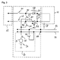
- Fig. 3 shows the schematic circuit diagram of a seat heater, a capacitive occupant detection system and an integrity check circuit according to a second preferred variant of the invention.
- the circuit diagram of this variant is very similar to the one discussed beforehand and the details relating to the connection of the seat heating element and the electrodes need not be repeated.
- the arrangement of Fig. 3 comprises a third resistor R3 connected in parallel to the seat heating element, a first diode D1 connected downstream (with respect to the sense of the heating current) of the first node N1 and upstream of the parallel connection of R3 and the seat heating element 10, and a second diode connected upstream of the second node N2 and downstream of the of the parallel connection of R3 and the seat heating element 10.
- Fig. 3 shows the schematic circuit diagram of a seat heater, a capacitive occupant detection system and an integrity check circuit according to a second preferred variant of the invention.
- the circuit diagram of this variant is very similar to the one discussed beforehand and the details relating to the connection of the seat heating element and
- the second resistor R2 has been omitted.
- the resistance value of R3 is chosen substantially higher than the resistance value of the seat heating element 10, so that only an insignificant part of the heating current is deviated through R3.
- the diodes D1 and D2 are chosen such that their capacitance CD is substantially smaller than the parasitic capacitance CP between the sensing electrode 12 and the seat heating element: CP>>2 CD.
- the seat heating element 10 acts as part of the capacitive measurement system and does not shield the sensing electrode from the occupant or the occupying item placed on the vehicle seat.
- the integrity check circuit 20 is again used to identify short circuits or circuit interruptions in the system.
- a check sequence may have the following form:
- Fig. 4 shows the schematic circuit diagram of a seat heater, a capacitive occupant detection system and an integrity check circuit according to a third preferred variant of the invention.
- the circuit diagram of this variant is again very similar to the ones discussed beforehand.
- the arrangement of Fig. 4 comprises a seventh switch S7 arranged between diode D2 and the parallel connection of the seat heating element and R3.
- S1, S2, S5 and S6 are open, while S3, S4 and S7 are closed.
- the seat heating element 10 thus thus operates as part of the sensing electrode 12, while the nodes N1 and N2 are connected to the shielding electrode. Since the voltage on the sensing electrode 12 (and in this case the seat heating element) is kept at substantially the same potential as the shielding electrode during the capacitive measurement, the capacitance CD of the diodes D1 and D2 does not significantly affect the measurement.
- the integrity check may be effected as the following sequence:
- the electrically controllable switching arrangement is controlled by the capacitive measurement circuit or a control unit common to the capacitive measurement circuit and the switching arrangement.
- the capacitive measurement circuit, the switching arrangement and the common control unit are preferably integrated as an application-specific integrated circuit (ASIC), a field programmable gate array (FPGA), a digital signal processor (DSP) or the like.Such capacitive measurement circuit or control unit common to the capacitive measurement circuit and the switching arrangement may also be used to control operation of the seat heater.
Landscapes
- Engineering & Computer Science (AREA)
- Physics & Mathematics (AREA)
- Mechanical Engineering (AREA)
- Mathematical Physics (AREA)
- Theoretical Computer Science (AREA)
- Aviation & Aerospace Engineering (AREA)
- Transportation (AREA)
- Computer Networks & Wireless Communication (AREA)
- General Physics & Mathematics (AREA)
- Seats For Vehicles (AREA)
Priority Applications (3)
| Application Number | Priority Date | Filing Date | Title |
|---|---|---|---|
| EP08150864A EP2085263A1 (de) | 2008-01-31 | 2008-01-31 | Fahrzeugsitz mit kapazitivem Insassenerkennungssystem |
| US12/865,137 US8493079B2 (en) | 2008-01-31 | 2009-01-21 | Vehicle seat with capacitive occupant detection system |
| PCT/EP2009/050631 WO2009095340A1 (en) | 2008-01-31 | 2009-01-21 | Vehicle seat with capacitive occupant detection system |
Applications Claiming Priority (1)
| Application Number | Priority Date | Filing Date | Title |
|---|---|---|---|
| EP08150864A EP2085263A1 (de) | 2008-01-31 | 2008-01-31 | Fahrzeugsitz mit kapazitivem Insassenerkennungssystem |
Publications (1)
| Publication Number | Publication Date |
|---|---|
| EP2085263A1 true EP2085263A1 (de) | 2009-08-05 |
Family
ID=39651006
Family Applications (1)
| Application Number | Title | Priority Date | Filing Date |
|---|---|---|---|
| EP08150864A Withdrawn EP2085263A1 (de) | 2008-01-31 | 2008-01-31 | Fahrzeugsitz mit kapazitivem Insassenerkennungssystem |
Country Status (3)
| Country | Link |
|---|---|
| US (1) | US8493079B2 (de) |
| EP (1) | EP2085263A1 (de) |
| WO (1) | WO2009095340A1 (de) |
Cited By (9)
| Publication number | Priority date | Publication date | Assignee | Title |
|---|---|---|---|---|
| WO2011063136A3 (en) * | 2009-11-19 | 2011-09-15 | Tk Holdings Inc. | Occupant detection and classification system |
| LU91739B1 (en) * | 2010-09-23 | 2012-03-26 | Iee Sarl | Capacitive occupant detection system |
| JP2012510407A (ja) * | 2008-12-03 | 2012-05-10 | イリノイ トゥール ワークス インコーポレイティド | 座席ヒーター乗員センサーアンテナ装置 |
| LU91791B1 (en) * | 2011-02-21 | 2012-08-22 | Iee Sarl | Heating element operated as capacitive sensing electrode |
| WO2014055266A1 (en) * | 2012-10-02 | 2014-04-10 | Tk Holdings Inc. | Occupant detection and classification system |
| US9278629B2 (en) | 2009-11-19 | 2016-03-08 | Tk Holdings Inc. | Occupant detection and classification system |
| LU92542B1 (en) * | 2014-09-10 | 2016-03-11 | Iee Sarl | Capacitive occupancy or proximity detector |
| CN106062521A (zh) * | 2014-02-17 | 2016-10-26 | Iee国际电子工程股份公司 | 乘员传感器及具有这种乘员传感器的座椅 |
| DE112012000943B4 (de) | 2011-02-22 | 2023-03-30 | Iee International Electronics & Engineering S.A. | Kapazitives Insassenerkennungssystem |
Families Citing this family (12)
| Publication number | Priority date | Publication date | Assignee | Title |
|---|---|---|---|---|
| US8138772B2 (en) * | 2008-08-15 | 2012-03-20 | Tk Holdings Inc. | Capacitive sensing and method |
| JP4766166B2 (ja) * | 2009-09-30 | 2011-09-07 | 株式会社デンソー | 静電容量式乗員センサおよび静電容量式乗員センサ装置 |
| JP5549872B2 (ja) | 2010-08-05 | 2014-07-16 | タカタ株式会社 | ヒーティングシステム |
| JP5555941B2 (ja) | 2010-08-05 | 2014-07-23 | タカタ株式会社 | ヒーティングシステム |
| JP5555942B2 (ja) | 2010-08-05 | 2014-07-23 | タカタ株式会社 | ヒーティングシステム |
| CN107484265B (zh) | 2013-05-15 | 2020-11-24 | 捷温加拿大有限公司 | 组合式的加热器和传感器及用于加热和感测的方法 |
| US9566877B2 (en) * | 2013-05-30 | 2017-02-14 | Yefim G. Kriger | Technology and methods of on-board vehicle occupant accurate weighing by a simplified weighing apparatus based on weighing moderator and its applications in on-board occupant weighing systems |
| KR102089519B1 (ko) | 2013-10-11 | 2020-03-16 | 젠썸 캐나다 유엘씨 | 히팅장치에 의한 탑승자 감지 |
| US9772366B2 (en) * | 2015-02-26 | 2017-09-26 | Taiwan Semiconductor Manufacturing Company Limited | Circuits and methods of testing a device under test using the same |
| US10131308B2 (en) | 2016-03-18 | 2018-11-20 | Yefim G. Kriger | Safety on-board vehicle multi-force restraint system employing a weighing moderator |
| JP7135558B2 (ja) * | 2018-08-07 | 2022-09-13 | 株式会社デンソー | ヒータ装置 |
| US10988095B2 (en) | 2019-04-26 | 2021-04-27 | Yefim G. Kriger | Adaptive multi-force safety system (ADMUS) |
Citations (5)
| Publication number | Priority date | Publication date | Assignee | Title |
|---|---|---|---|---|
| DE19724168C1 (de) * | 1997-06-07 | 1998-08-06 | Helag Electronic Gmbh | Vorrichtung zur Detektion der Anwesenheit eines Körpers in einem Detektionsbereich und eine solche Vorrichtung umfassende Heizvorrichtung |
| WO1999028702A1 (de) | 1997-11-28 | 1999-06-10 | I.E.E. International Electronics & Engineering S.A.R.L. | Kapazitive distanzmessung mit einer nicht idealen messelektrode |
| US20010045733A1 (en) * | 2000-05-26 | 2001-11-29 | Stanley James Gregory | Occupant sensor |
| WO2002006083A1 (en) * | 2000-07-17 | 2002-01-24 | Kongsberg Automotive Ab | Vehicle seat heating arrangement |
| EP1787871A1 (de) | 2005-11-22 | 2007-05-23 | IEE INTERNATIONAL ELECTRONICS & ENGINEERING S.A. | System zur kapazitiven Sitzbelegungserkennung |
Family Cites Families (8)
| Publication number | Priority date | Publication date | Assignee | Title |
|---|---|---|---|---|
| US5894207A (en) * | 1996-05-14 | 1999-04-13 | Trw Inc. | Method and apparatus for controlling a seat position motor and a seat heater |
| US6283504B1 (en) * | 1998-12-30 | 2001-09-04 | Automotive Systems Laboratory, Inc. | Occupant sensor |
| US6140622A (en) * | 1999-01-29 | 2000-10-31 | Trw Inc. | System for detecting the state of a switch device |
| US6960841B2 (en) * | 1999-09-13 | 2005-11-01 | Honda Elesys Co., Ltd. | Passenger detection system and detection method |
| DE102006002919B4 (de) * | 2005-01-24 | 2008-09-04 | Denso Corp., Kariya | Kapazitiver Sensor und Insassenerfassungssystem |
| JP4721058B2 (ja) * | 2006-07-11 | 2011-07-13 | 株式会社デンソー | 車両用座席装置及びその製造方法 |
| JP4721059B2 (ja) * | 2006-07-19 | 2011-07-13 | 株式会社デンソー | 車両用座席装置及びその製造方法 |
| JP4609731B2 (ja) * | 2006-10-31 | 2011-01-12 | 株式会社デンソー | 静電容量式乗員検知センサ |
-
2008
- 2008-01-31 EP EP08150864A patent/EP2085263A1/de not_active Withdrawn
-
2009
- 2009-01-21 US US12/865,137 patent/US8493079B2/en active Active
- 2009-01-21 WO PCT/EP2009/050631 patent/WO2009095340A1/en not_active Ceased
Patent Citations (5)
| Publication number | Priority date | Publication date | Assignee | Title |
|---|---|---|---|---|
| DE19724168C1 (de) * | 1997-06-07 | 1998-08-06 | Helag Electronic Gmbh | Vorrichtung zur Detektion der Anwesenheit eines Körpers in einem Detektionsbereich und eine solche Vorrichtung umfassende Heizvorrichtung |
| WO1999028702A1 (de) | 1997-11-28 | 1999-06-10 | I.E.E. International Electronics & Engineering S.A.R.L. | Kapazitive distanzmessung mit einer nicht idealen messelektrode |
| US20010045733A1 (en) * | 2000-05-26 | 2001-11-29 | Stanley James Gregory | Occupant sensor |
| WO2002006083A1 (en) * | 2000-07-17 | 2002-01-24 | Kongsberg Automotive Ab | Vehicle seat heating arrangement |
| EP1787871A1 (de) | 2005-11-22 | 2007-05-23 | IEE INTERNATIONAL ELECTRONICS & ENGINEERING S.A. | System zur kapazitiven Sitzbelegungserkennung |
Non-Patent Citations (1)
| Title |
|---|
| J. R. SMITH: "Electric Field Sensing for Graphical Interfaces", COMPUTER GRAPHICS I/O DEVICES, May 1998 (1998-05-01), pages 54 - 60, XP000927340, DOI: doi:10.1109/38.674972 |
Cited By (20)
| Publication number | Priority date | Publication date | Assignee | Title |
|---|---|---|---|---|
| JP2012510407A (ja) * | 2008-12-03 | 2012-05-10 | イリノイ トゥール ワークス インコーポレイティド | 座席ヒーター乗員センサーアンテナ装置 |
| US9278629B2 (en) | 2009-11-19 | 2016-03-08 | Tk Holdings Inc. | Occupant detection and classification system |
| WO2011063136A3 (en) * | 2009-11-19 | 2011-09-15 | Tk Holdings Inc. | Occupant detection and classification system |
| CN102725183A (zh) * | 2009-11-19 | 2012-10-10 | Tk控股公司 | 乘客检测和分类系统 |
| CN102725183B (zh) * | 2009-11-19 | 2015-05-27 | Tk控股公司 | 乘客检测和分类系统 |
| US8896326B2 (en) | 2009-11-19 | 2014-11-25 | Tk Holdings Inc. | Occupant detection and classification system |
| US8957689B2 (en) | 2010-09-23 | 2015-02-17 | Iee International Electronics & Engineering S.A. | Capacitive occupant detection system |
| LU91739B1 (en) * | 2010-09-23 | 2012-03-26 | Iee Sarl | Capacitive occupant detection system |
| WO2012038325A1 (en) * | 2010-09-23 | 2012-03-29 | Iee International Electronics & Engineering S.A. | Capacitive occupant detection system |
| WO2012113795A1 (en) * | 2011-02-21 | 2012-08-30 | Iee International Electronics & Engineering S.A. | Heating element operated as capacitive sensing electrode |
| LU91791B1 (en) * | 2011-02-21 | 2012-08-22 | Iee Sarl | Heating element operated as capacitive sensing electrode |
| US9656575B2 (en) | 2011-02-21 | 2017-05-23 | IEE International Elecrtonics & Engineering S.A. | Heating element operated as capacitive sensing electrode |
| DE112012000943B4 (de) | 2011-02-22 | 2023-03-30 | Iee International Electronics & Engineering S.A. | Kapazitives Insassenerkennungssystem |
| WO2014055266A1 (en) * | 2012-10-02 | 2014-04-10 | Tk Holdings Inc. | Occupant detection and classification system |
| CN104684764A (zh) * | 2012-10-02 | 2015-06-03 | Tk控股公司 | 乘员检测和分类系统 |
| CN106062521A (zh) * | 2014-02-17 | 2016-10-26 | Iee国际电子工程股份公司 | 乘员传感器及具有这种乘员传感器的座椅 |
| CN106062521B (zh) * | 2014-02-17 | 2019-10-18 | Iee国际电子工程股份公司 | 乘员传感器及具有这种乘员传感器的座椅 |
| LU92542B1 (en) * | 2014-09-10 | 2016-03-11 | Iee Sarl | Capacitive occupancy or proximity detector |
| WO2016037826A1 (en) * | 2014-09-10 | 2016-03-17 | Iee International Electronics & Engineering S.A. | Capacitive occupancy or proximity detector |
| US10126149B2 (en) | 2014-09-10 | 2018-11-13 | Iee International Electronics & Engineering S.A. | Capacitive occupancy or proximity detector |
Also Published As
| Publication number | Publication date |
|---|---|
| US20100327638A1 (en) | 2010-12-30 |
| WO2009095340A1 (en) | 2009-08-06 |
| US8493079B2 (en) | 2013-07-23 |
Similar Documents
| Publication | Publication Date | Title |
|---|---|---|
| US8493079B2 (en) | Vehicle seat with capacitive occupant detection system | |
| CN103391863B (zh) | 电容式占用者检测系统 | |
| US9764668B2 (en) | Diagnostic capacitive occupancy or proximity detector | |
| KR100580779B1 (ko) | 차량 시트 가열 장치 | |
| US9775195B2 (en) | Capacitive sensing system | |
| US8587422B2 (en) | Occupant sensing system | |
| US9656575B2 (en) | Heating element operated as capacitive sensing electrode | |
| CN104417477B (zh) | 车辆座椅乘客传感器以及加热元件 | |
| US6831565B2 (en) | Seat occupation judging apparatus for a vehicle | |
| JP5316527B2 (ja) | 静電容量式乗員検知装置 | |
| JPH07508233A (ja) | 車両シート | |
| JP5146257B2 (ja) | シート着座検知システム | |
| SE508915C2 (sv) | Anordning för sätesanvändningsdetektering vid ett motorfordon | |
| WO2014122197A1 (en) | Capacitive sensor | |
| EP2040380B1 (de) | EL-emittierender Berührungsschalter | |
| US20210190542A1 (en) | Apparatus and method of producing a sensing substrate | |
| CN116133893B (zh) | 用于加热器构件补偿、特别是用于汽车应用的电容检测和/或分类装置及操作方法 | |
| US20120161953A1 (en) | Occupant detection system | |
| JP2016504227A (ja) | 乗員検出及び分類システム | |
| SE518888C2 (sv) | Anordning för närvaroavkänning och fordonssäte innefattande anordningen | |
| CN100431877C (zh) | 在汽车中用于座位占用识别和安全带告警的电路装置 | |
| JP2010159043A (ja) | 乗員検知システム | |
| US20140285223A1 (en) | Capacitance type occupant detection sensor | |
| US10126149B2 (en) | Capacitive occupancy or proximity detector | |
| CN105848970A (zh) | 乘员的存在和分类系统 |
Legal Events
| Date | Code | Title | Description |
|---|---|---|---|
| PUAI | Public reference made under article 153(3) epc to a published international application that has entered the european phase |
Free format text: ORIGINAL CODE: 0009012 |
|
| AK | Designated contracting states |
Kind code of ref document: A1 Designated state(s): AT BE BG CH CY CZ DE DK EE ES FI FR GB GR HR HU IE IS IT LI LT LU LV MC MT NL NO PL PT RO SE SI SK TR |
|
| AX | Request for extension of the european patent |
Extension state: AL BA MK RS |
|
| AKX | Designation fees paid | ||
| REG | Reference to a national code |
Ref country code: DE Ref legal event code: 8566 |
|
| STAA | Information on the status of an ep patent application or granted ep patent |
Free format text: STATUS: THE APPLICATION IS DEEMED TO BE WITHDRAWN |
|
| 18D | Application deemed to be withdrawn |
Effective date: 20100206 |