EP2085308A2 - Vorrichtung mit einem Schwimmbehälter für ein Kabel - Google Patents
Vorrichtung mit einem Schwimmbehälter für ein Kabel Download PDFInfo
- Publication number
- EP2085308A2 EP2085308A2 EP09150849A EP09150849A EP2085308A2 EP 2085308 A2 EP2085308 A2 EP 2085308A2 EP 09150849 A EP09150849 A EP 09150849A EP 09150849 A EP09150849 A EP 09150849A EP 2085308 A2 EP2085308 A2 EP 2085308A2
- Authority
- EP
- European Patent Office
- Prior art keywords
- tank
- inner tank
- outer tank
- fluid
- cable
- Prior art date
- Legal status (The legal status is an assumption and is not a legal conclusion. Google has not performed a legal analysis and makes no representation as to the accuracy of the status listed.)
- Granted
Links
Images

Classifications
-
- B—PERFORMING OPERATIONS; TRANSPORTING
- B63—SHIPS OR OTHER WATERBORNE VESSELS; RELATED EQUIPMENT
- B63B—SHIPS OR OTHER WATERBORNE VESSELS; EQUIPMENT FOR SHIPPING
- B63B35/00—Vessels or similar floating structures specially adapted for specific purposes and not otherwise provided for
- B63B35/04—Cable-laying vessels
Definitions
- the present invention concerns an apparatus for loading and unloading cables.
- the apparatus is primarily intended used for coiling cables onboard a floating vessel. However, the apparatus can also be utilised by manufacturers and developers offshore for oil and gas fields and in coastal areas for coiling power and signal cables and other applications for coiling.
- the apparatus is primarily intended placed on a barge for the use of coiling multifunctional cables or umbilicals.
- the cable will then be paid out from a turntable onshore and stored onboard the barge until the vessel used for installing the cable takes it onboard.
- the place for such storage may be close to the manufacturer or close to the field of installation.
- the installation vessel may have a shorter work period.
- the apparatus involves primarily a cylindrical tank with a vertical centre axis and a floor or base that withstands the load from the water and the cable loaded.
- the tank with the cable rotates inside another tank that is slightly larger, and so that the rotating motion is permitted without contact between the two tanks.
- the outer tank may be part of the vessels hull structure or may be placed on the floor without causing significant reinforcements of the hull. The last is relevant when utilising ordinary barges.
- the rotating tank may have a flat floor.
- the upper part of this tank may be a strong ring construction.
- This ring may take loads that are in addition to buoyancy and that takes up loads giving stability to keep the tank in position and a force may be applied to the ring for rotating the tank. These loads may be transferred with wheels mounted on the outside tank.
- All bearings and drive units may be arranged so that they can be replaced during operation.
- the number of units for stabilisation and rotation may be with a redundancy that allows the removal of a unit during operation for maintenance.
- the fluid between the tanks may be tap water with additives acting to prevent corrosion and marine growth.
- the tank with the cable may be dimensioned for lifting with full load of cable and may for example be placed onshore or on another vessel if this is suitable for the purpose.
- the apparatus according to the invention may be significantly smaller.
- the load capacity for one single unit may for example be 1500 tonnes.
- Outer diameter for a small tank with the cable may then be 18 meter and the diameter inside the cable bundle 9 meter, and respectively 25 meter and 15 meter for a larger one.
- the present invention concerns an apparatus with a floating tank for take-up of cable.
- the tank is designed as a floating body with floor and sides. This tank is placed inside another tank so that there is a room between these for filling of fluid.
- At least one support unit supports the floating tank, and is adapted to allow the rotation of the inner tank relative to the outer one.
- a drive unit is provided for rotating the floating tank.
- the inner tank and the outer one may be cylindrical or multi-edged.
- the inner tank with an outside diameter and the outer tank with an inside diameter will make an interstice sufficiently large so that the tanks do not contact when the interstice is fluid filled, and also small so that the construction is compact and does not need large amounts of fluid.
- Typical difference in diameters may be 0,05 to 0,5 meter.
- the difference in diameter is large enough to avoid large shear forces in the fluid during rotation, and large enough to use normal tolerances in the construction.
- the interstice shall be dimensioned to avoid seizing of the tanks during installation and removal. It will also be an advantage to have a small volume of fluid in respect to weight and pump capacity when controlling the buoyancy during loading and unloading. During sailing the fluid is drained or pumped to a storage tank in a sealed off system, and the inner tank will then rest against elements that secure the inner tank.
- the at least one such support unit may be a rotating bearing in the centre for pivotal attachment of the floating tank in the outer tank.
- the at least one such support unit may comprise roller units along the tank rim. These rollers may be suspended in the outer tank and act onto a rim on the inner tank facing the load caused by the buoyancy. These rollers may have a flange and the rim may be a rail such that the guidance can be compared with a wheel on a railway.
- the drive unit may include a minimum of one motor unit for rotation of the rollers for the inner tank.
- the drive unit may include a motor unit with pinion in contact with a toothed ring along the rim of the inner tank.
- the drive unit may include a motor unit mechanically connected to the centre of the inner tank.
- the inner and the outer tanks may include an enlargement in the upper part mainly horizontally in extent.
- the roller units may act upon the horizontal surface on the inner tank.
- the apparatus may further include fastening elements for fastening the inner tank relative to the outer tank as seafastening.
- the apparatus may further include a pump and a control system for regulating the fluid level in the interstice between the tanks.
- the at least one support unit may be placed in the upper part of the outer tank and may include rollers for supporting of the inner tank in rotation. After completed filling or unloading cable from the inner tank, this will be lowered and at the same time engage against supports in the floor.
- An inside limitation for the support of the cable may be placed in the floor centre area of the inner tank.
- This limitation may be suitable poles, a curved body or otherwise and may have the form of a drum, hub or reel for coiling of cable.
- the inside limitation may be replaceable in order to be adapted to the cable weight and minimum bend radius.
- the total weight of the cable must not exceed the maximum weight the device allows. Maximum weight depends on the buoyancy of the tank, and in some cases permitted bearing loads or roller loads.
- the apparatus can be used for loading and unloading of a cable as described above, to a vessel for transport of cable.
- the fluid between the inner tank 2 and the outer tank 4 may as typical be water with different additives to restrict growth of marine organisms, freezing, corrosion etc.
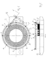
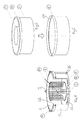
- FIGS 4, 5 and 6 show the apparatus in greater detail.
- Figure 4 shows the circular tank 2 placed inside the outer tank 4.
- An inner limiter 3 is made with poles with braces 27 in between the poles, placed on a reinforced floor or deck 5.
- the poles function as an inner limit for a cargo hold room where the cable shall be placed.
- a bearing 28 for maintaining the inner tank 2 position inside the outer tank 4.
- the upper rim of the inner tank is stiffened with a ring 22.
- the ring 22 is in contact against rollers 9, supported from the outer tank 4.
- Piping 26 for supply or drainage of fluid to the outer tank 4 is shown in the side of the tank.
- One of the pipes may be positioned near the floor of the outer tank 4 for drainage, and the other pipe may be placed in the upper part of the outer tank in order to avoid overfilling.
- Braces 27 are shown on the inner tank 2 floor 5 for stiffening. These may also contribute to keep of the inner tank 2 in steady position when the device shall be transported, and the fluid is drained out.
- the pipes 26 may be a part of a closed circuit with storage tank and a pump for the fluid used.
- the level of filling fluid may be regulated using suitable valves and pumps controlled by units made for the purpose. Parameters for regulating the valves and the pump are for example the position of the inner tank 2, the level of fluid in the interstice between the inner tank 2 and outer tank 4, mass of cable 1 in the inner tank 2.
- a bearing 28 may be placed in the centre of the floor 5 for guidance of the inner tank 2 relative to the outer tank 4.
- the bearing 28 may be a substitute or - or a supplement to the rollers 9.
- Figure 5 shows the inner tank 2 with the upper rim 22 for stiffening and the inner limiter 3.
- Figure 6 shows the outer tank 4 for accommodating the inner tank 2 and fluid.
- the outer tank 4 has an upper part 29 that is widened to make room for the stiffened rim 22 on the inner tank 2.
Landscapes
- Chemical & Material Sciences (AREA)
- Engineering & Computer Science (AREA)
- Combustion & Propulsion (AREA)
- Mechanical Engineering (AREA)
- Ocean & Marine Engineering (AREA)
- Filling Or Discharging Of Gas Storage Vessels (AREA)
- Level Indicators Using A Float (AREA)
- Cooling, Air Intake And Gas Exhaust, And Fuel Tank Arrangements In Propulsion Units (AREA)
Applications Claiming Priority (1)
| Application Number | Priority Date | Filing Date | Title |
|---|---|---|---|
| NO20080488A NO327835B1 (no) | 2008-01-25 | 2008-01-25 | Anordning med en flytende beholder for opptak av kabel |
Publications (3)
| Publication Number | Publication Date |
|---|---|
| EP2085308A2 true EP2085308A2 (de) | 2009-08-05 |
| EP2085308A3 EP2085308A3 (de) | 2010-12-15 |
| EP2085308B1 EP2085308B1 (de) | 2012-04-25 |
Family
ID=40627269
Family Applications (1)
| Application Number | Title | Priority Date | Filing Date |
|---|---|---|---|
| EP20090150849 Not-in-force EP2085308B1 (de) | 2008-01-25 | 2009-01-19 | Vorrichtung mit einem Schwimmbehälter für ein Kabel |
Country Status (3)
| Country | Link |
|---|---|
| EP (1) | EP2085308B1 (de) |
| DK (1) | DK2085308T3 (de) |
| NO (1) | NO327835B1 (de) |
Cited By (7)
| Publication number | Priority date | Publication date | Assignee | Title |
|---|---|---|---|---|
| GB2510048A (en) * | 2012-11-30 | 2014-07-23 | Floating Cable Tanks Ltd | Buoyant conduit storage or deployment system and associated methods |
| WO2015004253A1 (en) * | 2013-07-11 | 2015-01-15 | Maersk Supply Service A/S | A marine vessel |
| GB2533113A (en) * | 2014-12-09 | 2016-06-15 | Magma Global Ltd | Floatable spool apparatus |
| JP2017204935A (ja) * | 2016-05-11 | 2017-11-16 | 一本松物流株式会社 | 船舶のケーブル送り出し装置 |
| WO2018222043A1 (en) * | 2017-06-02 | 2018-12-06 | Ihc Holland Ie B.V. | Carrousel with water bearing |
| WO2019216770A1 (en) | 2018-05-09 | 2019-11-14 | Almek Hydraulic Services As | An apparatus for storing cable |
| NO20180896A1 (en) * | 2018-06-25 | 2019-12-26 | Multi Tech As | Floating cable factory |
Family Cites Families (4)
| Publication number | Priority date | Publication date | Assignee | Title |
|---|---|---|---|---|
| GB1081268A (en) * | 1965-06-18 | 1967-08-31 | Pirelli | Improvements in or relating to floating apparatus for laying or raising submarine cables and the like |
| US3719348A (en) * | 1971-12-15 | 1973-03-06 | Bell Telephone Labor Inc | Cable-handling machine |
| US4647253A (en) * | 1985-10-16 | 1987-03-03 | Jacobson Brothers, Inc. | Cable turntable assembly |
| GB0217511D0 (en) * | 2002-07-30 | 2002-09-04 | Naturalay Ltd | Method and apparatus for laying/recovery of lines on a seabed |
-
2008
- 2008-01-25 NO NO20080488A patent/NO327835B1/no unknown
-
2009
- 2009-01-19 EP EP20090150849 patent/EP2085308B1/de not_active Not-in-force
- 2009-01-19 DK DK09150849T patent/DK2085308T3/da active
Cited By (17)
| Publication number | Priority date | Publication date | Assignee | Title |
|---|---|---|---|---|
| GB2510048A (en) * | 2012-11-30 | 2014-07-23 | Floating Cable Tanks Ltd | Buoyant conduit storage or deployment system and associated methods |
| WO2014083341A3 (en) * | 2012-11-30 | 2015-03-26 | Floating Cable Tanks Limited | Conduit storage or deployment system and associated methods |
| GB2510048B (en) * | 2012-11-30 | 2015-05-27 | Floating Cable Tanks Ltd | Conduit storage or deployment system and associated methods |
| US10035678B2 (en) | 2012-11-30 | 2018-07-31 | Floating Cable Tanks Limited | Conduit storage or deployment system and associated methods |
| WO2015004253A1 (en) * | 2013-07-11 | 2015-01-15 | Maersk Supply Service A/S | A marine vessel |
| DK201370394A1 (en) * | 2013-07-11 | 2015-01-26 | Maersk Supply Service As | A marine vessel |
| GB2533113A (en) * | 2014-12-09 | 2016-06-15 | Magma Global Ltd | Floatable spool apparatus |
| JP2017204935A (ja) * | 2016-05-11 | 2017-11-16 | 一本松物流株式会社 | 船舶のケーブル送り出し装置 |
| WO2018222043A1 (en) * | 2017-06-02 | 2018-12-06 | Ihc Holland Ie B.V. | Carrousel with water bearing |
| NL2019014B1 (en) * | 2017-06-02 | 2018-12-11 | Ihc Holland Ie Bv | Carrousel with water bearing |
| CN110678683A (zh) * | 2017-06-02 | 2020-01-10 | Ihc荷兰Ie有限公司 | 具有水支承的转盘 |
| WO2019216770A1 (en) | 2018-05-09 | 2019-11-14 | Almek Hydraulic Services As | An apparatus for storing cable |
| CN112074453A (zh) * | 2018-05-09 | 2020-12-11 | 阿尔梅克液压服务公司 | 用于存放缆线的设备 |
| US11866286B2 (en) | 2018-05-09 | 2024-01-09 | Almek Hydraulic Services As | Apparatus for storing cable |
| NO20180896A1 (en) * | 2018-06-25 | 2019-12-26 | Multi Tech As | Floating cable factory |
| WO2020005074A1 (en) * | 2018-06-25 | 2020-01-02 | Multi Technology As | Floating cable factory |
| NO344880B1 (en) * | 2018-06-25 | 2020-06-15 | Multi Tech As | Floating cable factory |
Also Published As
| Publication number | Publication date |
|---|---|
| DK2085308T3 (da) | 2012-07-23 |
| NO327835B1 (no) | 2009-10-05 |
| EP2085308B1 (de) | 2012-04-25 |
| EP2085308A3 (de) | 2010-12-15 |
| NO20080488L (no) | 2009-07-27 |
Similar Documents
| Publication | Publication Date | Title |
|---|---|---|
| EP2085308B1 (de) | Vorrichtung mit einem Schwimmbehälter für ein Kabel | |
| RU2570790C2 (ru) | Морская опорная конструкция с устройством для хранения и направления трубопроводов | |
| CN112236614B (zh) | 一种装有装卸塔的密封隔热储罐 | |
| RU2544270C2 (ru) | Устройство для перекачки текучей среды из установленной в море конструкции | |
| US9822767B2 (en) | Floating-body type wind turbine power generating apparatus and method of transporting components of the same | |
| RU2341433C2 (ru) | Хранилище, расположенное на морском дне | |
| CN106061831B (zh) | 用于传输lng和/或电力的传输结构、传输系统和方法 | |
| US5431589A (en) | Submersible mooring buoy | |
| JP5647355B2 (ja) | 可撓性ラインを海に敷設する敷設船および方法 | |
| EP3147200A1 (de) | Installationsschiff für meeresstruktur und verfahren zur installation einer meeresstruktur | |
| KR102511234B1 (ko) | 해상 리프팅 크레인 | |
| WO2002092423A1 (en) | A connector assembly and a connector body for offshore transfer of fluid | |
| WO2000011388A1 (en) | Method and means for storing and/or transporting an elongated tube or cable | |
| RU2440533C2 (ru) | Способ укладки трубопровода в окружности на воде в горизонтальной плоскости | |
| CN104955753A (zh) | 存储或配置管道的系统及相关方法 | |
| JP2017204935A (ja) | 船舶のケーブル送り出し装置 | |
| KR101996810B1 (ko) | 해수공급장치 | |
| KR101665405B1 (ko) | 자연 유하식 적하역 장치 | |
| RU2510453C2 (ru) | Способ отсоединения устройства перекачки текучей среды между дном водного пространства и поверхностью и соответствующее устройство перекачки | |
| GB2533113A (en) | Floatable spool apparatus | |
| WO2004011837A1 (en) | Method and apparatus for laying/recovery of lines on a seabed | |
| KR20160031283A (ko) | 플로트 오버용 터렛 바지선 및 이에 의한 안벽 로드아웃 방법 | |
| NL2012137C2 (en) | Manufacturing of a subsea pipeline and spooling said pipeline onto a reel of a pipelaying vessel at a spoolbase. | |
| EP3790792B1 (de) | Vorrichtung zur aufbewahrung von kabeln | |
| KR200435347Y1 (ko) | 생산저장선박의 공기저항 감소장치 |
Legal Events
| Date | Code | Title | Description |
|---|---|---|---|
| PUAI | Public reference made under article 153(3) epc to a published international application that has entered the european phase |
Free format text: ORIGINAL CODE: 0009012 |
|
| AK | Designated contracting states |
Kind code of ref document: A2 Designated state(s): AT BE BG CH CY CZ DE DK EE ES FI FR GB GR HR HU IE IS IT LI LT LU LV MC MK MT NL NO PL PT RO SE SI SK TR |
|
| AX | Request for extension of the european patent |
Extension state: AL BA RS |
|
| PUAL | Search report despatched |
Free format text: ORIGINAL CODE: 0009013 |
|
| AK | Designated contracting states |
Kind code of ref document: A3 Designated state(s): AT BE BG CH CY CZ DE DK EE ES FI FR GB GR HR HU IE IS IT LI LT LU LV MC MK MT NL NO PL PT RO SE SI SK TR |
|
| AX | Request for extension of the european patent |
Extension state: AL BA RS |
|
| AKX | Designation fees paid |
Designated state(s): DE DK GB SE |
|
| 17P | Request for examination filed |
Effective date: 20090119 |
|
| GRAP | Despatch of communication of intention to grant a patent |
Free format text: ORIGINAL CODE: EPIDOSNIGR1 |
|
| GRAS | Grant fee paid |
Free format text: ORIGINAL CODE: EPIDOSNIGR3 |
|
| GRAA | (expected) grant |
Free format text: ORIGINAL CODE: 0009210 |
|
| AK | Designated contracting states |
Kind code of ref document: B1 Designated state(s): DE DK GB SE |
|
| REG | Reference to a national code |
Ref country code: GB Ref legal event code: FG4D |
|
| REG | Reference to a national code |
Ref country code: SE Ref legal event code: TRGR |
|
| REG | Reference to a national code |
Ref country code: DE Ref legal event code: R096 Ref document number: 602009006482 Country of ref document: DE Effective date: 20120621 |
|
| REG | Reference to a national code |
Ref country code: DK Ref legal event code: T3 |
|
| PLBE | No opposition filed within time limit |
Free format text: ORIGINAL CODE: 0009261 |
|
| STAA | Information on the status of an ep patent application or granted ep patent |
Free format text: STATUS: NO OPPOSITION FILED WITHIN TIME LIMIT |
|
| 26N | No opposition filed |
Effective date: 20130128 |
|
| REG | Reference to a national code |
Ref country code: DE Ref legal event code: R097 Ref document number: 602009006482 Country of ref document: DE Effective date: 20130128 |
|
| PGFP | Annual fee paid to national office [announced via postgrant information from national office to epo] |
Ref country code: DK Payment date: 20230123 Year of fee payment: 15 |
|
| PGFP | Annual fee paid to national office [announced via postgrant information from national office to epo] |
Ref country code: SE Payment date: 20230119 Year of fee payment: 15 Ref country code: GB Payment date: 20230119 Year of fee payment: 15 Ref country code: DE Payment date: 20230123 Year of fee payment: 15 |
|
| REG | Reference to a national code |
Ref country code: DE Ref legal event code: R119 Ref document number: 602009006482 Country of ref document: DE |
|
| REG | Reference to a national code |
Ref country code: DK Ref legal event code: EBP Effective date: 20240131 |
|
| REG | Reference to a national code |
Ref country code: SE Ref legal event code: EUG |
|
| GBPC | Gb: european patent ceased through non-payment of renewal fee |
Effective date: 20240119 |
|
| PG25 | Lapsed in a contracting state [announced via postgrant information from national office to epo] |
Ref country code: DE Free format text: LAPSE BECAUSE OF NON-PAYMENT OF DUE FEES Effective date: 20240801 |
|
| PG25 | Lapsed in a contracting state [announced via postgrant information from national office to epo] |
Ref country code: GB Free format text: LAPSE BECAUSE OF NON-PAYMENT OF DUE FEES Effective date: 20240119 |
|
| PG25 | Lapsed in a contracting state [announced via postgrant information from national office to epo] |
Ref country code: GB Free format text: LAPSE BECAUSE OF NON-PAYMENT OF DUE FEES Effective date: 20240119 Ref country code: DE Free format text: LAPSE BECAUSE OF NON-PAYMENT OF DUE FEES Effective date: 20240801 |
|
| PG25 | Lapsed in a contracting state [announced via postgrant information from national office to epo] |
Ref country code: DK Free format text: LAPSE BECAUSE OF NON-PAYMENT OF DUE FEES Effective date: 20240131 |
|
| PG25 | Lapsed in a contracting state [announced via postgrant information from national office to epo] |
Ref country code: DK Free format text: LAPSE BECAUSE OF NON-PAYMENT OF DUE FEES Effective date: 20240131 |
|
| PG25 | Lapsed in a contracting state [announced via postgrant information from national office to epo] |
Ref country code: SE Free format text: LAPSE BECAUSE OF NON-PAYMENT OF DUE FEES Effective date: 20240120 |